EP1528256A1 - Verdichter mit variabler verdrängung - Google Patents
Verdichter mit variabler verdrängung Download PDFInfo
- Publication number
- EP1528256A1 EP1528256A1 EP03784588A EP03784588A EP1528256A1 EP 1528256 A1 EP1528256 A1 EP 1528256A1 EP 03784588 A EP03784588 A EP 03784588A EP 03784588 A EP03784588 A EP 03784588A EP 1528256 A1 EP1528256 A1 EP 1528256A1
- Authority
- EP
- European Patent Office
- Prior art keywords
- rotor
- plane
- variable displacement
- plate
- swash
- Prior art date
- Legal status (The legal status is an assumption and is not a legal conclusion. Google has not performed a legal analysis and makes no representation as to the accuracy of the status listed.)
- Withdrawn
Links
Images




Classifications
-
- F—MECHANICAL ENGINEERING; LIGHTING; HEATING; WEAPONS; BLASTING
- F04—POSITIVE - DISPLACEMENT MACHINES FOR LIQUIDS; PUMPS FOR LIQUIDS OR ELASTIC FLUIDS
- F04B—POSITIVE-DISPLACEMENT MACHINES FOR LIQUIDS; PUMPS
- F04B27/00—Multi-cylinder pumps specially adapted for elastic fluids and characterised by number or arrangement of cylinders
- F04B27/08—Multi-cylinder pumps specially adapted for elastic fluids and characterised by number or arrangement of cylinders having cylinders coaxial with, or parallel or inclined to, main shaft axis
- F04B27/10—Multi-cylinder pumps specially adapted for elastic fluids and characterised by number or arrangement of cylinders having cylinders coaxial with, or parallel or inclined to, main shaft axis having stationary cylinders
- F04B27/1036—Component parts, details, e.g. sealings, lubrication
- F04B27/1054—Actuating elements
- F04B27/1072—Pivot mechanisms
Definitions
- a piston is contained in each of a plurality of cylinder bores defined in a housing.
- a rotor is provided to a drive shaft that is rotatably supported by the housing. The rotor rotates integrally with the drive shaft.
- a cam plate (swash plate) is supported slidably and tiltably by the drive shaft.
- a hinge mechanism is provided between the rotor and the cam plate. The rotary motion of the drive shaft is converted into the reciprocating motion of the pistons through the rotor, the hinge mechanism, and the cam plate. Accordingly, the compression of a refrigerant gas is performed.
- the hinge mechanism guides the cam plate so that the cam plate slides on the drive shaft while tilting. According to an inclination angle of the cam plate, the stroke of the pistons, that is, the displacement of the variable displacement compressor is changed.
- Cylinder bores 22 are formed in the above-mentioned cylinder block 11.
- the cylinder bores 22 are arranged at equal angular intervals around the axis L of the drive shaft 16.
- the cylinder bores 22 are extended along with the axis L of the drive shaft 16.
- a single-headed piston 23 is accommodated in each of the cylinder bores 22.
- Each piston 22 reciprocates in the corresponding cylinder bore 22.
- Front and back openings of each of the cylinder bores 22 are blocked by a front end face 13a of a valve and port assembly 13 and a corresponding one of the pistons 23, respectively, and a compression chamber 24, the volume of which changes according to the reciprocating motion of the corresponding one of the pistons 23, is provided in that one of the cylinder bores 22.
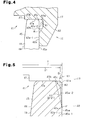
- Cylinder faces 45b and 46b which are convex surfaces, are formed at ends of the above-mentioned swash-plate-side protrusions 45 and 46, respectively.
- the main axis S of the respective cylindrical faces 45b and 46b is perpendicular to the side faces 45a and 46a.
- the ends of the respective swash-plate-side protrusions 45 and 46 slidably abut against the cam face 47a of the corresponding cam portion 47 through the cylindrical faces 45b and 46b. Therefore, the axial load that acts on the swash plate 18 because of compression reaction force etc. is received by the cam face 47a of the cam portion 47 through the cylindrical faces 45b and 46b of the swash-plate-side protrusions 45 and 46.
- a protruding portion 73 is provided in a position corresponding to the engaging groove 70.
- the protruding portion 73 transmits power to a side face 71a of the wall portion 71 in the swash plate 18 with a side face 73a in the state of being inserted and engaged between the side faces (wall surfaces) 71a and 72a of the wall portions 71 and 72, which face each other (when the rotational direction of the drive shaft 16 is the direction shown by the arrow R).
- the protruding portion 73 transmits power to the side face 72a of the wall portion 72 in the swash plate 18 with a side face 73b.
Landscapes
- Engineering & Computer Science (AREA)
- Mechanical Engineering (AREA)
- General Engineering & Computer Science (AREA)
- Compressors, Vaccum Pumps And Other Relevant Systems (AREA)
Applications Claiming Priority (3)
| Application Number | Priority Date | Filing Date | Title |
|---|---|---|---|
| JP2002230216 | 2002-08-07 | ||
| JP2002230216 | 2002-08-07 | ||
| PCT/JP2003/010094 WO2004015269A1 (ja) | 2002-08-07 | 2003-08-07 | 容量可変型圧縮機 |
Publications (1)
| Publication Number | Publication Date |
|---|---|
| EP1528256A1 true EP1528256A1 (de) | 2005-05-04 |
Family
ID=31711674
Family Applications (1)
| Application Number | Title | Priority Date | Filing Date |
|---|---|---|---|
| EP03784588A Withdrawn EP1528256A1 (de) | 2002-08-07 | 2003-08-07 | Verdichter mit variabler verdrängung |
Country Status (4)
| Country | Link |
|---|---|
| US (1) | US20050147503A1 (de) |
| EP (1) | EP1528256A1 (de) |
| JP (1) | JPWO2004015269A1 (de) |
| WO (1) | WO2004015269A1 (de) |
Families Citing this family (5)
| Publication number | Priority date | Publication date | Assignee | Title |
|---|---|---|---|---|
| JP4626808B2 (ja) * | 2005-04-26 | 2011-02-09 | 株式会社豊田自動織機 | 可変容量型クラッチレス圧縮機用の容量制御弁 |
| US7455009B2 (en) * | 2006-06-09 | 2008-11-25 | Visteon Global Technologies, Inc. | Hinge for a variable displacement compressor |
| US8118567B2 (en) * | 2006-12-15 | 2012-02-21 | Kabushiki Kaisha Kawasaki Precision Machinery | Swash plate type piston pump motor |
| KR101907696B1 (ko) * | 2012-06-22 | 2018-10-15 | 학교법인 두원학원 | 용량가변형 사판식 압축기 |
| US10309382B2 (en) * | 2014-06-27 | 2019-06-04 | Valeo Japan Co., Ltd. | Variable displacement swash plate compressor |
Family Cites Families (7)
| Publication number | Priority date | Publication date | Assignee | Title |
|---|---|---|---|---|
| JP2846089B2 (ja) * | 1990-09-14 | 1999-01-13 | 株式会社日立製作所 | 可変容量形圧縮機 |
| JPH05312144A (ja) * | 1992-05-08 | 1993-11-22 | Sanden Corp | 可変容量斜板式圧縮機 |
| JPH0814159A (ja) * | 1994-06-27 | 1996-01-16 | Sanden Corp | 斜板式可変容量圧縮機 |
| JP3422186B2 (ja) * | 1995-11-24 | 2003-06-30 | 株式会社豊田自動織機 | 可変容量圧縮機 |
| JP2000145653A (ja) * | 1998-11-12 | 2000-05-26 | Toyota Autom Loom Works Ltd | 可変容量型圧縮機 |
| JP2001304102A (ja) * | 2000-04-18 | 2001-10-31 | Toyota Industries Corp | 可変容量圧縮機 |
| JPWO2005024233A1 (ja) * | 2003-09-02 | 2006-11-02 | 株式会社豊田自動織機 | 容量可変型斜板式圧縮機 |
-
2003
- 2003-08-07 US US10/510,387 patent/US20050147503A1/en not_active Abandoned
- 2003-08-07 WO PCT/JP2003/010094 patent/WO2004015269A1/ja not_active Ceased
- 2003-08-07 JP JP2004527365A patent/JPWO2004015269A1/ja active Pending
- 2003-08-07 EP EP03784588A patent/EP1528256A1/de not_active Withdrawn
Non-Patent Citations (1)
| Title |
|---|
| See references of WO2004015269A1 * |
Also Published As
| Publication number | Publication date |
|---|---|
| US20050147503A1 (en) | 2005-07-07 |
| JPWO2004015269A1 (ja) | 2005-12-02 |
| WO2004015269A1 (ja) | 2004-02-19 |
Similar Documents
| Publication | Publication Date | Title |
|---|---|---|
| EP1394411B1 (de) | Taumelscheibenkompressor mit variabler Verdrängung | |
| US6629823B2 (en) | Compressors | |
| EP1528256A1 (de) | Verdichter mit variabler verdrängung | |
| US20050058551A1 (en) | Swash plate type variable displacement compressor | |
| US20030131725A1 (en) | Variable displacement compressor | |
| KR100529716B1 (ko) | 경사이동이 원활한 용량 가변형 사판식 압축기 | |
| US20040055456A1 (en) | Variable displacement compressor | |
| KR101175272B1 (ko) | 용량 가변형 사판식 압축기 | |
| EP1092872B1 (de) | Kolben für Taumelscheibenverdichter | |
| WO2008066224A1 (en) | Variable displacement swash plate type compressor | |
| KR101806189B1 (ko) | 용량 가변형 사판식 압축기 | |
| KR101769424B1 (ko) | 용량 가변형 사판식 압축기 | |
| US20090214360A1 (en) | Tilting plate type compressor | |
| JPH08109874A (ja) | 斜板式コンプレッサ | |
| JP2755193B2 (ja) | 圧縮機におけるピストン | |
| JP3937690B2 (ja) | 圧縮機 | |
| EP1531266B1 (de) | Kompressor mit veränderlicher Verdrängung | |
| JP2000120533A (ja) | 容量可変型斜板式圧縮機 | |
| JP3320587B2 (ja) | 斜板式コンプレッサ | |
| EP1548282B1 (de) | Taumelscheibenverdichter | |
| KR100792501B1 (ko) | 사판식 압축기에서의 구동축과 사판의 연결구조 | |
| KR101631211B1 (ko) | 용량 가변형 사판식 압축기 | |
| KR100519745B1 (ko) | 용량가변형 사판식 압축기 | |
| US20060222513A1 (en) | Swash plate type variable displacement compressor | |
| JPH0960584A (ja) | 可変容量圧縮機 |
Legal Events
| Date | Code | Title | Description |
|---|---|---|---|
| PUAI | Public reference made under article 153(3) epc to a published international application that has entered the european phase |
Free format text: ORIGINAL CODE: 0009012 |
|
| 17P | Request for examination filed |
Effective date: 20041007 |
|
| AK | Designated contracting states |
Kind code of ref document: A1 Designated state(s): AT BE BG CH CY CZ DE DK EE ES FI FR GB GR HU IE IT LI LU MC NL PT RO SE SI SK TR |
|
| STAA | Information on the status of an ep patent application or granted ep patent |
Free format text: STATUS: THE APPLICATION HAS BEEN WITHDRAWN |
|
| 18W | Application withdrawn |
Effective date: 20050425 |