EP1548282B1 - Taumelscheibenverdichter - Google Patents
Taumelscheibenverdichter Download PDFInfo
- Publication number
- EP1548282B1 EP1548282B1 EP04030623A EP04030623A EP1548282B1 EP 1548282 B1 EP1548282 B1 EP 1548282B1 EP 04030623 A EP04030623 A EP 04030623A EP 04030623 A EP04030623 A EP 04030623A EP 1548282 B1 EP1548282 B1 EP 1548282B1
- Authority
- EP
- European Patent Office
- Prior art keywords
- swash plate
- support surface
- plate support
- slide plate
- slide
- Prior art date
- Legal status (The legal status is an assumption and is not a legal conclusion. Google has not performed a legal analysis and makes no representation as to the accuracy of the status listed.)
- Expired - Lifetime
Links
- 239000003507 refrigerant Substances 0.000 claims description 23
- CURLTUGMZLYLDI-UHFFFAOYSA-N Carbon dioxide Chemical compound O=C=O CURLTUGMZLYLDI-UHFFFAOYSA-N 0.000 claims description 10
- 229910002092 carbon dioxide Inorganic materials 0.000 claims description 5
- 239000001569 carbon dioxide Substances 0.000 claims description 5
- 230000003247 decreasing effect Effects 0.000 claims 1
- 230000006835 compression Effects 0.000 description 28
- 238000007906 compression Methods 0.000 description 28
- 238000006243 chemical reaction Methods 0.000 description 20
- 230000002093 peripheral effect Effects 0.000 description 12
- 238000006073 displacement reaction Methods 0.000 description 8
- 238000010586 diagram Methods 0.000 description 5
- 238000005299 abrasion Methods 0.000 description 3
- 238000003780 insertion Methods 0.000 description 3
- 230000037431 insertion Effects 0.000 description 3
- 239000000314 lubricant Substances 0.000 description 3
- 239000010726 refrigerant oil Substances 0.000 description 3
- 230000000694 effects Effects 0.000 description 2
- 230000000717 retained effect Effects 0.000 description 2
- 238000009499 grossing Methods 0.000 description 1
- 238000005461 lubrication Methods 0.000 description 1
- 239000000463 material Substances 0.000 description 1
- 238000005096 rolling process Methods 0.000 description 1
Images


Classifications
-
- F—MECHANICAL ENGINEERING; LIGHTING; HEATING; WEAPONS; BLASTING
- F04—POSITIVE - DISPLACEMENT MACHINES FOR LIQUIDS; PUMPS FOR LIQUIDS OR ELASTIC FLUIDS
- F04B—POSITIVE-DISPLACEMENT MACHINES FOR LIQUIDS; PUMPS
- F04B27/00—Multi-cylinder pumps specially adapted for elastic fluids and characterised by number or arrangement of cylinders
- F04B27/08—Multi-cylinder pumps specially adapted for elastic fluids and characterised by number or arrangement of cylinders having cylinders coaxial with, or parallel or inclined to, main shaft axis
- F04B27/10—Multi-cylinder pumps specially adapted for elastic fluids and characterised by number or arrangement of cylinders having cylinders coaxial with, or parallel or inclined to, main shaft axis having stationary cylinders
- F04B27/1036—Component parts, details, e.g. sealings, lubrication
- F04B27/1054—Actuating elements
- F04B27/1063—Actuating-element bearing means or driving-axis bearing means
Definitions
- the present invention relates to a swash plate compressor for compressing refrigerant gas in, for example, a refrigerant circuit for a vehicle air conditioner.
- a typical swash plate compressor includes a drive shaft and a swash plate connected to the drive shaft so as to rotate integrally with the drive shaft.
- Single headed pistons are connected to the peripheral portion of the swash plate by pairs of shoes. As the swash plate rotates when the drive shaft rotates, the swash plate rotates between the shoes as it wobbles with respect to the axial direction of the drive shaft. This reciprocates each piston to compress refrigerant gas.
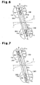
- a thrust bearing 53 (roller bearing) is arranged between the swash plate 18 and the rear shoes 30B (the shoes 30B that receive compression reaction from the pistons 28), that is, between the shoes 30A and 30B.
- the thrust bearing 53 is arranged between the peripheral rear surface of the swash plate 18 and the peripheral front surface of the slide plate 51.
- the thrust bearing 53 includes a plurality of rollers 53a. The rollers 53a are arranged along the circumferential direction of the swash plate 18.
- An annular slide plate support surface 51b is defined on the peripheral front surface of the slide plate 51.
- the slide plate support surface 51b receives the thrust bearing 53.
- the rollers 53a of the thrust bearing 53 are arranged on the slide plate support surface 51b in a rollable manner.
- the slide plate support surface 51b functions as a roll surface for the rollers 53a.
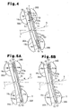
- Fig. 4 is a schematic diagram showing the vicinity of the peripheral portion of the swash plate 18. As shown in Fig. 4, a clearance CL is provided between the swash plate support surface 18b and the slide plate support surface 51b. In comparison to the radially outer side of the swash plate 18, the clearance CL is larger at the radially inner side of the swash plate 18.
- the difference between the clearance CL at where it is largest (indicated by CL1 in Fig. 4) and the clearance CL at where it is smallest (indicated by CL2 in Fig. 4) is about several tens of micrometers.
- the difference between the clearance CL at the inner side of the swash plate 18 and the clearance CL at the outer side of the swash plate 18, that is, the inclination of the swash plate support surface 18b relative to the slide plate support surface 51b is shown in an exaggerated manner.
- compression reaction (the load center of which is indicated by arrow X to facilitate understanding) is applied to the rear surface of the swash plate 18 from the piston 28 that is in the compression stroke via the associated shoe 30B, the slide plate 51, and the thrust bearing 53. More specifically, compression reaction X is applied in an eccentric manner to the rear surface of the swash plate 18 about the axis L of the drive shaft 16.
- the compression reaction X is relatively large when the displacement of the compressor 10 is relatively large. This flexes the peripheral portion of the swash plate 18 at parts to which the compression reaction X is applied (refer to lower part of Fig. 5A).
- the preferred embodiment when the hypothetical plane H is located between the swash plate support surface 18b and the slide plate support surface 51b, the preferred embodiment may be modified so that the slide plate support surface 51b is inclined relative to the hypothetic plane H and gradually spaced from the hypothetical plane H radially inwardly of the slide plate 51.
- the swash plate support surface 18b may be parallel to the hypothetical plane H while the slide plate support surface 51b is inclined relative to the hypothetical plane H and gradually spaced from the swash plate support surface 18b radially inwardly of the slide plate 51.
- a swash plate compressor that prevents a slide plate from being separated from a swash plate.
- the compressor (10) includes a drive shaft (16).
- a slide plate (51) is rotatable relative to the swash plate (18).
- Two shoes (30A, 30B) is arranged on the swash plate and the slide plate.
- a bearing (53) arranged between the swash plate and the slide plate and in between the shoes.
- a piston (28) is connected to the swash plate and the slide plate by the shoes and is reciprocated to compress gas.
- the swash plate includes a swash plate support surface (18b), and the slide plate includes a slide plate support surface (51b), in which each surface is for contacting the bearing.
- the swash plate is formed so that a clearance (CL) between the swash plate support surface and the slide plate support surface increases radially inwardly of the swash plate and the slide plate.
Landscapes
- Engineering & Computer Science (AREA)
- Mechanical Engineering (AREA)
- General Engineering & Computer Science (AREA)
- Compressors, Vaccum Pumps And Other Relevant Systems (AREA)
- Compressor (AREA)
Claims (10)
- Ein Taumelscheibenverdichter (10) zum Verdichten eines Gases, wobei der Verdichter eine drehbaren Antriebswelle (16), einer Taumelscheibe (18), die mit der Antriebswelle derart verbunden ist, dass eine einstückige Drehung mit der Antriebswelle möglich ist, eine Gleitplatte (51), die bezüglich der Taumelscheibe drehbar gelagert ist, ein Paar Gleitschuhe (30A, 30B), die auf der Taumelscheibe und der Gleitplatte angeordnet sind, ein Lager (53), das zwischen der Taumelscheibe und der Gleitplatte und zwischen den Gleitschuhen angeordnet ist, und einen Kolben (28) hat, der mit der Taumelscheibe und der Gleitplatte durch die Gleitschuhe verbunden ist und hin- und herbewegt wird, um Gas zu verdichten, wenn die Drehung der Antriebswelle die Taumelscheibe dreht, wobei die Taumelscheibe eine Taumelscheibenstützfläche (18b) zur Anlage an dem Lager hat, und wobei die Gleitplatte eine Gleitplattenstützfläche (51b) zur Anlage an dem Lager hat, wobei der Verdichter dadurch gekennzeichnet ist, dass
mindestens eine von der Taumelscheibe und der Gleitplatte so geformt ist, dass ein Abstand (CL) zwischen der Taumelscheibenstützfläche und der Gleitplattenstützfläche radial einwärts der Taumelscheibe und der Gleitplatte zunimmt. - Der Verdichter gemäß Anspruch 1 ist dadurch gekennzeichnet, dass mindestens eine von der Taumelscheibenstützfläche und der Gleitplattenstützfläche relativ zu einer zur Achse (S) der Taumelscheibe senkrechten, hypothetischen Ebene geneigt ist, so dass der Raum zwischen den Flächen radial einwärts der Taumelscheibe und der Gleitplatte allmählich zunimmt, und der Abstand zwischen der Taumelscheibenstützfläche und der Gleitplattenstützfläche radial einwärts von der Taumelscheibe und der Gleitplatte allmählich zunimmt.
- Der Verdichter gemäß Anspruch 1 oder 2 ist dadurch gekennzeichnet, dass das Lager eine rollende Walze (53a) enthält, und die Taumelscheibenstützfläche und die Gleitplattenstützfläche jeweils eine Wälzfläche begrenzen, auf der die Walze rollt.
- Der Verdichter gemäß einem der Ansprüche 1 bis 3 ist dadurch gekennzeichnet, dass die Gleitplatte flexibel ist.
- Der Verdichter gemäß Anspruch 1 ist dadurch gekennzeichnet, dass der Taumelscheibenverdichter einen Teil eines Kältemittelkreislaufs (70) darstellt und Kohlendioxid-Kühlgas verdichtet.
- Der Verdichter gemäß Anspruch 1 ist dadurch gekennzeichnet, dass eine von der Taumelscheibenstützfläche und der Gleitplattenstützfläche parallel zu einer zur Achse (S) der Taumelscheibe senkrechten, hypothetischen Ebene ist, und die andere von der Taumelscheibenstützfläche und der Gleitplattenstützfläche relativ zu der hypothetischen Ebene geneigt ist, wobei der Raum der Flächen radial einwärts von der Taumelscheibe und der Gleitplatte allmählich zunimmt.
- Der Verdichter gemäß Anspruch 1 ist dadurch gekennzeichnet, dass, wenn eine sich senkrecht zur Achse der Taumelscheibe erstreckende, hypothetische Ebene zwischen der Taumelscheibenstützfläche und der Gleitplattenstützfläche definiert ist, die Taumelscheibenstützfläche und die Gleitplattenstützfläche relativ zu der hypothetischen Ebene geneigt sind, wobei der Raum der Flächen zu der hypothetischen Ebene radial einwärts der Taumelscheibe und der Gleitplatte allmählich zunimmt .
- Der Verdichter gemäß Anspruch 1 ist dadurch gekennzeichnet, dass, wenn eine sich senkrecht zur Achse der Taumelscheibe erstreckende, hypothetische Ebene zwischen der Taumelscheibenstützfläche und der Gleitplattenstützfläche definiert ist:eine von der Taumelscheibenstützfläche und der Gleitplattenstützfläche relativ zur hypothetischen Ebene geneigt ist, wobei der Raum der Flächen zu der hypothetischen Ebene radial einwärts der Taumelscheibenstützfläche und der Gleitplattenstützfläche allmählich zunimmt;die andere von der Taumelscheibenstützfläche und der Gleitplattenstützfläche relativ zur hypothetischen Ebene geneigt ist, wobei der Raum der anderen von den Flächen zu der hypothetischen Ebene radial einwärts der Taumelscheibenstützfläche und der Gleitplattenstützfläche allmählich abnimmt; undein Winkel zwischen der hypothetischen Ebene und der anderen von der Taumelscheibenstützfläche und der Gleitplattenstützfläche kleiner ist als ein Winkel zwischen der hypothetischen Ebene und der einen von der Taumelscheibenstützfläche und der Gleitplattenstützfläche.
- Der Verdichter gemäß Anspruch 1 ist dadurch gekennzeichnet, dass eine von der Taumelscheibenstützfläche und der Gleitplattenstützfläche durch einen Teil einer kegelförmigen Fläche gebildet ist.
- Der Verdichter gemäß Anspruch 1 ist dadurch gekennzeichnet, dass der Abstand zwischen der Taumelscheibenstützfläche und der Gleitplattenstützfläche einen maximalen Wert und einen minimalen Wert hat, wobei die Differenz 30 Mikrometer oder größer ist.
Applications Claiming Priority (2)
| Application Number | Priority Date | Filing Date | Title |
|---|---|---|---|
| JP2003431617 | 2003-12-25 | ||
| JP2003431617A JP2005188406A (ja) | 2003-12-25 | 2003-12-25 | 斜板式圧縮機 |
Publications (3)
| Publication Number | Publication Date |
|---|---|
| EP1548282A2 EP1548282A2 (de) | 2005-06-29 |
| EP1548282A3 EP1548282A3 (de) | 2006-02-01 |
| EP1548282B1 true EP1548282B1 (de) | 2007-02-14 |
Family
ID=34545053
Family Applications (1)
| Application Number | Title | Priority Date | Filing Date |
|---|---|---|---|
| EP04030623A Expired - Lifetime EP1548282B1 (de) | 2003-12-25 | 2004-12-23 | Taumelscheibenverdichter |
Country Status (4)
| Country | Link |
|---|---|
| US (1) | US7168359B2 (de) |
| EP (1) | EP1548282B1 (de) |
| JP (1) | JP2005188406A (de) |
| DE (1) | DE602004004740T2 (de) |
Families Citing this family (2)
| Publication number | Priority date | Publication date | Assignee | Title |
|---|---|---|---|---|
| US20070081904A1 (en) * | 2003-09-02 | 2007-04-12 | Hajime Kurita | Variable displacement type compressor |
| JP4626808B2 (ja) * | 2005-04-26 | 2011-02-09 | 株式会社豊田自動織機 | 可変容量型クラッチレス圧縮機用の容量制御弁 |
Family Cites Families (4)
| Publication number | Priority date | Publication date | Assignee | Title |
|---|---|---|---|---|
| US1714145A (en) * | 1922-11-14 | 1929-05-21 | Sperry Dev Co | Crankless engine |
| JPS60219479A (ja) | 1984-04-16 | 1985-11-02 | Toyoda Autom Loom Works Ltd | 斜板式コンプレツサ |
| JPS61149588A (ja) | 1984-12-24 | 1986-07-08 | Taiho Kogyo Co Ltd | 斜板式コンプレツサ |
| JP2001032768A (ja) | 1999-07-19 | 2001-02-06 | Zexel Valeo Climate Control Corp | 可変容量型斜板式圧縮機 |
-
2003
- 2003-12-25 JP JP2003431617A patent/JP2005188406A/ja active Pending
-
2004
- 2004-12-22 US US11/020,452 patent/US7168359B2/en not_active Expired - Fee Related
- 2004-12-23 DE DE602004004740T patent/DE602004004740T2/de not_active Expired - Fee Related
- 2004-12-23 EP EP04030623A patent/EP1548282B1/de not_active Expired - Lifetime
Also Published As
| Publication number | Publication date |
|---|---|
| US20050145105A1 (en) | 2005-07-07 |
| US7168359B2 (en) | 2007-01-30 |
| DE602004004740D1 (de) | 2007-03-29 |
| EP1548282A3 (de) | 2006-02-01 |
| DE602004004740T2 (de) | 2007-10-31 |
| EP1548282A2 (de) | 2005-06-29 |
| JP2005188406A (ja) | 2005-07-14 |
Similar Documents
| Publication | Publication Date | Title |
|---|---|---|
| US4712982A (en) | Variable displacement wobble plate type compressor with guide means for wobble plate | |
| KR100274497B1 (ko) | 압축기 | |
| EP1394411B1 (de) | Taumelscheibenkompressor mit variabler Verdrängung | |
| JP2006022785A (ja) | 容量可変型圧縮機 | |
| US20020025259A1 (en) | Compressor | |
| US6010313A (en) | Single-headed piston type compressor | |
| US6629823B2 (en) | Compressors | |
| EP2574786B1 (de) | Verdichter | |
| JP3790942B2 (ja) | 斜板式圧縮機 | |
| EP1548282B1 (de) | Taumelscheibenverdichter | |
| US6393964B1 (en) | Compressor having piston rotation restricting structure with lubricating inclined guide surface | |
| US20050158182A1 (en) | Piston type compressor | |
| KR20030042416A (ko) | 사판형 압축기 | |
| JP2755193B2 (ja) | 圧縮機におけるピストン | |
| KR100679909B1 (ko) | 사판식 압축기 | |
| KR101181157B1 (ko) | 가변 용량형 압축기의 구동축 지지구조 | |
| JPH10213062A (ja) | 可変容量型斜板式圧縮機 | |
| US20070101859A1 (en) | Compressor | |
| WO2005024233A1 (ja) | 容量可変型斜板式圧縮機 | |
| JP2000120533A (ja) | 容量可変型斜板式圧縮機 | |
| EP0911521B1 (de) | Schmierfluidkanäle in der rotierenden Antriebsplatte eines Taumelscheibenkompressors | |
| KR20060085002A (ko) | 피스톤의 자전방지구조, 및 이를 포함하는 용량 가변형사판식 압축기 | |
| EP1531266A2 (de) | Kompressor mit veränderlicher Verdrängung | |
| JP2001165046A (ja) | 圧縮機 | |
| KR101142767B1 (ko) | 압축기용 피스톤 |
Legal Events
| Date | Code | Title | Description |
|---|---|---|---|
| PUAI | Public reference made under article 153(3) epc to a published international application that has entered the european phase |
Free format text: ORIGINAL CODE: 0009012 |
|
| 17P | Request for examination filed |
Effective date: 20041223 |
|
| AK | Designated contracting states |
Kind code of ref document: A2 Designated state(s): AT BE BG CH CY CZ DE DK EE ES FI FR GB GR HU IE IS IT LI LT LU MC NL PL PT RO SE SI SK TR |
|
| AX | Request for extension of the european patent |
Extension state: AL BA HR LV MK YU |
|
| PUAL | Search report despatched |
Free format text: ORIGINAL CODE: 0009013 |
|
| AK | Designated contracting states |
Kind code of ref document: A3 Designated state(s): AT BE BG CH CY CZ DE DK EE ES FI FR GB GR HU IE IS IT LI LT LU MC NL PL PT RO SE SI SK TR |
|
| AX | Request for extension of the european patent |
Extension state: AL BA HR LV MK YU |
|
| GRAP | Despatch of communication of intention to grant a patent |
Free format text: ORIGINAL CODE: EPIDOSNIGR1 |
|
| GRAS | Grant fee paid |
Free format text: ORIGINAL CODE: EPIDOSNIGR3 |
|
| AKX | Designation fees paid |
Designated state(s): DE FR IT |
|
| GRAA | (expected) grant |
Free format text: ORIGINAL CODE: 0009210 |
|
| AK | Designated contracting states |
Kind code of ref document: B1 Designated state(s): DE FR IT |
|
| REF | Corresponds to: |
Ref document number: 602004004740 Country of ref document: DE Date of ref document: 20070329 Kind code of ref document: P |
|
| ET | Fr: translation filed | ||
| PLBE | No opposition filed within time limit |
Free format text: ORIGINAL CODE: 0009261 |
|
| STAA | Information on the status of an ep patent application or granted ep patent |
Free format text: STATUS: NO OPPOSITION FILED WITHIN TIME LIMIT |
|
| 26N | No opposition filed |
Effective date: 20071115 |
|
| PGFP | Annual fee paid to national office [announced via postgrant information from national office to epo] |
Ref country code: IT Payment date: 20081223 Year of fee payment: 5 |
|
| PGFP | Annual fee paid to national office [announced via postgrant information from national office to epo] |
Ref country code: FR Payment date: 20081216 Year of fee payment: 5 |
|
| PGFP | Annual fee paid to national office [announced via postgrant information from national office to epo] |
Ref country code: DE Payment date: 20081230 Year of fee payment: 5 |
|
| REG | Reference to a national code |
Ref country code: FR Ref legal event code: ST Effective date: 20100831 |
|
| PG25 | Lapsed in a contracting state [announced via postgrant information from national office to epo] |
Ref country code: FR Free format text: LAPSE BECAUSE OF NON-PAYMENT OF DUE FEES Effective date: 20091231 |
|
| PG25 | Lapsed in a contracting state [announced via postgrant information from national office to epo] |
Ref country code: DE Free format text: LAPSE BECAUSE OF NON-PAYMENT OF DUE FEES Effective date: 20100701 |
|
| PG25 | Lapsed in a contracting state [announced via postgrant information from national office to epo] |
Ref country code: IT Free format text: LAPSE BECAUSE OF NON-PAYMENT OF DUE FEES Effective date: 20091223 |