EP1528245A1 - Kolben für einen Verbrennungsmotor - Google Patents
Kolben für einen Verbrennungsmotor Download PDFInfo
- Publication number
- EP1528245A1 EP1528245A1 EP04025799A EP04025799A EP1528245A1 EP 1528245 A1 EP1528245 A1 EP 1528245A1 EP 04025799 A EP04025799 A EP 04025799A EP 04025799 A EP04025799 A EP 04025799A EP 1528245 A1 EP1528245 A1 EP 1528245A1
- Authority
- EP
- European Patent Office
- Prior art keywords
- piston
- crown
- ribs
- thrust side
- thrust
- Prior art date
- Legal status (The legal status is an assumption and is not a legal conclusion. Google has not performed a legal analysis and makes no representation as to the accuracy of the status listed.)
- Granted
Links
- 238000002485 combustion reaction Methods 0.000 title claims abstract description 31
- 239000000567 combustion gas Substances 0.000 description 11
- 238000004880 explosion Methods 0.000 description 5
- 239000000446 fuel Substances 0.000 description 5
- 239000000203 mixture Substances 0.000 description 5
- 238000005266 casting Methods 0.000 description 2
- 238000006243 chemical reaction Methods 0.000 description 2
- 230000008878 coupling Effects 0.000 description 2
- 238000010168 coupling process Methods 0.000 description 2
- 238000005859 coupling reaction Methods 0.000 description 2
- 230000008034 disappearance Effects 0.000 description 2
- 239000000314 lubricant Substances 0.000 description 2
- 239000000463 material Substances 0.000 description 2
- 230000002093 peripheral effect Effects 0.000 description 2
- 229910000838 Al alloy Inorganic materials 0.000 description 1
- VYZAMTAEIAYCRO-UHFFFAOYSA-N Chromium Chemical compound [Cr] VYZAMTAEIAYCRO-UHFFFAOYSA-N 0.000 description 1
- 229910000831 Steel Inorganic materials 0.000 description 1
- 229910001069 Ti alloy Inorganic materials 0.000 description 1
- 229910052804 chromium Inorganic materials 0.000 description 1
- 239000011651 chromium Substances 0.000 description 1
- VNTLIPZTSJSULJ-UHFFFAOYSA-N chromium molybdenum Chemical compound [Cr].[Mo] VNTLIPZTSJSULJ-UHFFFAOYSA-N 0.000 description 1
- 238000001816 cooling Methods 0.000 description 1
- 230000000694 effects Effects 0.000 description 1
- 230000017525 heat dissipation Effects 0.000 description 1
- 238000010438 heat treatment Methods 0.000 description 1
- 230000013011 mating Effects 0.000 description 1
- 239000010959 steel Substances 0.000 description 1
Images


Classifications
-
- F—MECHANICAL ENGINEERING; LIGHTING; HEATING; WEAPONS; BLASTING
- F16—ENGINEERING ELEMENTS AND UNITS; GENERAL MEASURES FOR PRODUCING AND MAINTAINING EFFECTIVE FUNCTIONING OF MACHINES OR INSTALLATIONS; THERMAL INSULATION IN GENERAL
- F16J—PISTONS; CYLINDERS; SEALINGS
- F16J1/00—Pistons; Trunk pistons; Plungers
- F16J1/10—Connection to driving members
- F16J1/14—Connection to driving members with connecting-rods, i.e. pivotal connections
- F16J1/22—Connection to driving members with connecting-rods, i.e. pivotal connections with universal joint, e.g. ball-joint
Definitions
- This invention relates to a piston for an internal combustion engine, which is coupled to a small end of a connecting rod via a spherical joint.
- a piston for an internal combustion engine which is coupled to a connecting rod by a spherical joint is known from, for example, JP-A-9-144879 and JP-A-2000-213646.
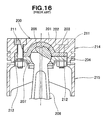
- JP-A-9-144879 will be explained with reference to FIG. 16 hereof and JP-A- 2000-213646 with reference to FIG. 17 hereof.
- a piston 200 has a concave spherical washer 203 having a concave spherical surface 202 and held on the rear surface of a crown 201 with a retainer 204, a connecting rod 206 having a convex spherical surface 208 formed on a small end 207 thereof and fitted slidably in the concave spherical surface 202 of the washer.
- the concave spherical washer 203 and the retainer 204 on the rear surface of the crown 201 add to the weight of the piston 200. A reduction of its weight is difficult, since the concave spherical washer 203, retainer 204, bolts 211 and nuts 212 occupy the space under the crown 201 and do not allow the thickness of the crown 201 to be reduced.
- the concave spherical washer 203 is made of an iron- based material while the piston 200 is of an aluminum alloy, the concave spherical washer 203 is so low in thermal conductivity that heat is not conducted from the crown 201 to, for example, the connecting rod 206 easily. Accordingly, the crown 201 has a high temperature, raising the temperature of a land 214 and a skirt 215 near ring grooves adjacent to the crown 201 and thereby increasing the thermal expansion of the land 214 and the skirt 215. This makes it impossible to secure a proper clearance between the piston 200 and the wall of a cylinder bore in which the piston 200 is slidable.
- a piston 220 has a spherical recess 221 formed in the rear surface of its crown 220a, while a connecting rod 222 has a spherical top 223 fitted in the spherical recess 221 and having a lower portion supported slidably on the spherical inner surface 226 of a fixing plate 224 secured to the rear surface of the crown 220a of the piston 220 by bolts 227.
- the crown 220a of the piston 220 has a large thickness, since its rear surface is situated at as low a level as the vertically middle portion of the top 223 of the connecting rod 222 so that the fixing plate 224 may be secured thereto.
- a reduction in thickness of the crown 220a would enable a reduction in weight of the piston. It would, however, be necessary to prevent the concentration of stress on the crown 220a from being caused by the pressure of combustion gases and force of inertia acting upon the piston 220.
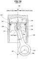
- a piston 232 is movably mounted in a cylinder 231 and a connecting rod 234 has a small end 236 attached to the piston 232 rotatably by a piston pin 233.
- the connecting rod 234 also has a big end 237 linked to a crank pin on a crankshaft.
- Reference numerals 241, 242 and 243 denote the crown, land and skirt, respectively, of the piston 232, 244 denotes a combustion chamber, 246 is a point indicating the axis of the crank pin, 247 is a point indicating the axis of the crankshaft and 248 indicates the axis of the cylinder 231.
- That side of the piston 232 on which the thrust R is produced is called the thrust side, which lies in FIG. 18 on the left-hand side of a plane extending through the axis of rotation of the connecting rod 234 relative to the piston 232 (i.e. the axis of the piston pin 233 extending at right angles to the drawing sheet and indicated by a point 250) and in parallel to the axis 248, while the right-hand side of the plane in FIG. 18 is called the anti-thrust side.
- the piston has a head, a pair of pin bosses protruding from the head and a substantially arcuate skirt extending from the edge of the head.
- the piston also has a front and a rear rib joining the pin bosses and skirt integrally with the lower surface of the head.
- the pressure of combustion acting upon the head produces a large stress thereon.
- An increase in thickness of the head may be effective for reducing any such stress, but as the rear surface of the head is not simple in shape because of the pin bosses, skirt, etc., the stress is concentrated on local areas of the head and is difficult to reduce by increasing the thickness of the head uniformly across its rear surface.
- an increase in thickness of the head adds to the weight of the piston, i.e. its inertia weight, thereby making it difficult to obtain a piston suitable for an internal combustion engine of faster rotation and higher output.
- a piston for an internal combustion engine including a crown, a tubular wall extending from the edge of the crown and a cup portion protruding from the rear surface of the crown and having a concave spherical surface for forming a spherical joint with a spherical small end on a connecting rod, wherein the tubular wall and cup portion are joined together by radially extending ribs.
- the radial ribs can disperse any stress produced on the crown and the cup for a spherical joint by the pressure of combustion gases or force of inertia acting thereupon.
- the ribs make it possible to provide a piston of reduced weight, since it is no longer necessary to increase the thickness of the crown to prevent the concentration of stress thereon.
- the piston has a smaller force of inertia acting thereon and a lower load bearing on its support, or spherical joint and makes it possible to realize an internal combustion engine of faster rotation and higher output.
- the radial ribs also serve as cooling fins to dissipate heat from the crown efficiently and lower its temperature. Accordingly, it is possible to reduce any heat conducted to the cup portion for the spherical joint and the tubular wall and thereby lower their temperatures. As a result, it is possible to prevent the loss of any lubricant oil from between the sliding surfaces of the spherical joint and it is also possible to decrease the thermal expansion of the tubular wall and thereby maintain a proper clearance between the tubular wall and the cylinder.
- a piston for an internal combustion engine including a crown, a tubular wall extending from the edge of the crown and a cup portion formed on the rear surface of the crown for forming a spherical joint with a spherical small end on a connecting rod, the cup portion and tubular wall being joined together by radial ribs, wherein the radial ribs on the thrust side of the piston are asymmetric to those on its anti-thrust side.
- the radial ribs make it possible to mitigate the concentration of stress on the crown and moreover, the asymmetric arrangement of the ribs on the thrust and anti- thrust sides of the piston makes it possible to reduce the volume of every rib on the anti-thrust side where no thrust acts upon the piston, as opposed to the symmetric arrangement of the ribs, thereby making it possible to reduce the weight of the ribs and thereby of the piston as a whole. Accordingly, the piston has a smaller inertia weight and makes it possible to provide an internal combustion engine of faster rotation and thereby higher output.
- the radial ribs are preferably spaced apart from one another by a greater distance on the anti-thrust side of the piston than on the thrust side thereof.
- the greater distance between the ribs on the anti- thrust side makes it possible to reduce their total weight, while the ribs which are closer to one another on the thrust side can bear any thrust acting upon the piston. Accordingly, a reduction can be made in the weight of the piston.
- each of the radial ribs preferably has a smaller thickness on the anti- thrust side than on the thrust side.
- the smaller thickness of the ribs on the anti-thrust side makes it possible to reduce their total weight, while the ribs having a larger thickness on the thrust side can bear any thrust acting upon the piston. Accordingly, a reduction can be made in the weight of the piston again.
- each of the radial ribs preferably has a smaller height on the anti-thrust side than on the thrust side.
- the smaller height of the ribs on the anti-thrust side makes it possible to reduce their total weight, while the higher ribs on the thrust side can bear any thrust acting upon the piston. Accordingly, a further reduction can be made in the weight of the piston.
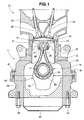
- an internal combustion engine 10 has a cylinder block 11, a piston 13 fitted movably in a cylinder bore 12 formed in the cylinder block 11, a connecting rod 16 coupled to the piston 13 by a spherical joint 14, and a crankshaft 18 attached rotatably to a lower portion of the cylinder block 11 and supporting the connecting rod 16 swingably by a hollow crank pin 17.
- the cylinder block 11 has a cylinder 21 formed in its upper portion, a cylindrical sleeve 22 fitted in the cylinder 21 and defining the cylinder bore 12 and an upper crankcase 23 attached to the bottom of the cylinder 21.
- Reference numeral 31 denotes a sliding bearing disposed between the big end 25 of the connecting rod 16 and the crank pin 17; 32, a counterweight on the crankshaft 18; 33, a cylinder head attached to the top of the cylinder block 11 with a head gasket disposed therebetween, but not shown; 34, an intake valve; 36, an exhaust valve; 37, a combustion chamber; 38, a lower crankcase secured to the bottom of the upper crankcase 23 by bolts 41 and forming a crankcase therewith; and 42, an oil pan secured to the bottom of the lower crankcase 38 by bolts 44.
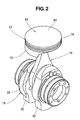
- FIG. 2 shows the connecting rod 16 coupled swingably to the piston 13 and the crankshaft 18.
- the piston 13 may, for example, be obtained by casting a material designated as AC8A [JIS H 5202], subjecting a casting to T6 heat treatment and machine finishing it.
- the connecting rod 16 is preferably formed from chromium or chromium-molybdenum steel, or a titanium alloy.
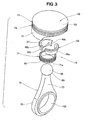
- FIG. 3 shows a structure in which a spherical small end 66 on the connecting rod 16 has an upper portion contacting the rear surface of the crown 65 of the piston 13 (which will be detailed later) and a lower portion held by a split holder 68 having two concave spherical surfaces 67 (of which only one is shown at 67), the holder 68 being attached to the rear surface of the crown 65 of the piston 13 by a nut 71.
- Reference numeral 69 denotes the spherical surface of the small end 66.
- the connecting rod 16 is formed by the small end 66, the annular big end 25 and a rod portion 73 joined to the small and big ends 66 and 25 integrally.
- the holder 68 is formed by two holder halves 68a. 68b denotes mating surfaces where the two holder halves 68a are mated.
- the holder 68 and the nut 71 are members forming a part of the spherical joint 14.
- the piston 13 is an integrally formed combination of the crown 65 shaped like a disk, a tubular land 74 extending downward from the edge of the crown 65 and having a large wall thickness, tubular skirts 75 extending downward from the land 74, having a smaller thickness than that of the land 74 and forming a tubular wall, a cup-shaped support 78 formed on the rear surface 77 of the crown 65 to form a concave semi-spherical surface 76 in which the small end 66 of the connecting rod 16 is slidably fitted and a plurality of ribs 81 extending between the land 74 and the cup-shaped support 78 and downward from the rear surface 77 of the crown 65.
- the crown 65 has a crown surface 83 defining a part of the combustion chamber 37 (see FIG. 1).
- the land 74 is a portion formed along the edge of the crown 65 and having a top land 74a, a top ring groove 74b, a second land 74c, a second ring groove 74d, a third land 74e and an oil ring groove 74f in the order mentioned as viewed from the crown surface 83, and a top ring is fitted in the top ring groove 74b, a second ring in the second ring groove 74d and an oil ring in the oil ring groove 74f.
- the cup-shaped support 78 has a downward recess 91 opening downwardly, the concave semi-spherical surface 76 formed in the bottom 92 of the downward recess 91 and a female thread 94 formed in the inner peripheral surface of the downward recess 91.
- the connecting rod 16 is swingably coupled to the piston 13 by having its small end 66 held against the concave semi-spherical surface 76, placing the holder 68 in the downward recess 91 to have the small end 66 of the connecting rod 16 held on the spherical surfaces 67 of the holder 68 and engaging a male thread 95 on the nut 71 with the female thread 94 of the cup-shaped support 78.
- cup-shaped support 78, holder 68, nut 71 and small end 66 form the spherical joint 14.
- the holder 68 is a member held against rotation relative to the cup-shaped support 78 by a stop pin not shown, and having a guide surface not shown, but abutting on the rod 73 to hold the piston 13 against rotation relative to the connecting rod 16.
- Each holder half 68a has a shoulder 68c and the nut 71 has its upper end held against the shoulder 68c to fix the holder half 68a in position.
- the nut 71 has the male thread 95 and a plurality of engaging recesses 71a formed around its outer peripheral surface adjacent to its lower end so that a tool may be engaged therein to turn the nut.
- the connecting rod 16 has hollows 96 to 100 in its big end 25 and rod portion 73 and a hollow 101 in its small end 66 to have its weight reduced and also has oil holes 103 to 105 through which oil can be supplied from a mounting hole 102 in its big end 25 to the sliding surfaces of the spherical joint 14.
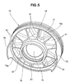
- FIG. 5 shows in detail the ribs 81 formed on the rear surface 77 of the crown 65 (see FIG. 4) of the piston 13 for connecting the land 74 and the cup-shaped support 78.
- the ribs 81 provide a rigid connection between the land 74 and the cup- shaped support 78 and thereby raise the rigidity of the upper portion of the piston 13.
- the individual ribs 81 may be small enough in thickness to suppress any undesirable increase in weight that they would otherwise give to the piston.
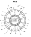
- FIG. 6 shows more clearly that the ribs 81 are formed radially between the inner surface 74g of the land 74 and the outer surface 78a of the cup-shaped support 78 in the piston 13.
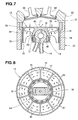
- the ribs 81 are formed on the rear surface 77 of the crown 65 (FIG. 7) radially at circumferentially equal intervals as shown in FIG. 8, it is possible to distribute the stress of the crown 65 uniformly to all the ribs 81 and thereby lower the maximum value of the stress.
- a high effect of heat dissipation owing to the release of heat through all the ribs 81 as shown by arrows in FIG. 8 makes it possible to lower the temperature of any part of the piston 13. Referring to FIG. 7, therefore, it is possible to lower the temperature of the spherical joint 14, or more particularly of the concave spherical surface 76 of the cup- shaped support 78 and thereby prevent the disappearance of any oil film from between the concave spherical surface 76 and the small end 66 of the connecting rod 16.
- the ribs 81 in the piston described above are formed integrally with the rear surface 77 of the crown 65, the cup-shaped support 78 and the land 74 as shown in FIG. 4, it is alternatively possible to form the ribs 81 in such a way that none or only a part of them may be connected with the rear surface 77 of the crown 65.
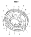
- FIG. 9 shows a plurality of ribs 81 formed on the rear surface 77 of the crown 65 (see FIG. 4) of a piston 13A according to another embodiment of this invention.
- the ribs 81 provide a rigid connection between a land 74 and a cup-shaped support 78 and thereby raise the rigidity of the upper portion of the piston 13A.
- the individual ribs 81 may be small enough in thickness to suppress any undesirable increase in weight that they would otherwise give to the piston.
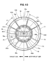
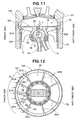
- FIG. 10 shows as the ribs 81 a plurality of ribs 81A and 81B formed radially between the inner surface 74g of the land 74 and the outer surface 78a of the cup-shaped support 78 in the piston 13A and in such a way that the ribs 81A formed on the thrust side of the piston 13A on the left hand of a piston centerline 13a extending at right angles to the swinging direction of the connecting rod 16 relative to the piston 13A, or the horizontal as viewed in the drawing, are asymmetric to the ribs 81B on the anti-thrust side of the piston 13A on the right hand of the piston centerline 13a. More specifically, the ribs 81B on the anti-thrust side are spaced apart from one another by a greater distance than the ribs 81A on the thrust side which are closer to one another are.
- the thrust R which is a reaction force from a sleeve 22 (see FIG. 1), acts upon the land 74T and skirt 75T of the piston 13A in the direction of arrows drawn by broken lines in FIG. 12, the ribs 81A on the thrust side produce reaction forces R1, R2 and R3 as shown by arrows to bear the thrust R.
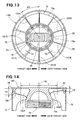
- FIG. 13 shows a plurality of ribs 181A and 181B formed radially between the inner surface 74g of a land 74 and the outer surface 78a of a cup-shaped support 78 in a piston 13B according to still another embodiment of this invention in such a way that the ribs 181A on the thrust side of the piston 13B are asymmetric to the ribs 181B on its anti-thrust side. More specifically, the ribs 181A on the thrust side are larger in thickness (wall thickness) than the ribs 181B on the anti-thrust side.
- each rib 181A on the thrust side is designated as T1 in FIG. 13, for example, T1 > T2 when the thickness (wall thickness) of each rib 181B on the anti-thrust side is T2.
- Every two adjoining ribs 181A, every two adjoining ribs 181A and 181B and every two adjoining ribs 181B have an equal angle ⁇ 3 therebetween.
- FIG. 14 shows a plurality of ribs 182A and 182B (outlined by thicker lines) formed radially between the inner surface 74g of a land 74 and the outer surface 78a of a cup-shaped support 78 in a piston 13C according to still another embodiment of this invention in such a way that the ribs 182A on the thrust side of the piston 13C are asymmetric to the ribs 182B on its anti-thrust side. More specifically, the ribs 182A on the thrust side are larger in height than the ribs 182B on the anti-thrust side.
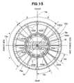
- FIG. 15 shows a plurality of ribs 183A and 183B formed radially between the inner surface 74g of a land 74 and the outer surface 78a of a cup-shaped support 78 in a piston 13D according to still another embodiment of this invention in such a way that the ribs 183A on the thrust and anti-thrust sides of the piston 13D are symmetric to each other, and that when that side which is shown above a horizontal piston centerline 13c crossing a vertical piston centerline 13a at right angles thereto is defined as the front side of the piston 13D corresponding to the front side of an internal combustion engine, while that side which is shown below the piston centerline 13c is defined as the rear side of the piston 13D corresponding to the rear side of the engine, the ribs 183B on the front and rear sides of the piston 13D are symmetric to each other, while the ribs 183A situated in an area having an angle ⁇ on either side of the piston centerline 13c on both of the thrust and anti-thrust sides are closer to
- radial ribs have been described as being asymmetric to each other on the thrust and anti-thrust sides of the piston, it is alternatively possible to form those ribs in such a way that they may be asymmetric to each other on the front and rear sides of the piston.
- a piston (13) for an internal combustion engine includes a crown (65), tubular walls (74, 75) extending from an edge of the crown and a cup portion (78) protruding from a rear surface (77) of the crown and having a concave spherical surface (76) for forming a spherical joint (14) with a spherical small end (66) on a connecting rod (16).
- the tubular walls and the cup portion are joined together by radially extending ribs.
Landscapes
- Engineering & Computer Science (AREA)
- General Engineering & Computer Science (AREA)
- Chemical & Material Sciences (AREA)
- Combustion & Propulsion (AREA)
- Mechanical Engineering (AREA)
- Pistons, Piston Rings, And Cylinders (AREA)
Applications Claiming Priority (4)
| Application Number | Priority Date | Filing Date | Title |
|---|---|---|---|
| JP2003369311A JP2005133613A (ja) | 2003-10-29 | 2003-10-29 | 内燃機関用ピストン |
| JP2003369311 | 2003-10-29 | ||
| JP2004153347A JP2005337027A (ja) | 2004-05-24 | 2004-05-24 | 内燃機関用ピストン |
| JP2004153347 | 2004-05-24 |
Publications (2)
| Publication Number | Publication Date |
|---|---|
| EP1528245A1 true EP1528245A1 (de) | 2005-05-04 |
| EP1528245B1 EP1528245B1 (de) | 2007-08-15 |
Family
ID=34425405
Family Applications (1)
| Application Number | Title | Priority Date | Filing Date |
|---|---|---|---|
| EP04025799A Expired - Lifetime EP1528245B1 (de) | 2003-10-29 | 2004-10-29 | Kolben für einen Verbrennungsmotor |
Country Status (3)
| Country | Link |
|---|---|
| US (1) | US7086368B2 (de) |
| EP (1) | EP1528245B1 (de) |
| DE (1) | DE602004008184T2 (de) |
Cited By (5)
| Publication number | Priority date | Publication date | Assignee | Title |
|---|---|---|---|---|
| EP1529991B1 (de) * | 2003-11-07 | 2007-07-04 | HONDA MOTOR CO., Ltd. | Gelenkverbindung zwischen Kolben und Pleuel |
| EP1722114A3 (de) * | 2005-05-11 | 2008-05-14 | O. St. Feingussgesellschaft m. b. H. | Hochrobuste, leichtgewichtige Pleuelstange |
| EP1529992B1 (de) * | 2003-11-07 | 2008-11-26 | Honda Motor Co., Ltd. | Brennkraftmaschine und Pleuelstange dafür |
| EP1818531A3 (de) * | 2006-02-09 | 2009-09-30 | HONDA MOTOR CO., Ltd. | Kolben für einen Verbrennungsmotor |
| DE102006033293B4 (de) | 2006-07-17 | 2023-08-10 | Anatoliy Levitan | Zylinder-Kolben-Anordnung |
Families Citing this family (5)
| Publication number | Priority date | Publication date | Assignee | Title |
|---|---|---|---|---|
| JP4165506B2 (ja) * | 2004-12-28 | 2008-10-15 | 日産自動車株式会社 | 内燃機関 |
| KR100735091B1 (ko) * | 2005-02-04 | 2007-07-03 | 콜브 한스 피터 | 피스톤과 커넥팅 로드 조립체 |
| USD590722S1 (en) * | 2007-07-06 | 2009-04-21 | Mcgrath Joseph | Piston container |
| WO2012001887A1 (en) | 2010-06-29 | 2012-01-05 | Kolbenschmidt K.K. | Piston for spark-ignition engine |
| CN105051357B (zh) | 2013-01-21 | 2018-05-18 | 费德罗-莫格尔公司 | 活塞及其制造方法 |
Citations (10)
| Publication number | Priority date | Publication date | Assignee | Title |
|---|---|---|---|---|
| US1401075A (en) * | 1921-03-07 | 1921-12-20 | Hartwig George | Piston-rod connection |
| GB308905A (en) * | 1928-04-18 | 1929-04-04 | John Frederick Hammond | A new and improved application of ball bearings to engines, steering gear and the like |
| DE881591C (de) * | 1951-01-17 | 1953-07-02 | Daimler Benz Ag | Kolben mit kugeligem Pleuellager |
| FR1083390A (fr) * | 1952-10-14 | 1955-01-07 | Su Dwerke Motoren Und Kraftwag | Piston pour moteur à combustion interne, notamment pour moteur à deux temps |
| JPH09144879A (ja) | 1995-11-28 | 1997-06-03 | Kubota Corp | エンジンのピストン・コンロッド球面連結装置 |
| JPH1078130A (ja) * | 1996-09-03 | 1998-03-24 | Toyota Motor Corp | 内燃機関のピストン |
| JP2000039066A (ja) * | 1998-07-23 | 2000-02-08 | Toyota Motor Corp | ピストン |
| JP2000097105A (ja) | 1998-09-22 | 2000-04-04 | Yamaha Motor Co Ltd | 内燃機関用ピストン |
| JP2000213646A (ja) | 1999-01-28 | 2000-08-02 | Toyota Motor Corp | ピストンとコンロッドの組み付け構造 |
| JP2002317693A (ja) * | 2001-04-20 | 2002-10-31 | Unisia Jecs Corp | 内燃機関のピストン |
Family Cites Families (11)
| Publication number | Priority date | Publication date | Assignee | Title |
|---|---|---|---|---|
| US1763523A (en) * | 1920-03-11 | 1930-06-10 | Cleveland Trust Co | Piston |
| US1482675A (en) * | 1921-10-31 | 1924-02-05 | Charles Lawrence Wells | Pistom |
| DE398181C (de) * | 1923-03-07 | 1924-07-11 | Dante Sferino Cantoni | Kolben fuer Verbrennungskraftmaschinen |
| US3069210A (en) * | 1960-10-17 | 1962-12-18 | Argel A Rogers | Piston mounting means |
| US4372179A (en) * | 1978-01-25 | 1983-02-08 | Steyr-Daimler-Puch Aktiengesellschaft | Reciprocating-piston drive mechanism |
| US4765292A (en) * | 1985-08-19 | 1988-08-23 | Morgado Ralph G | Self-sealing piston apparatus |
| FR2660698B1 (fr) * | 1990-04-06 | 1994-07-08 | Melchior Jean | Piston pour moteurs a combustion interne et machines analogues. |
| DE4016723A1 (de) * | 1990-05-24 | 1991-11-28 | Kolbenschmidt Ag | Kolben-pleuel-anordnung |
| US5669285A (en) * | 1996-02-07 | 1997-09-23 | Cummins Engine Company, Inc. | Spherical joint connecting rod holder rings |
| JPH11303674A (ja) * | 1998-04-24 | 1999-11-02 | Unisia Jecs Corp | 内燃機関のピストン |
| GB9908844D0 (en) * | 1999-04-19 | 1999-06-16 | Seneca Tech Ltd | Piston-connecting rod retention |
-
2004
- 2004-10-28 US US10/974,716 patent/US7086368B2/en not_active Expired - Fee Related
- 2004-10-29 EP EP04025799A patent/EP1528245B1/de not_active Expired - Lifetime
- 2004-10-29 DE DE602004008184T patent/DE602004008184T2/de not_active Expired - Lifetime
Patent Citations (10)
| Publication number | Priority date | Publication date | Assignee | Title |
|---|---|---|---|---|
| US1401075A (en) * | 1921-03-07 | 1921-12-20 | Hartwig George | Piston-rod connection |
| GB308905A (en) * | 1928-04-18 | 1929-04-04 | John Frederick Hammond | A new and improved application of ball bearings to engines, steering gear and the like |
| DE881591C (de) * | 1951-01-17 | 1953-07-02 | Daimler Benz Ag | Kolben mit kugeligem Pleuellager |
| FR1083390A (fr) * | 1952-10-14 | 1955-01-07 | Su Dwerke Motoren Und Kraftwag | Piston pour moteur à combustion interne, notamment pour moteur à deux temps |
| JPH09144879A (ja) | 1995-11-28 | 1997-06-03 | Kubota Corp | エンジンのピストン・コンロッド球面連結装置 |
| JPH1078130A (ja) * | 1996-09-03 | 1998-03-24 | Toyota Motor Corp | 内燃機関のピストン |
| JP2000039066A (ja) * | 1998-07-23 | 2000-02-08 | Toyota Motor Corp | ピストン |
| JP2000097105A (ja) | 1998-09-22 | 2000-04-04 | Yamaha Motor Co Ltd | 内燃機関用ピストン |
| JP2000213646A (ja) | 1999-01-28 | 2000-08-02 | Toyota Motor Corp | ピストンとコンロッドの組み付け構造 |
| JP2002317693A (ja) * | 2001-04-20 | 2002-10-31 | Unisia Jecs Corp | 内燃機関のピストン |
Non-Patent Citations (4)
| Title |
|---|
| PATENT ABSTRACTS OF JAPAN vol. 1998, no. 08 30 June 1998 (1998-06-30) * |
| PATENT ABSTRACTS OF JAPAN vol. 2000, no. 05 14 September 2000 (2000-09-14) * |
| PATENT ABSTRACTS OF JAPAN vol. 2000, no. 07 29 September 2000 (2000-09-29) * |
| PATENT ABSTRACTS OF JAPAN vol. 2003, no. 02 5 February 2003 (2003-02-05) * |
Cited By (5)
| Publication number | Priority date | Publication date | Assignee | Title |
|---|---|---|---|---|
| EP1529991B1 (de) * | 2003-11-07 | 2007-07-04 | HONDA MOTOR CO., Ltd. | Gelenkverbindung zwischen Kolben und Pleuel |
| EP1529992B1 (de) * | 2003-11-07 | 2008-11-26 | Honda Motor Co., Ltd. | Brennkraftmaschine und Pleuelstange dafür |
| EP1722114A3 (de) * | 2005-05-11 | 2008-05-14 | O. St. Feingussgesellschaft m. b. H. | Hochrobuste, leichtgewichtige Pleuelstange |
| EP1818531A3 (de) * | 2006-02-09 | 2009-09-30 | HONDA MOTOR CO., Ltd. | Kolben für einen Verbrennungsmotor |
| DE102006033293B4 (de) | 2006-07-17 | 2023-08-10 | Anatoliy Levitan | Zylinder-Kolben-Anordnung |
Also Published As
| Publication number | Publication date |
|---|---|
| EP1528245B1 (de) | 2007-08-15 |
| DE602004008184D1 (de) | 2007-09-27 |
| US7086368B2 (en) | 2006-08-08 |
| US20050092280A1 (en) | 2005-05-05 |
| DE602004008184T2 (de) | 2008-05-08 |
Similar Documents
| Publication | Publication Date | Title |
|---|---|---|
| US10151269B2 (en) | Mass efficient piston | |
| CN107257885B (zh) | 减小压缩高度的双通道活塞、其活塞组件及其构建方法 | |
| KR101283956B1 (ko) | 향상된 냉각 특성을 갖는 피스톤 | |
| JP2005507042A (ja) | モノブロックピストン | |
| EP1528245B1 (de) | Kolben für einen Verbrennungsmotor | |
| US10428761B2 (en) | Galleryless piston with improved pocket cooling | |
| US4515112A (en) | Aluminum alloy cylinder block | |
| US10344706B2 (en) | Galleryless piston with cutout above pin bore | |
| EP1529992B1 (de) | Brennkraftmaschine und Pleuelstange dafür | |
| CN105209736A (zh) | 活塞及其构造方法 | |
| JP2019508624A (ja) | スロット付きリング溝を有する空洞なしのピストン | |
| JPH07166955A (ja) | シリンダライナ支持装置 | |
| US9470311B2 (en) | Lightweight engine power cell assembly | |
| KR20140123083A (ko) | 피스톤 및 냉각되는 피스톤 링과 그 제작 방법 | |
| KR100303903B1 (ko) | 엔진의실린더블록구조 | |
| JP4256790B2 (ja) | ガスエンジンのピストン | |
| US7290518B2 (en) | Piston-connecting rod spherical coupling structure | |
| JP2010164030A (ja) | 内燃機関用ピストン | |
| US5937803A (en) | Engine cylinder block | |
| JP2004360603A (ja) | 内燃機関の冷却装置 | |
| JP2005133613A (ja) | 内燃機関用ピストン | |
| JP5307209B2 (ja) | 内燃機関のピストン | |
| US20170254292A1 (en) | Galleryless piston with oil drain features | |
| JP2019507283A (ja) | ポケットに対する接続を有する空洞なしのピストン | |
| JP2005188303A (ja) | エンジンのピストン構造 |
Legal Events
| Date | Code | Title | Description |
|---|---|---|---|
| PUAI | Public reference made under article 153(3) epc to a published international application that has entered the european phase |
Free format text: ORIGINAL CODE: 0009012 |
|
| AK | Designated contracting states |
Kind code of ref document: A1 Designated state(s): AT BE BG CH CY CZ DE DK EE ES FI FR GB GR HU IE IT LI LU MC NL PL PT RO SE SI SK TR |
|
| AX | Request for extension of the european patent |
Extension state: AL HR LT LV MK |
|
| 17P | Request for examination filed |
Effective date: 20050519 |
|
| AKX | Designation fees paid |
Designated state(s): DE FR GB |
|
| GRAP | Despatch of communication of intention to grant a patent |
Free format text: ORIGINAL CODE: EPIDOSNIGR1 |
|
| GRAS | Grant fee paid |
Free format text: ORIGINAL CODE: EPIDOSNIGR3 |
|
| GRAA | (expected) grant |
Free format text: ORIGINAL CODE: 0009210 |
|
| AK | Designated contracting states |
Kind code of ref document: B1 Designated state(s): DE FR GB |
|
| REG | Reference to a national code |
Ref country code: GB Ref legal event code: FG4D |
|
| RIN1 | Information on inventor provided before grant (corrected) |
Inventor name: NAKATA, MASAKIC/O HONDA R&D CO., LTD. Inventor name: ISHIMITSU, KENGOC/O HONDA R&D CO., LTD. Inventor name: INOUE, TSUTOMUC/O HONDA R&D CO., LTD. Inventor name: ENDOH, TSUNEOC/O HONDA R&D CO., LTD. |
|
| REF | Corresponds to: |
Ref document number: 602004008184 Country of ref document: DE Date of ref document: 20070927 Kind code of ref document: P |
|
| ET | Fr: translation filed | ||
| PLBE | No opposition filed within time limit |
Free format text: ORIGINAL CODE: 0009261 |
|
| STAA | Information on the status of an ep patent application or granted ep patent |
Free format text: STATUS: NO OPPOSITION FILED WITHIN TIME LIMIT |
|
| 26N | No opposition filed |
Effective date: 20080516 |
|
| PGFP | Annual fee paid to national office [announced via postgrant information from national office to epo] |
Ref country code: DE Payment date: 20091022 Year of fee payment: 6 |
|
| PGFP | Annual fee paid to national office [announced via postgrant information from national office to epo] |
Ref country code: FR Payment date: 20091029 Year of fee payment: 6 Ref country code: GB Payment date: 20091028 Year of fee payment: 6 |
|
| GBPC | Gb: european patent ceased through non-payment of renewal fee |
Effective date: 20101029 |
|
| PG25 | Lapsed in a contracting state [announced via postgrant information from national office to epo] |
Ref country code: FR Free format text: LAPSE BECAUSE OF NON-PAYMENT OF DUE FEES Effective date: 20101102 |
|
| REG | Reference to a national code |
Ref country code: FR Ref legal event code: ST Effective date: 20110630 |
|
| PG25 | Lapsed in a contracting state [announced via postgrant information from national office to epo] |
Ref country code: GB Free format text: LAPSE BECAUSE OF NON-PAYMENT OF DUE FEES Effective date: 20101029 |
|
| REG | Reference to a national code |
Ref country code: DE Ref legal event code: R119 Ref document number: 602004008184 Country of ref document: DE Effective date: 20110502 |
|
| PG25 | Lapsed in a contracting state [announced via postgrant information from national office to epo] |
Ref country code: DE Free format text: LAPSE BECAUSE OF NON-PAYMENT OF DUE FEES Effective date: 20110502 |