EP1528210A2 - Dispositif d' ajustage pour un élément de construction - Google Patents
Dispositif d' ajustage pour un élément de construction Download PDFInfo
- Publication number
- EP1528210A2 EP1528210A2 EP04025783A EP04025783A EP1528210A2 EP 1528210 A2 EP1528210 A2 EP 1528210A2 EP 04025783 A EP04025783 A EP 04025783A EP 04025783 A EP04025783 A EP 04025783A EP 1528210 A2 EP1528210 A2 EP 1528210A2
- Authority
- EP
- European Patent Office
- Prior art keywords
- sleeve
- bolt
- threaded pin
- building
- adjusting
- Prior art date
- Legal status (The legal status is an assumption and is not a legal conclusion. Google has not performed a legal analysis and makes no representation as to the accuracy of the status listed.)
- Withdrawn
Links
- 238000010276 construction Methods 0.000 title 1
- 238000004519 manufacturing process Methods 0.000 description 2
- 238000006073 displacement reaction Methods 0.000 description 1
- 238000004513 sizing Methods 0.000 description 1
- 239000007787 solid Substances 0.000 description 1
Images
Classifications
-
- E—FIXED CONSTRUCTIONS
- E06—DOORS, WINDOWS, SHUTTERS, OR ROLLER BLINDS IN GENERAL; LADDERS
- E06B—FIXED OR MOVABLE CLOSURES FOR OPENINGS IN BUILDINGS, VEHICLES, FENCES OR LIKE ENCLOSURES IN GENERAL, e.g. DOORS, WINDOWS, BLINDS, GATES
- E06B1/00—Border constructions of openings in walls, floors, or ceilings; Frames to be rigidly mounted in such openings
- E06B1/56—Fastening frames to the border of openings or to similar contiguous frames
- E06B1/60—Fastening frames to the border of openings or to similar contiguous frames by mechanical means, e.g. anchoring means
- E06B1/6069—Separate spacer means acting exclusively in the plane of the opening; Shims; Wedges; Tightening of a complete frame inside a wall opening
- E06B1/6076—Separate spacer means acting exclusively in the plane of the opening; Shims; Wedges; Tightening of a complete frame inside a wall opening of screw-type
-
- E—FIXED CONSTRUCTIONS
- E06—DOORS, WINDOWS, SHUTTERS, OR ROLLER BLINDS IN GENERAL; LADDERS
- E06B—FIXED OR MOVABLE CLOSURES FOR OPENINGS IN BUILDINGS, VEHICLES, FENCES OR LIKE ENCLOSURES IN GENERAL, e.g. DOORS, WINDOWS, BLINDS, GATES
- E06B1/00—Border constructions of openings in walls, floors, or ceilings; Frames to be rigidly mounted in such openings
- E06B1/56—Fastening frames to the border of openings or to similar contiguous frames
- E06B1/60—Fastening frames to the border of openings or to similar contiguous frames by mechanical means, e.g. anchoring means
- E06B1/6069—Separate spacer means acting exclusively in the plane of the opening; Shims; Wedges; Tightening of a complete frame inside a wall opening
Definitions
- the invention relates to a device for adjusting a Building, in particular a window frame, in one Building opening with an adjusting element containing a Bolt, which is attached to a building and in itself in a receiving bore of the same extending sleeve is mounted axially displaceable, and that the bolt on a side facing away from the building with a support element is rigidly connected.
- From DE 102 08 362 A1 is already a device for Adjusting a building known in which an adjustment is formed of a bolt and a sleeve.
- the Sleeve is arranged in a receiving bore of the building and fastened thereto by means of fastening means.
- the bolt has a threaded portion in the circumferential direction and a non-threaded portion. hereby can the bolt in a simple manner depending from the rotational position of the same move in the axial direction and then set.
- the known adjusting element which has proven itself in practice, points However, the disadvantage that the effort to manufacture of the adjusting element is relatively high.
- the object of the present invention is a device for adjusting a building in a building opening in such a way that the manufacturing technology Effort to provide the adjustment simplified becomes.
- the device is in communication characterized by the preamble of claim 1, characterized that the sleeve on a the support element facing side outside the building a radial bore having an internal thread, such that they are with a radially displaceable threaded pin in screw engagement can be brought to the axial fixing of the bolt.
- the particular advantage of the invention is that a bolt of the adjusting element a simple geometric Form or have a homogeneous surface structure can.
- the outside diameter of the bolt is something smaller than the inner diameter of the sleeve, so that an axial displacement of the bolt made sliding can.
- a radial bore of the sleeve is movable and in the locked position clamp the bolt in the sleeve.
- the bolt is cylindrical formed with smooth lateral surfaces.
- To the Adjust it is slidably mounted slidably in the sleeve.
- the sleeve is by means of two sleeve wings from the outside attached to the building. This is a secure positioning the sleeve in a receiving bore of the building guaranteed.
- a preferred embodiment of the invention has the grub screw at a free end an Allen socket on, so that by means of a Allen key a secure Twisting or tightening of the bolt is made possible.
- the bolt also be provided with an external thread, so that the sleeve in the locking position by means of a lock nut is clamped. This results in a improved mechanical strength between the sleeve and the bolt, so that higher mechanical demands on the Anchor (WK2 assembly) can be met.
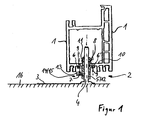
- a device for adjusting one as a window frame 1 trained structure consists essentially of a multi-part adjusting element 2.
- the adjusting element 2 consists on the one hand of an integral with a support element 3 connected bolts 4.
- the adjusting element 2 is made on the other hand from a sleeve 5, which is integral with Sleeve wings 6, 6 'is connected.
- points the adjusting element 2 a threaded pin 7 for clamping of the bolt 4 in the sleeve 5 in the locking position.
- the sleeve 5 is in a for provided receiving bore 8 of the window frame 1 in a Fixed position spent.
- two not shown screws through holes 9 of the sleeve wings 6, 6 'through walls of the plastic hollow profile. 1 screwed in, so that a non-positive or positive Connection between the sleeve 5 and the plastic hollow profile 1 is given.
- the sleeve 5 with an inner Sleeve portion 11 within the cavity of the window frame 1 and with an outer sleeve portion 12 outside of the hollow profile 1 is arranged.
- the sleeve 5 has such an inner diameter that the bolt 4 for Adjusting sliding in the sleeve 5 is displaced.
- a tool holder 15 is arranged be, preferably a Allen, so that by means of a Allen key causes a rotation of the threaded pin 7 can be.
- the degree of axial fixing of the bolt 4 be set.
- the bolt 4 has a smooth lateral surface. He is designed as a solid cylinder and has a cross section circular shape up.
- the support element 3 After the bolt 4 has been brought into the locked position is, by pivoting the support element 3 to the central axis of the bolt 4 a desired position of the support element 3 be taken.
- a desired position of the support element 3 be taken.
- the support element 3 partially one or more holes or oblong holes.
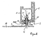
- a second embodiment of the invention according to FIG 2 is different from the previous embodiment the lateral surface of a bolt 4 'of the adjusting element 2 provided with an external thread 20.
- a lock nut 21 for additionally fixing the bolt 4 'in the sleeve 5 serves.
- the determination of the bolt 4 'in the sleeve 5 is according to this embodiment, on the one hand Screw in the transverse to the bolt 4 'extending threaded pin 7 allows.
- the sleeve 5 can also be reversed on the bolt 4, 4 'applied.
- the extends Grub screw 7 in an area within the window frame 1 and the lock nut 21 outside the window frame 1.
Landscapes
- Engineering & Computer Science (AREA)
- Mechanical Engineering (AREA)
- Civil Engineering (AREA)
- Structural Engineering (AREA)
- Door And Window Frames Mounted To Openings (AREA)
Applications Claiming Priority (2)
| Application Number | Priority Date | Filing Date | Title |
|---|---|---|---|
| DE20316768U | 2003-10-30 | ||
| DE20316768U DE20316768U1 (de) | 2003-10-30 | 2003-10-30 | Vorrichtung zum Justieren eines Baukörpers |
Publications (2)
| Publication Number | Publication Date |
|---|---|
| EP1528210A2 true EP1528210A2 (fr) | 2005-05-04 |
| EP1528210A3 EP1528210A3 (fr) | 2006-08-23 |
Family
ID=30129085
Family Applications (1)
| Application Number | Title | Priority Date | Filing Date |
|---|---|---|---|
| EP04025783A Withdrawn EP1528210A3 (fr) | 2003-10-30 | 2004-10-29 | Dispositif d' ajustage pour un élément de construction |
Country Status (2)
| Country | Link |
|---|---|
| EP (1) | EP1528210A3 (fr) |
| DE (1) | DE20316768U1 (fr) |
Cited By (2)
| Publication number | Priority date | Publication date | Assignee | Title |
|---|---|---|---|---|
| DE102010014036A1 (de) * | 2010-04-06 | 2011-10-06 | Chempe Gmbh & Co. Kg | Verbindung |
| WO2025021932A1 (fr) * | 2023-07-27 | 2025-01-30 | Konczak Jens | Aide à l'alignement pour un profilé de cadre |
Families Citing this family (1)
| Publication number | Priority date | Publication date | Assignee | Title |
|---|---|---|---|---|
| CN104790808B (zh) * | 2015-04-23 | 2016-09-07 | 李毅 | 门窗组件 |
Citations (1)
| Publication number | Priority date | Publication date | Assignee | Title |
|---|---|---|---|---|
| DE10208362A1 (de) | 2002-02-27 | 2003-09-11 | Waldemar Knelsen | Vorrichtung zum Justieren eines Baukörpers und ein Justierverfahren |
Family Cites Families (3)
| Publication number | Priority date | Publication date | Assignee | Title |
|---|---|---|---|---|
| DE29605603U1 (de) * | 1996-03-26 | 1996-05-30 | Kalvelage, Michael, 49393 Lohne | Vorrichtung für die Montage von Türen und/oder Fenstern in Gebäudeöffnungen |
| DE19631016A1 (de) * | 1996-08-01 | 1998-02-05 | Harry Frey | Türschwelle mit Montagevorrichtung |
| DE20005485U1 (de) * | 2000-03-23 | 2000-06-21 | Romberger, Jan, 99518 Bad Sulza | Ausrichtungsvorrichtung für die Montage von Fenstern, Türen u.dgl. |
-
2003
- 2003-10-30 DE DE20316768U patent/DE20316768U1/de not_active Expired - Lifetime
-
2004
- 2004-10-29 EP EP04025783A patent/EP1528210A3/fr not_active Withdrawn
Patent Citations (1)
| Publication number | Priority date | Publication date | Assignee | Title |
|---|---|---|---|---|
| DE10208362A1 (de) | 2002-02-27 | 2003-09-11 | Waldemar Knelsen | Vorrichtung zum Justieren eines Baukörpers und ein Justierverfahren |
Cited By (2)
| Publication number | Priority date | Publication date | Assignee | Title |
|---|---|---|---|---|
| DE102010014036A1 (de) * | 2010-04-06 | 2011-10-06 | Chempe Gmbh & Co. Kg | Verbindung |
| WO2025021932A1 (fr) * | 2023-07-27 | 2025-01-30 | Konczak Jens | Aide à l'alignement pour un profilé de cadre |
Also Published As
| Publication number | Publication date |
|---|---|
| EP1528210A3 (fr) | 2006-08-23 |
| DE20316768U1 (de) | 2004-01-08 |
Similar Documents
| Publication | Publication Date | Title |
|---|---|---|
| DE69302477T2 (de) | Verbindungsvorrichtung | |
| EP1426636B1 (fr) | Ecrou de support rapide | |
| EP2146813B1 (fr) | Adaptateur pour faire fonctionner une scie cloche sur une machine d'entraînement | |
| DE29708384U1 (de) | Mit der Antriebswelle einer Drehmaschine kuppelbares Werkzeugsystem | |
| WO1998058180A1 (fr) | Ensemble de vissage | |
| DE2405262A1 (de) | Spannschraube | |
| DE2239853B2 (de) | Haltevorrichtung fuer aussenrueckblickspiegel von kraftfahrzeugen o.dgl. | |
| EP0485757A1 (fr) | Jeu d'éléments pour la construction de poignées, mains courantes, barrières, petits meubles ou analogues | |
| DE3300006A1 (de) | Scharnierbefestigung fuer kraftwagentueren | |
| DE202022101626U1 (de) | Vorrichtung zur Begrenzung der Eingriffstiefe eines Zerspanungswerkzeugs | |
| EP2097199B1 (fr) | Dispositif pendulaire et procédé associé | |
| CH645700A5 (de) | Vorrichtung zum loesbaren verbinden zweier hohlprofilkoerper. | |
| DE2615322C2 (de) | Befestigungsvorrichtung für Türschilder bzw. Türrosetten | |
| EP1528210A2 (fr) | Dispositif d' ajustage pour un élément de construction | |
| DE102008049828B4 (de) | Bandbefestigungsteil | |
| DE3142474C2 (fr) | ||
| DE202006002876U1 (de) | Vorrichtung zum Justieren eines Baukörpers | |
| EP0512230A2 (fr) | Dispositif interchangeable pour mâchoirs de serrage de mandrin de tour | |
| DE10208362A1 (de) | Vorrichtung zum Justieren eines Baukörpers und ein Justierverfahren | |
| DE3437089A1 (de) | Klemmvorrichtung | |
| DE202007008969U1 (de) | Profilverbinder sowie Profilverbund | |
| EP3865717A1 (fr) | Montant télescopique | |
| EP1388628A2 (fr) | Charnière avec un dispositif de levage et d'abaissement réglable en hauteur et en angle pour portes et fenêtres | |
| EP4054790B1 (fr) | Ensemble table à transfert circulaire pouvant être mis en place sans outil | |
| EP1598213B1 (fr) | Compas blocable avec dispositif d'adjustement rapide |
Legal Events
| Date | Code | Title | Description |
|---|---|---|---|
| PUAI | Public reference made under article 153(3) epc to a published international application that has entered the european phase |
Free format text: ORIGINAL CODE: 0009012 |
|
| AK | Designated contracting states |
Kind code of ref document: A2 Designated state(s): AT BE BG CH CY CZ DE DK EE ES FI FR GB GR HU IE IT LI LU MC NL PL PT RO SE SI SK TR |
|
| AX | Request for extension of the european patent |
Extension state: AL HR LT LV MK |
|
| PUAL | Search report despatched |
Free format text: ORIGINAL CODE: 0009013 |
|
| AK | Designated contracting states |
Kind code of ref document: A3 Designated state(s): AT BE BG CH CY CZ DE DK EE ES FI FR GB GR HU IE IT LI LU MC NL PL PT RO SE SI SK TR |
|
| AX | Request for extension of the european patent |
Extension state: AL HR LT LV MK |
|
| AKX | Designation fees paid | ||
| STAA | Information on the status of an ep patent application or granted ep patent |
Free format text: STATUS: THE APPLICATION IS DEEMED TO BE WITHDRAWN |
|
| 18D | Application deemed to be withdrawn |
Effective date: 20070224 |
|
| REG | Reference to a national code |
Ref country code: DE Ref legal event code: 8566 |