EP1528134A2 - Vorrichtung und Verfahren zur Behandlung eines laufenden Fadens mit einem dampfförmigen Behandlungsmedium - Google Patents
Vorrichtung und Verfahren zur Behandlung eines laufenden Fadens mit einem dampfförmigen Behandlungsmedium Download PDFInfo
- Publication number
- EP1528134A2 EP1528134A2 EP04022253A EP04022253A EP1528134A2 EP 1528134 A2 EP1528134 A2 EP 1528134A2 EP 04022253 A EP04022253 A EP 04022253A EP 04022253 A EP04022253 A EP 04022253A EP 1528134 A2 EP1528134 A2 EP 1528134A2
- Authority
- EP
- European Patent Office
- Prior art keywords
- chamber
- steam
- thread
- chambers
- cooling
- Prior art date
- Legal status (The legal status is an assumption and is not a legal conclusion. Google has not performed a legal analysis and makes no representation as to the accuracy of the status listed.)
- Granted
Links
Images
Classifications
-
- D—TEXTILES; PAPER
- D02—YARNS; MECHANICAL FINISHING OF YARNS OR ROPES; WARPING OR BEAMING
- D02J—FINISHING OR DRESSING OF FILAMENTS, YARNS, THREADS, CORDS, ROPES OR THE LIKE
- D02J13/00—Heating or cooling the yarn, thread, cord, rope, or the like, not specific to any one of the processes provided for in this subclass
- D02J13/001—Heating or cooling the yarn, thread, cord, rope, or the like, not specific to any one of the processes provided for in this subclass in a tube or vessel
-
- D—TEXTILES; PAPER
- D06—TREATMENT OF TEXTILES OR THE LIKE; LAUNDERING; FLEXIBLE MATERIALS NOT OTHERWISE PROVIDED FOR
- D06B—TREATING TEXTILE MATERIALS USING LIQUIDS, GASES OR VAPOURS
- D06B23/00—Component parts, details, or accessories of apparatus or machines, specially adapted for the treating of textile materials, not restricted to a particular kind of apparatus, provided for in groups D06B1/00 - D06B21/00
- D06B23/14—Containers, e.g. vats
- D06B23/18—Sealing arrangements
-
- D—TEXTILES; PAPER
- D06—TREATMENT OF TEXTILES OR THE LIKE; LAUNDERING; FLEXIBLE MATERIALS NOT OTHERWISE PROVIDED FOR
- D06B—TREATING TEXTILE MATERIALS USING LIQUIDS, GASES OR VAPOURS
- D06B3/00—Passing of textile materials through liquids, gases or vapours to effect treatment, e.g. washing, dyeing, bleaching, sizing, impregnating
- D06B3/04—Passing of textile materials through liquids, gases or vapours to effect treatment, e.g. washing, dyeing, bleaching, sizing, impregnating of yarns, threads or filaments
- D06B3/045—Passing of textile materials through liquids, gases or vapours to effect treatment, e.g. washing, dyeing, bleaching, sizing, impregnating of yarns, threads or filaments in a tube or a groove
Definitions
- the invention relates to a device for the treatment of a running thread with a pressurized vapor treatment medium.
- These Device can serve in particular as a heat-setting device, in which the Running thread heated in a steam treatment zone and then in a Cooling and drying zone is cooled and dried so that it is in his maintains the steam treatment zone reached state.
- steam is representative of other gaseous media.
- the aim of such treatment is, by a defined shrinkage or Elongation to influence and increase the volume or density of a textile thread control, for example, by a targeted shrinkage, the volume of Textile thread, the so-called Bausch, can be increased. It is essential that the Optimization and conservation of the thread in the steam treatment zone granted physical effects by cooling and drying of the treated Thread as fully as possible, even during and after the Winding the thread into a spool.
- EP 1 348 785 discloses a device for treating a running suture described with a vaporous treatment medium.
- This device contains several columnar superimposed thread treatment sections and chambers.
- An essential element of this device is the actual one steam treatment line provided with a steam inlet, the separation chambers upstream and downstream, the air inlets and condensate outlets have.
- the thread inlet and thread outlet channels of these chambers have an opening cross-section have the exchange of air and steam between the Chambers so regulates that in these separation chambers, a vapor-air mixed atmosphere adjusts the entry of air into the steam treatment room largely prevented.
- Separation chamber closes a cooling section in the form of a relatively narrow yarn path on, can be blown into the cooling air.
- the disadvantage of these known Device is that the cooling air supply in a relatively large Distance is done behind the steam treatment line and the cooling also takes place in a very narrow channel, so that the cooling and drying effect only is very low. This is due to the fact that the injected cooling air over a greater distance counter to the thread running direction in the direction of the steam treatment line must flow, so that there is no spontaneous cooling or Deterrence of the thread comes behind the steam treatment line. It is questioned to what extent in the downstream of the steam treatment line Separating and mixing chamber at all a condensation and so that a condensate separation is possible because the cooling air inlet via a relatively large distance only through the relatively narrow yarn path channel with this Separation chamber is in communication.
- the invention is based on the object, a device of EP 1 348 785 A1 type so that after steam treatment from the device emerging thread is cooled and dried so far that during and after winding into a bobbin the thread quality deteriorates State changes are largely excluded.
- the device according to the invention consists of several in particular vertically arranged one above the other, with steam or compressed air acted upon chambers, wherein adjacent chambers each arranged by means of centrally superimposed Fadeneinlauf- and thread outlet channels are connected to each other, whose Opening cross-sections are designed so that on the one hand pneumatic thread threading through the thread inlet and thread outlet channels all Chambers is possible, while on the other hand, an ingress of air from the the steam treatment chamber adjacent chambers largely excluded should be.
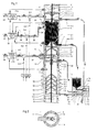
- the device includes an upper pre-chamber 3, in which a delivery mechanism 11 for the Thread F is housed.
- a prechamber 3 On the prechamber 3 is followed by a preferably heat-insulating material, in particular ceramic material, existing mixing chamber 4, which has an air inlet 4.1 and a condensate outlet 4.2.
- a steam treatment chamber 5 On the mixing chamber 4 is followed by a steam treatment chamber 5, which has a steam inlet 5.1 and a closable condensate outlet has 5.2.
- On the steam treatment chamber 5 follows a preferably made of ceramic material, relatively large-volume cooling chamber 6, the 6.1 an air inlet for under pressure standing cooling air and a condensate outlet has 6.2. In this cooling chamber.
- the two delivery mechanisms 11 and 12 serve the purpose of tension-free thread or to run through the device with the least possible thread tension.
- the pre-chamber 3 is according to Figure 3, the schematically illustrated thread lock 30 upstream, and the lower end chamber 8 is also followed by a thread lock 31.
- These thread locks 30, 31 consist in not belonging to the invention Way of elongated, relatively movable thread guide elements, which limit a thread channel, that of the continuous thread so filled is that the thread itself forms the sealing element to a discharge prevent treatment media from the device largely.
- the prechamber 3 and the cooling and drying chamber 7 are equipped with temperature sensors T K , which are connected to control elements 21a and 21b, respectively, which control the air supply into the chambers 4 and 6 via these chambers 4 and 6 upstream valves 4.4 and 6.4 respectively.
- the steam treatment chamber 5 is equipped with temperature sensors T D , which control the steam supply into the steam treatment chamber 5 via a control element 22.
- the two control elements 21a, 21b are linked to the control element 22 in order to jointly regulate or control the respective pressure values and thus the temperature values in the individual chambers.
- the mixing zone is substantially above the bottom 9, while the cooling zone below this bottom lies.
- the bell-shaped bottom 9 already leads to a large extent foreclosure the cooling zone located below this floor against a steam inlet, because of the thread entrained vapor particles in the region of the opening 9.1 be stripped off the thread. Above this floor 9 already finds one first condensation takes place, and the condensate formed thereby flows through the Condensate drain opening 9.2 on the inner wall portion of the chamber 6 to the Condensate outlet 6.2.
- the cooling and drying chamber 7 contains at least one preferably bell-shaped vaulted up to the chamber inner wall reaching ground 10, which has a centrally arranged thread opening and in the region of its lower, at least one condensate drain opening adjoining the inner wall of the chamber 7 edge 10.1 has. It may preferably be up to four or more of these be provided bell-shaped bottoms 10.
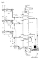
- the condensate outlet 5.2 of the steam treatment chamber 5 is via a condensate line 5.3 connected to a condensate tank 15 whose outlet can be closed by a controllable valve 16, the valve body 16.1 against the force of a spring 17 is adjustable.
- the condensate outlets 4.2 and 6.2 or 7.2 of the chambers 4 and 6 and the Cooling and drying chamber 7 are via lines 4.3, 6.3 and 7.3 to drain channels 18 and 19 and 20 of the condensate discharge device 23 connected, the each contain throttles 18.1 or 19.1 or 20.1.
- the upper mixing chamber 4 fed through the air inlet 4.1 compressed air serves to partition the steam treatment chamber 5, to largely prevent air from entering the steam treatment chamber 5 by moving into this mixing chamber 4 by suitable control of the inflowing into this chamber 4 Air sets a steam / air / mixed atmosphere.
- the cooling chamber 6 following the steam treatment chamber 5 also serves as the upper mixing chamber 4 for Abschotten the steam treatment chamber. 5 against the ingress of air from below.
- the Cooling air through the nozzle / shield plate system 13/14 as close as possible to the Thread is introduced, there is a rapid cooling of the thread to a to cause the highest possible heat-setting effect.
- moisture carried away by the thread is expelled from the thread, i.e. the thread is already dried to a certain extent.
- the above the system 13/14 located bell-shaped bottom 9 also performs "Stripping" from steam to a vapor deposition.
- the two chambers 4 or 6 thermally insulated from the Dampfbehanldungshunt 5. you will be therefore not or only slightly from the subsequent steam treatment chamber warmed up, so that even a small amount of heat energy this Chambers 4 and 6 leaves as energy loss.
- the thread passage between the steam treatment chamber 5 and the subsequent chamber 6 is relative long running, creating a mechanical partitioning of the steam treatment chamber 5 is effected.
- the cooling air is through the preferably made of thermally insulating material existing nozzle 13 directly across the free-running thread in the cooling chamber. 6 blown. This cooling air hits directly on the passing thread, which at low air flows to the largest possible cooling and also Drying effect leads. Due to the cooling air residual vapor particles between the Faserkapilaren of the thread largely expelled from the thread, so that the thread is dried.
- the cooling air flow must be selected appropriately the nozzle outlet are adjusted so that a swirling of the thread avoided becomes.
- the subsequent cooling and drying chamber 7, in the cooling air from the Chamber 6 enters through the connecting these two chambers thread channel causes another cooling and drying.
- the one of the thread still in this Cooling and drying chamber 7 entrained residual steam is in the range bell-shaped upwardly curved bottoms 10 expelled from the thread, wherein the residual condensate through the condensate outlet 7.2 and through the line 7.3 is drained.
- the cooling and drying chamber 7 is geometrically designed by means of ribs, that maximum thermal shielding occurs, i. this cooling chamber 7 is minimized by the residual steam entrained by the thread heated.
- the method is described as a theme fixing method in which the steam treatment chamber 5 saturated steam with a temperature of about 135 ° C by a Steam line 36 is supplied, which is connected to a steam central line 33 is, according to Figure 3 via individual connection lines 36a - 36x further treatment routes are connected.
- the chambers 4 and 6 are via individual connection lines 35 and 37 connected to central lines 32 and 34, respectively.
- To both central lines 32, 34 are single connection lines 35a - x or 37a - x connected.
- the compressed air lines 35 and 37 are 4.4 or 6.4 with shut-off valves equipped, the steam line 36 includes a shut-off valve 5.4.
- each monofilament F is essentially free of tension through the device described above.
- the "Control" block When the thread runs out, or if the thread breaks or a delivery system fails, the "Control" block also closes the valves 4.4, 5.4 and 6.4, which are connected to this block via control lines 4.6, 5.6 and 6.6.
- the steam treatment chamber 5 is heated to the required treatment temperature, the temperature being measured by means of the steam temperature sensors T D.
- the chambers 4 and 6 upstream and downstream of the chamber 5 are subjected to compressed air in such a way that, after a certain air-steam mixed atmosphere has been built up in these chambers 4 and 6, substantially no further vapor is released from the chamber 5 into these chambers can occur. It is essential that in the chambers 4 and 6 forming condensate is continuously discharged, as well as the forming in the chamber 5 condensate.
- the control of the respective air and vapor pressures is done centrally according to the following mode:
- the temperature sensor T D in the chamber 5 show the achievement of the desired treatment temperature -. B. about 135 ° as saturated steam temperature - on, which has been previously adjusted centrally on the control element (central controller) 22. This temperature is the reference variable and must be within a certain tolerance range.
- a comparison check is carried out by means of a temperature sensor T L in the steam line 36.
- the temperature sensor T K in the chamber 7 it is determined whether in this chamber due to physical effects certain temperature below the steam temperature T D prevails. If the temperature in the chamber 7 exceeds a certain tolerance range, for. B. of about 50 - 70 ° C, the air pressure in the chamber 7 must be increased centrally in small steps accordingly, whereby the cooling effect is stronger. The temperature T D must not rise.
- the corresponding air pressure in the cooling zone is lowered centrally and in a finely graduated manner so that the steam in the mixing zone receives a greater weight and the cooling air temperature in the chamber 7 increases slightly.
- the cooling air pressure in the air lines 35 and 37 and thus in the chambers. 4 and 6 must be controlled independently by means of the controller 21 a and 21 b be because the current through the chamber 5 thread the vapor medium with it rips and thus shifts the temperature zone in the direction of thread travel, which in the Chamber 6 leads to deviating from the chamber 4 temperatures.
Landscapes
- Engineering & Computer Science (AREA)
- Textile Engineering (AREA)
- Treatment Of Fiber Materials (AREA)
- Yarns And Mechanical Finishing Of Yarns Or Ropes (AREA)
Abstract
Description
- spannungsloses Führen des Fadens
- genaue Temperaturführung
- exakte Länge des Fadenweges durch die Dampf- oder Gasbehandlungszone;
- ausreichende und spontane Abkühlung des zum Zwecke der Thermofixierung mit Dampf behandelten Fadens, bevor der Faden wieder mechanisch belastet werden kann;
- gleichmäßige Einwirkung von Temperatur, Geschwindigkeit und Abkühlung aller Behandlungsstrecken einer Vielstellenmaschine;
- sichere und kostengünstige Ausführung des Systems;
- sauberes Anlaufen und Ausscheiden der einzelnen Behandlungsstrecke unter Berücksichtigung der Kondensatableitung bei einer Dampfbehandlung.
Die Temperaturfühler TD in der Kammer 5 zeigen das Erreichen der erwünschten Behandlungtemperatur - z. B. ca. 135° als Sattdampftemperatur - an, die zuvor am Regelorgan (Zentralregler) 22 zentral eingestellt worden ist. Diese Temperatur bildet die Führungsgröße und muss innerhalb eines bestimmten Toleranzbereiches liegen. Eine Vergleichskontrolle erfolgt mittels eines Temperaturfühlers TL in der Dampfleitung 36.
Claims (25)
- Vorrichtung zur Behandlung eines laufenden Fadens mit einem dampfförmigen Behandlungsmedium, enthaltend eine Säule von mehreren mit Fadeneinlauf- und Fadenauslaufkanälen versehenen, übereinander angeordneten Kammern, von denen eine eine mit einem Dampfeinlass und einem Kondensatauslass versehene Dampfbehandlungskammer (5) ist, der eine Mischkammer (4) vorgeschaltet und eine großvolumige Kühlkammer (6) nachgeschaltet sind, die beide jeweils einen Lufteinlass (4.1; 6,1) und einen Kondensatauslass (4.2; 6.2) aufweisen, wobei die Fadeneinlauf- und Fadenauslaufkanäle einen Öffnungsquerschnitt haben, der einerseits eine pneumatische Fadendurchfädelung ermöglicht und andererseits den Austausch von Luft und Dampf zwischen den Kammern so regelt, dass sich, gesteuert von einer die Dampf- und Lufteinspeisung in die Dampfbehandlungskammer (5) bzw. in die Mischkammern (4) und die Kühlkammer (6) regelnden Regeleinrichtung in den der Dampfbehandlungskammer (5) vor- und nachgeschalteten Kammern eine Dampf-Luft-Mischatmosphäre einstellt, die den Eintritt von Luft in die Dampfbehandlungskammer (5) weitgehend unterbindet, wobei der Lufteinlass (6.1) in die Kühlkammer (6) so gestaltet ist, dass der austretende Druckluftstrahl im wesentlichen unmittelbar auf den die Kühlkammer frei durchlaufenden Faden auftrifft.
- Vorrichtung nach Anspruch 1, dadurch gekennzeichnet, dass der Lufteinlass (6.1) eine in der Nähe des Fadenlaufweges endende, vorzugsweise aus thermisch isolierendem Material bestehende Düse (13) aufweist, an deren Düsenöffnung seitlich vom Fadenlaufweg liegende Abschirmplatten (14) anschließen.
- Vorrichtung nach Anspruch 1, dadurch gekennzeichnet, dass die Mischkammer (4) und die Kühlkammer (6) aus einem Material mit geringer Wärmeleitfähigkiet, vorzugsweise Keramikmaterial, bestehen.
- Vorrichtung nach Anspruch 1, dadurch gekennzeichnet, dass die Kühlkammer (6) einen Innendurchmesser im Bereich von 70 - 90 mm, vorzugsweise etwa 80 mm, hat.
- Vorrichtung nach Anspruch 4, dadurch gekennzeichnet, dass die Kühlkammer (6) eine Höhe im Bereich von 25 - 35 mm, vorzugsweise etwa 30 mm, hat.
- Vorrichtung nach Anspruch 1, dadurch gekennzeichnet, dass in der Kühlkammer (6) oberhalb der Düse (13) mindestens ein vorzugsweise glockenförmig nach oben gewölbter, bis zur Kammerinnenwand reichender Boden (9) angeordnet ist, der eine zentrisch angeordnete Fadenöffnung (9.1) und im Bereich seines unten liegenden, an die Kammerinnenwand angrenzenden Randes mindestens eine Kondensatabflussöffnung (9.2) aufweist.
- Vorrichtung nach Anspruch 1, dadurch gekennzeichnet, dass sich an die auf die Dampfbehandlungskammer (5) folgende Kühlkammer (6) eine einen Kondensatauslass (7.2) aufweisende Kühl- und Trockenkammer (7) anschließt, die mindestens einen vorzugsweise glockenförmig nach oben gewölbten, bis zur Kammerinnenwand reichenden Boden (10) aufweist, der eine zentrisch angeordnete Fadenöffnung und im Bereich seines unteren, an die Innenwand der Kühl- und Trokkenkammer (7) angrenzenden Randes mindestens eine Kondensatabflussöffnung (10.1) hat.
- Vorrichtung nach Anspruch 1, gekennzeichnet durch im Bereich ihrer oberen und unteren Enden Fadenlieferwerke (11, 12) angeordnet sind.
- Vorrichtung nach Anspruch 8, dadurch gekennzeichnet, dass ein Fadenlieferwerk (11) in einer der oberen Mischkammer (4) vorgeschalteten Vorkammer (3) angeordnet und das andere Lieferwerk (12) in einer auf die Kühl- und Trockenkammer (7) folgende Endkammer (8) angeordnet ist.
- Vorrichtung nach Anspruch 1, dadurch gekennzeichnet, dass der Kondensatauslass (5.2) der Dampfbehandlungskammer (5) verschließbar ist.
- Vorrichtung nach Anspruch 10, dadurch gekennzeichnet, dass der Kondensatauslass (5.2) der Dampfbehandlungskammer (5) über eine Kondensatleitung (5.3) an einen Kondensatbehälter (15) angeschlossen ist, dessen Auslass durch ein steuerbares Ventil (16) verschließbar ist.
- Vorrichtung nach Anspruch 11, dadurch gekennzeichnet, dass der Ventilkörper (16.1) des Ventils (16) gegen die Kraft einer Feder (17) verstellbar ist.
- Vorrichtung nach einem der vorherigen Ansprüche, dadurch gekennzeichnet, dass die Kondensatauslässe (4.2; 6.2; 7.2) der Misch- und Kühl-/Trockenkammern (4; 6; 7) über Leitungen (4.3; 6.3; 7.3) an Abflusskanäle (18; 19; 20) angeschlossen sind, die jeweils eine Drossel (18.1; 19.1; 20.1) enthalten.
- Vorrichtung nach einem derr Ansprüche 1 - 13, dadurch gekennzeichnet, dass die Böden der einen Kondensatauslass aufweisenden Kammern im Bereich der Fadenauslasskanäle mit einem diese Fadenauslasskanäle umgebenden Rückhaltewehr versehen sind.
- Vorrichtung nach Anspruch 9, dadurch gekennzeichnet, dass der Boden der Vorkammer (3) im Bereich des Fadenauslasskanals eine diesen Fadenauslasskanal umgebende Einbuchtung aufweist.
- Vorrichtung nach Anspruch 1, gekennzeichnet durch Absperrventile (4.4; 5.4; 6.4) in zu den Kammern (4 bzw. 5 bzw. 6) führenden Luft- und Dampfleitungen (35 bzw. 36 bzw. 37), welche Absperrventile von einem Block "Steuerung" in Abhängigkeit von in den Kammern (4, 5, 6) herrschenden Temperaturen geregelt werden.
- Verfahren zur Behandlung von laufenden Einzelfäden einer Vielstellenmaschine mit Dampf, bei dem man jeden Einzelfaden (F) im wesentlichen spannungsfrei eine Behandlungsstrecke, enthaltend eine mit Druckluft beaufschlagbare Mischkammer (4), eine daran anschließende mit Dampf beaufschlagbare Dampfbehandlungskammer (5) und eine daran anschließende mit Druckluft beaufschlagbare, relativ großvolumige, vorzugsweise aus thermisch isolierendem Material bestehende Kühlkammer (6) durchlaufen lässt, wobei man die Drucklufteinströmdrücke in die Mischkammer (4) und in die Kühlkammer (6) und den Dampfeinströmdruck in die Dampfbehandlungskammer (5) in Abhängigkeit von den Querschnitten und den Längen der diese Kammern und ggf. weitere Kammern miteinander verbindenden Fadenkanälen so regelt, dass ein Einströmen von Dampf in die Kammern (4, 6) nur in einem solchen Umfang stattfindet, dass sich in diesen Kammern (4, 6) eine die Dampfbehandlungskammer (5) gegen Einströmen von Luft abschottende Dampf-Luft-Mischatmosphäre ausbildet, wobei man das sich dabei in den Kammern (4, 6) bildende Kondensat gedrosselt kontinuierlich aus diesen Kammern ableitet und man die Betriebstemperatur in der Dampfbehandlungskammer (5) und die Temperaturen den an die Dampfbehandlungskammer angrenzenden Kammern (4, 6) misst, und diese Termperaturen als Regelgrößen für die Druckluft- und Dampfversorgung von Zentralreglern zuleitet.
- Verfahren nach Anspruch 17, dadurch gekennzeichnet, dass man den Faden zum Erzielen des erwünschten Behandlungszweckes eine ausreichend lange Dampfbehandlungskammer (5) frei durchlaufen lässt.
- Verfahren nach Anspruch 17 oder 18, dadurch gekennzeichnet, dass man den Faden hinter der an die Dampfbehandlungskammer (5) anschließenden Kühlkammer (6) eine Kühl- und Trockenkammer (7) durchlaufen lässt und das sich in dieser Kammer (7) bildende Kondensat gedrosselt kontinuierlich ableitet.
- Verfahren nach einem der Ansprüche 17 bis 19, dadurch gekennzeichnet, dass man die Dampfbehandlungskammer (5) und die dieser vorgeschalteten und nachgeschalteten Kammern (4, 6) einer einzelnen Fadenbehandlungsstrecke ausgehend von Zentralleitungen (32, 33, 34) und Zentralreglern (38, 39, 40) der Vielstellenmaschine über mit Absperrventilen (4.4; 5.4; 6.4) ausgerüstete Anschluss-Einzelleitungen (35, 36, 37) mit Druckluft bzw. Dampf versorgt.
- Verfahren nach Anspruch 17, dadurch gekennzeichnet, dass man während der Aufwärmphase der mit Dampf, z. B. Sattdampf von 135°C, beschickten Dampfbehandlungskammer (5) das sich in dieser Kammer bildende Kondensat ableitet und, nachdem die Dampfbehandlungskammer (5) ihre Betriebstemperatur erreicht hat, den Kondensatauslass (6.2) absperrt.
- Verfahren nach Anspruch 12, dadurch gekennzeichnet, dass man bei Unterschreiten oder Überschreiten vorgegebener Temperaturgrenzwerte in den mit Temperaturfühlern ausgerüsteten Kammern die jeweilige einzelne Fadenbehandlungsstrecke absperrt und den Fadendurchlauf durch die Fadenbehandlungsstrecke unterbricht.
- Verfahren nach Anspruch 22, dadurch gekennzeichnet, dass man die Betriebstemperatur in der Dampfbehandlungskammer (5) und die Temperaturen in der der Dampfbehandlungskammer vorgeschalteten Kammer (3) und in der Kühlkammer (7) misst, und diese Temperaturen als Regelgörßen für die Druckluft- und Dampfversorgung den Zentralregelorganen (21a; 21b; 22) zuleitet.
- Verfahren nach Anspruch 23, dadurch gekennzeichnet, dass man bei Unterschreiten oder Überschreiten vorgegebener Temperaturgrenzwerte in den mit Temperaturfühlern ausgerüsteten Kammern die jeweilige einzelne Fadenbehandlungsstrecke absperrt und den Fadendurchlauf durch die Fadenbehandlungsstrecke unterbricht.
- Vorrichtung nach Anspruch 7, dadurch gekennzeichnet, dass mindestens vier, vorzugsweise bis zu acht oder mehr Böden (10) vorgesehen sind.
Applications Claiming Priority (2)
| Application Number | Priority Date | Filing Date | Title |
|---|---|---|---|
| DE10348277 | 2003-10-17 | ||
| DE10348277 | 2003-10-17 |
Publications (3)
| Publication Number | Publication Date |
|---|---|
| EP1528134A2 true EP1528134A2 (de) | 2005-05-04 |
| EP1528134A3 EP1528134A3 (de) | 2006-01-11 |
| EP1528134B1 EP1528134B1 (de) | 2011-11-09 |
Family
ID=34399534
Family Applications (1)
| Application Number | Title | Priority Date | Filing Date |
|---|---|---|---|
| EP04022253A Expired - Lifetime EP1528134B1 (de) | 2003-10-17 | 2004-09-17 | Vorrichtung zur Behandlung eines laufenden Fadens mit einem dampfförmigen Behandlungsmedium |
Country Status (5)
| Country | Link |
|---|---|
| US (1) | US7356984B2 (de) |
| EP (1) | EP1528134B1 (de) |
| JP (1) | JP4718156B2 (de) |
| CN (1) | CN100343436C (de) |
| AT (1) | ATE532893T1 (de) |
Cited By (4)
| Publication number | Priority date | Publication date | Assignee | Title |
|---|---|---|---|---|
| DE102006040063A1 (de) * | 2006-08-26 | 2008-02-28 | Oerlikon Textile Gmbh & Co. Kg | Zwirnmaschine |
| DE102007014556A1 (de) | 2007-03-27 | 2008-10-02 | Resch Maschinenbau Gmbh | Kombination eines Verfahrens zum Erzeugen von Frieze-Garn mit einer Kablier- oder Zwirnmaschine bzw. Integration dieses Verfahrens in eine Kablier- oder Zwirnmaschine verbunden mit einer Heat-Set-Einheit |
| DE102007038375B3 (de) * | 2007-08-14 | 2009-01-15 | Power-Heat-Set Gmbh | Heatsetting-Behälter |
| EP2549002A1 (de) * | 2011-07-20 | 2013-01-23 | Oerlikon Textile GmbH & Co. KG | Garnbehandlungskammer |
Families Citing this family (11)
| Publication number | Priority date | Publication date | Assignee | Title |
|---|---|---|---|---|
| DE102010022211A1 (de) * | 2010-05-20 | 2011-11-24 | Oerlikon Textile Gmbh & Co. Kg | Garnschleuse zur Abdichtung einer unter Überdruck stehenden Garnbehandlungskammer |
| CN101954357B (zh) * | 2010-09-26 | 2012-07-04 | 新昌县艺力机械有限公司 | 连续式散纤清洗机 |
| MX2013009249A (es) * | 2011-02-10 | 2013-11-04 | Mitsubishi Rayon Co | Un aparato de tratamiento por vapor a presion de un haz de fibras acrilicas precursoras de fibras de carbono y un metodo para producir un haz de fibras acrilicas. |
| EP2684989B1 (de) * | 2011-03-09 | 2019-06-26 | Mitsubishi Chemical Corporation | Vorrichtung zur druckdampfbehandlung von faserbündel und herstellungsverfahren für faserbündel von kohlenfaser |
| CN103764891B (zh) * | 2011-08-22 | 2015-05-13 | 三菱丽阳株式会社 | 蒸汽拉伸装置 |
| US9422645B2 (en) * | 2011-09-09 | 2016-08-23 | Oerlikon Textile Gmbh & Co. Kg | Device for treating a thread |
| CN102619040B (zh) * | 2012-02-16 | 2014-06-11 | 机械科学研究总院先进制造技术研究中心 | 纱线调湿机及其调湿方法 |
| CN104233556A (zh) * | 2013-06-08 | 2014-12-24 | 苏州联优织造有限公司 | 纺线的冷却装置 |
| CN108588921A (zh) * | 2018-07-23 | 2018-09-28 | 张家港市金星纺织有限公司 | 一种氨纶纺纱机用加热辊体 |
| KR102011057B1 (ko) * | 2018-10-02 | 2019-08-20 | 장원동 | 발열사 제조장치 |
| KR102359627B1 (ko) * | 2020-09-02 | 2022-03-10 | 고원니트(주) | 첨가제 처리가 가능한 원사의 단선 감지장치 |
Family Cites Families (15)
| Publication number | Priority date | Publication date | Assignee | Title |
|---|---|---|---|---|
| US2398856A (en) * | 1942-07-29 | 1946-04-23 | Celanese Corp | Apparatus for the treatment of artificial materials |
| US3742695A (en) * | 1969-06-25 | 1973-07-03 | R Conrad | Thermoplastic yarn plasticizing device and method of plasticizing thermoplastic yarn |
| US3837186A (en) * | 1970-01-21 | 1974-09-24 | Omnium De Prospective Ind Sa | Apparatus for the continuous treatment of threads |
| FR2098482A5 (de) * | 1970-01-21 | 1972-03-10 | Omnium De Prospective Ind Sa | |
| US3783596A (en) * | 1971-05-26 | 1974-01-08 | Du Pont | Jet application of textile finish to moving threadlines |
| DE2130759C2 (de) * | 1971-06-22 | 1982-12-30 | Hacoba Textilmaschinen Gmbh & Co Kg, 5600 Wuppertal | Vorrichtung zum kontinuierlichen Behandeln, insbesondere Schrumpfen von textilem Faden- oder Garnmaterial |
| NL150527B (nl) * | 1974-08-21 | 1976-08-16 | Hollandse Signaalapparaten Bv | Valstwistorgaan alsmede de werkwijze voor het vervaardigen van twistloos of nagenoeg twistloos garen en voor het aanbrengen van kleurstoffen in getwist garen met behulp van dit valstwistorgaan. |
| US3940955A (en) * | 1974-11-26 | 1976-03-02 | E. I. Du Pont De Nemours And Co. | Yarn extraction and washing apparatus |
| GB1592646A (en) * | 1976-12-01 | 1981-07-08 | Ici Ltd | Yarn treatment |
| DE3634557A1 (de) * | 1986-10-10 | 1988-04-14 | Fritz Stahlecker | Vorrichtung zum pneumatischen falschdrallspinnen |
| DE59107941D1 (de) * | 1990-05-18 | 1996-07-25 | Rieter Ag Maschf | Verfahren und Vorrichtung zum Entfernen von Flüssigkeit von schnellaufenden Fäden |
| US5287606A (en) * | 1992-03-10 | 1994-02-22 | Soft Blast, Inc. | Apparatus for treating traveling textile material in a pressurized fluid |
| FR2754279B1 (fr) * | 1996-10-09 | 1998-12-04 | Jean Michel Alavoine | Procede de teinture a la continue de fils et files de fibres |
| US6168743B1 (en) * | 1999-06-15 | 2001-01-02 | Arteva North America S.A.R.L. | Method of continuously heat treating articles and apparatus therefor |
| EP1348785A1 (de) * | 2002-03-28 | 2003-10-01 | Power- heat-set GmbH | Vorrichtung zum Behandeln von langgestrecktem Gut, insbesondere von fadenartigen Textilgarnen |
-
2004
- 2004-09-17 EP EP04022253A patent/EP1528134B1/de not_active Expired - Lifetime
- 2004-09-17 AT AT04022253T patent/ATE532893T1/de active
- 2004-10-14 CN CNB2004100837332A patent/CN100343436C/zh not_active Expired - Fee Related
- 2004-10-15 US US10/966,498 patent/US7356984B2/en active Active
- 2004-10-18 JP JP2004303322A patent/JP4718156B2/ja not_active Expired - Fee Related
Cited By (5)
| Publication number | Priority date | Publication date | Assignee | Title |
|---|---|---|---|---|
| DE102006040063A1 (de) * | 2006-08-26 | 2008-02-28 | Oerlikon Textile Gmbh & Co. Kg | Zwirnmaschine |
| WO2008025390A1 (de) * | 2006-08-26 | 2008-03-06 | Oerlikon Textile Gmbh & Co. Kg | Zwirnmaschine |
| DE102007014556A1 (de) | 2007-03-27 | 2008-10-02 | Resch Maschinenbau Gmbh | Kombination eines Verfahrens zum Erzeugen von Frieze-Garn mit einer Kablier- oder Zwirnmaschine bzw. Integration dieses Verfahrens in eine Kablier- oder Zwirnmaschine verbunden mit einer Heat-Set-Einheit |
| DE102007038375B3 (de) * | 2007-08-14 | 2009-01-15 | Power-Heat-Set Gmbh | Heatsetting-Behälter |
| EP2549002A1 (de) * | 2011-07-20 | 2013-01-23 | Oerlikon Textile GmbH & Co. KG | Garnbehandlungskammer |
Also Published As
| Publication number | Publication date |
|---|---|
| CN100343436C (zh) | 2007-10-17 |
| US7356984B2 (en) | 2008-04-15 |
| JP4718156B2 (ja) | 2011-07-06 |
| ATE532893T1 (de) | 2011-11-15 |
| HK1074656A1 (en) | 2005-11-18 |
| CN1609320A (zh) | 2005-04-27 |
| EP1528134B1 (de) | 2011-11-09 |
| EP1528134A3 (de) | 2006-01-11 |
| JP2005120569A (ja) | 2005-05-12 |
| US20050081335A1 (en) | 2005-04-21 |
Similar Documents
| Publication | Publication Date | Title |
|---|---|---|
| EP1528134A2 (de) | Vorrichtung und Verfahren zur Behandlung eines laufenden Fadens mit einem dampfförmigen Behandlungsmedium | |
| DE1435653C2 (de) | Vorrichtung zum kontinuierlichen Kräuseln thermoplastischer Fäden | |
| DE4301023C2 (de) | Verfahren und Vorrichtung zum Erhöhen von Glanz und/oder Glätte einer Papierbahn | |
| DE2706162C2 (de) | Anlage zur fortlaufenden Wärmebehandlung eines eine Kammer durchlaufenden Behandlungsgutes | |
| DE2733745A1 (de) | Verfahren zum kondensieren von daempfen einer fluechtigen fluessigkeit | |
| EP0418649B1 (de) | Verfahren und Vorrichtung zum Nassveredeln von Textilgut | |
| EP3158117B1 (de) | Oxidationsofen | |
| EP0528160B1 (de) | Dampfblaskasten | |
| EP3300486A1 (de) | Verfahren und vorrichtung zum kühlen von extrudierten profilen | |
| DE69013271T2 (de) | In Zonen geteilter zylindrischer Trockner. | |
| DE1792139A1 (de) | Mehrstufen-Entspannungsverdampfer fuer die Destillation von Seewasser od.dgl. | |
| EP1348785A1 (de) | Vorrichtung zum Behandeln von langgestrecktem Gut, insbesondere von fadenartigen Textilgarnen | |
| DE3701407C1 (de) | Dampfblaskasten | |
| EP3271133B1 (de) | Behandlungsfluidführung in einer folienreckanlage | |
| CH646775A5 (en) | Air cooler | |
| CH663222A5 (de) | Spinnanlage fuer chemiefasern. | |
| EP0950499B1 (de) | Verfahren zur Herstellung von oberflächenreinen Blasfolien sowie Einrichtung zur Durchführung des Verfahrens | |
| WO2002006575A1 (de) | Verfahren und vorrichtung zur kontinuierlichen behandlung von synthetischen fäden in einer wärmeaustauschkammer | |
| EP1528342B1 (de) | Verfahren zur Trocknung von Gut und Vorrichtung zur Durchführung des Verfahrens | |
| DE947330C (de) | Vorrichtung zum Trockenspinnen Kuenstlicher Faeden | |
| DE3742982C2 (de) | ||
| DE3906969A1 (de) | Verfahren zur regelung der raumatmosphaere einer dampfbadekabine | |
| EP0324941B1 (de) | Verfahren und Vorrichtung zum Behandeln von Textilgut | |
| DE641090C (de) | Verfahren und Vorrichtung zum Trocknen von Textilgut | |
| DE1954097A1 (de) | Verfahren und Vorrichtung zum Kuehlen oder Erwaermen von in Portionsgefaessen befindlichen Nahrungsmitteln |
Legal Events
| Date | Code | Title | Description |
|---|---|---|---|
| PUAI | Public reference made under article 153(3) epc to a published international application that has entered the european phase |
Free format text: ORIGINAL CODE: 0009012 |
|
| AK | Designated contracting states |
Kind code of ref document: A2 Designated state(s): AT BE BG CH CY CZ DE DK EE ES FI FR GB GR HU IE IT LI LU MC NL PL PT RO SE SI SK TR |
|
| AX | Request for extension of the european patent |
Extension state: AL HR LT LV MK |
|
| PUAL | Search report despatched |
Free format text: ORIGINAL CODE: 0009013 |
|
| AK | Designated contracting states |
Kind code of ref document: A3 Designated state(s): AT BE BG CH CY CZ DE DK EE ES FI FR GB GR HU IE IT LI LU MC NL PL PT RO SE SI SK TR |
|
| AX | Request for extension of the european patent |
Extension state: AL HR LT LV MK |
|
| 17P | Request for examination filed |
Effective date: 20060704 |
|
| AKX | Designation fees paid |
Designated state(s): AT BE BG CH CY CZ DE DK EE ES FI FR GB GR HU IE IT LI LU MC NL PL PT RO SE SI SK TR |
|
| RAP1 | Party data changed (applicant data changed or rights of an application transferred) |
Owner name: OERLIKON TEXTILE GMBH & CO. KG |
|
| 17Q | First examination report despatched |
Effective date: 20080403 |
|
| RAP1 | Party data changed (applicant data changed or rights of an application transferred) |
Owner name: OERLIKON TEXTILE GMBH & CO. KG |
|
| RTI1 | Title (correction) |
Free format text: DEVICE FOR TREATING A RUNNING THREAD WITH A VAPOUR |
|
| GRAP | Despatch of communication of intention to grant a patent |
Free format text: ORIGINAL CODE: EPIDOSNIGR1 |
|
| GRAS | Grant fee paid |
Free format text: ORIGINAL CODE: EPIDOSNIGR3 |
|
| GRAA | (expected) grant |
Free format text: ORIGINAL CODE: 0009210 |
|
| AK | Designated contracting states |
Kind code of ref document: B1 Designated state(s): AT BE BG CH CY CZ DE DK EE ES FI FR GB GR HU IE IT LI LU MC NL PL PT RO SE SI SK TR |
|
| REG | Reference to a national code |
Ref country code: GB Ref legal event code: FG4D Free format text: NOT ENGLISH |
|
| REG | Reference to a national code |
Ref country code: CH Ref legal event code: EP |
|
| REG | Reference to a national code |
Ref country code: IE Ref legal event code: FG4D Free format text: LANGUAGE OF EP DOCUMENT: GERMAN |
|
| REG | Reference to a national code |
Ref country code: DE Ref legal event code: R096 Ref document number: 502004013040 Country of ref document: DE Effective date: 20111229 |
|
| REG | Reference to a national code |
Ref country code: NL Ref legal event code: VDEP Effective date: 20111109 |
|
| PG25 | Lapsed in a contracting state [announced via postgrant information from national office to epo] |
Ref country code: SE Free format text: LAPSE BECAUSE OF FAILURE TO SUBMIT A TRANSLATION OF THE DESCRIPTION OR TO PAY THE FEE WITHIN THE PRESCRIBED TIME-LIMIT Effective date: 20111109 Ref country code: PT Free format text: LAPSE BECAUSE OF FAILURE TO SUBMIT A TRANSLATION OF THE DESCRIPTION OR TO PAY THE FEE WITHIN THE PRESCRIBED TIME-LIMIT Effective date: 20120309 Ref country code: GR Free format text: LAPSE BECAUSE OF FAILURE TO SUBMIT A TRANSLATION OF THE DESCRIPTION OR TO PAY THE FEE WITHIN THE PRESCRIBED TIME-LIMIT Effective date: 20120210 Ref country code: NL Free format text: LAPSE BECAUSE OF FAILURE TO SUBMIT A TRANSLATION OF THE DESCRIPTION OR TO PAY THE FEE WITHIN THE PRESCRIBED TIME-LIMIT Effective date: 20111109 Ref country code: PL Free format text: LAPSE BECAUSE OF FAILURE TO SUBMIT A TRANSLATION OF THE DESCRIPTION OR TO PAY THE FEE WITHIN THE PRESCRIBED TIME-LIMIT Effective date: 20111109 Ref country code: SI Free format text: LAPSE BECAUSE OF FAILURE TO SUBMIT A TRANSLATION OF THE DESCRIPTION OR TO PAY THE FEE WITHIN THE PRESCRIBED TIME-LIMIT Effective date: 20111109 |
|
| REG | Reference to a national code |
Ref country code: IE Ref legal event code: FD4D |
|
| PG25 | Lapsed in a contracting state [announced via postgrant information from national office to epo] |
Ref country code: CY Free format text: LAPSE BECAUSE OF FAILURE TO SUBMIT A TRANSLATION OF THE DESCRIPTION OR TO PAY THE FEE WITHIN THE PRESCRIBED TIME-LIMIT Effective date: 20111109 |
|
| PG25 | Lapsed in a contracting state [announced via postgrant information from national office to epo] |
Ref country code: BG Free format text: LAPSE BECAUSE OF FAILURE TO SUBMIT A TRANSLATION OF THE DESCRIPTION OR TO PAY THE FEE WITHIN THE PRESCRIBED TIME-LIMIT Effective date: 20120209 Ref country code: SK Free format text: LAPSE BECAUSE OF FAILURE TO SUBMIT A TRANSLATION OF THE DESCRIPTION OR TO PAY THE FEE WITHIN THE PRESCRIBED TIME-LIMIT Effective date: 20111109 Ref country code: EE Free format text: LAPSE BECAUSE OF FAILURE TO SUBMIT A TRANSLATION OF THE DESCRIPTION OR TO PAY THE FEE WITHIN THE PRESCRIBED TIME-LIMIT Effective date: 20111109 Ref country code: CZ Free format text: LAPSE BECAUSE OF FAILURE TO SUBMIT A TRANSLATION OF THE DESCRIPTION OR TO PAY THE FEE WITHIN THE PRESCRIBED TIME-LIMIT Effective date: 20111109 Ref country code: IE Free format text: LAPSE BECAUSE OF FAILURE TO SUBMIT A TRANSLATION OF THE DESCRIPTION OR TO PAY THE FEE WITHIN THE PRESCRIBED TIME-LIMIT Effective date: 20111109 Ref country code: DK Free format text: LAPSE BECAUSE OF FAILURE TO SUBMIT A TRANSLATION OF THE DESCRIPTION OR TO PAY THE FEE WITHIN THE PRESCRIBED TIME-LIMIT Effective date: 20111109 |
|
| PG25 | Lapsed in a contracting state [announced via postgrant information from national office to epo] |
Ref country code: RO Free format text: LAPSE BECAUSE OF FAILURE TO SUBMIT A TRANSLATION OF THE DESCRIPTION OR TO PAY THE FEE WITHIN THE PRESCRIBED TIME-LIMIT Effective date: 20111109 |
|
| PLBE | No opposition filed within time limit |
Free format text: ORIGINAL CODE: 0009261 |
|
| STAA | Information on the status of an ep patent application or granted ep patent |
Free format text: STATUS: NO OPPOSITION FILED WITHIN TIME LIMIT |
|
| 26N | No opposition filed |
Effective date: 20120810 |
|
| REG | Reference to a national code |
Ref country code: DE Ref legal event code: R097 Ref document number: 502004013040 Country of ref document: DE Effective date: 20120810 |
|
| BERE | Be: lapsed |
Owner name: OERLIKON TEXTILE G.M.B.H. & CO. KG Effective date: 20120930 |
|
| PG25 | Lapsed in a contracting state [announced via postgrant information from national office to epo] |
Ref country code: ES Free format text: LAPSE BECAUSE OF FAILURE TO SUBMIT A TRANSLATION OF THE DESCRIPTION OR TO PAY THE FEE WITHIN THE PRESCRIBED TIME-LIMIT Effective date: 20120220 Ref country code: MC Free format text: LAPSE BECAUSE OF NON-PAYMENT OF DUE FEES Effective date: 20120930 |
|
| PG25 | Lapsed in a contracting state [announced via postgrant information from national office to epo] |
Ref country code: FI Free format text: LAPSE BECAUSE OF FAILURE TO SUBMIT A TRANSLATION OF THE DESCRIPTION OR TO PAY THE FEE WITHIN THE PRESCRIBED TIME-LIMIT Effective date: 20111109 |
|
| PG25 | Lapsed in a contracting state [announced via postgrant information from national office to epo] |
Ref country code: BE Free format text: LAPSE BECAUSE OF NON-PAYMENT OF DUE FEES Effective date: 20120930 |
|
| REG | Reference to a national code |
Ref country code: CH Ref legal event code: PUE Owner name: SAURER GERMANY GMBH AND CO. KG, DE Free format text: FORMER OWNER: OERLIKON TEXTILE GMBH AND CO. KG, DE Ref country code: CH Ref legal event code: NV Representative=s name: SCHMAUDER AND PARTNER AG PATENT- UND MARKENANW, CH |
|
| REG | Reference to a national code |
Ref country code: DE Ref legal event code: R081 Ref document number: 502004013040 Country of ref document: DE Owner name: SAURER GERMANY GMBH & CO. KG, DE Free format text: FORMER OWNER: SAURER GMBH & CO. KG, 41069 MOENCHENGLADBACH, DE Effective date: 20111110 Ref country code: DE Ref legal event code: R081 Ref document number: 502004013040 Country of ref document: DE Owner name: SAURER GERMANY GMBH & CO. KG, DE Free format text: FORMER OWNER: OERLIKON TEXTILE GMBH & CO. KG, 42897 REMSCHEID, DE Effective date: 20130918 |
|
| REG | Reference to a national code |
Ref country code: AT Ref legal event code: MM01 Ref document number: 532893 Country of ref document: AT Kind code of ref document: T Effective date: 20120917 |
|
| REG | Reference to a national code |
Ref country code: GB Ref legal event code: 732E Free format text: REGISTERED BETWEEN 20131121 AND 20131127 |
|
| PG25 | Lapsed in a contracting state [announced via postgrant information from national office to epo] |
Ref country code: AT Free format text: LAPSE BECAUSE OF NON-PAYMENT OF DUE FEES Effective date: 20120917 |
|
| REG | Reference to a national code |
Ref country code: FR Ref legal event code: TP Owner name: SAURER GERMANY GMBH & CO. KG, DE Effective date: 20140107 |
|
| PG25 | Lapsed in a contracting state [announced via postgrant information from national office to epo] |
Ref country code: LU Free format text: LAPSE BECAUSE OF NON-PAYMENT OF DUE FEES Effective date: 20120917 |
|
| REG | Reference to a national code |
Ref country code: CH Ref legal event code: PCOW Free format text: NEW ADDRESS: LEVERKUSER STRASSE 65, 42897 REMSCHEID (DE) |
|
| PG25 | Lapsed in a contracting state [announced via postgrant information from national office to epo] |
Ref country code: HU Free format text: LAPSE BECAUSE OF FAILURE TO SUBMIT A TRANSLATION OF THE DESCRIPTION OR TO PAY THE FEE WITHIN THE PRESCRIBED TIME-LIMIT Effective date: 20040917 |
|
| REG | Reference to a national code |
Ref country code: FR Ref legal event code: PLFP Year of fee payment: 12 |
|
| PGFP | Annual fee paid to national office [announced via postgrant information from national office to epo] |
Ref country code: GB Payment date: 20150924 Year of fee payment: 12 |
|
| PGFP | Annual fee paid to national office [announced via postgrant information from national office to epo] |
Ref country code: FR Payment date: 20150924 Year of fee payment: 12 |
|
| PGFP | Annual fee paid to national office [announced via postgrant information from national office to epo] |
Ref country code: IT Payment date: 20150930 Year of fee payment: 12 |
|
| PGFP | Annual fee paid to national office [announced via postgrant information from national office to epo] |
Ref country code: CH Payment date: 20160926 Year of fee payment: 13 |
|
| PGFP | Annual fee paid to national office [announced via postgrant information from national office to epo] |
Ref country code: TR Payment date: 20160907 Year of fee payment: 13 |
|
| PGFP | Annual fee paid to national office [announced via postgrant information from national office to epo] |
Ref country code: DE Payment date: 20160930 Year of fee payment: 13 |
|
| GBPC | Gb: european patent ceased through non-payment of renewal fee |
Effective date: 20160917 |
|
| REG | Reference to a national code |
Ref country code: FR Ref legal event code: ST Effective date: 20170531 |
|
| PG25 | Lapsed in a contracting state [announced via postgrant information from national office to epo] |
Ref country code: FR Free format text: LAPSE BECAUSE OF NON-PAYMENT OF DUE FEES Effective date: 20160930 Ref country code: GB Free format text: LAPSE BECAUSE OF NON-PAYMENT OF DUE FEES Effective date: 20160917 |
|
| PG25 | Lapsed in a contracting state [announced via postgrant information from national office to epo] |
Ref country code: IT Free format text: LAPSE BECAUSE OF NON-PAYMENT OF DUE FEES Effective date: 20160917 |
|
| REG | Reference to a national code |
Ref country code: DE Ref legal event code: R119 Ref document number: 502004013040 Country of ref document: DE |
|
| REG | Reference to a national code |
Ref country code: CH Ref legal event code: PL |
|
| PG25 | Lapsed in a contracting state [announced via postgrant information from national office to epo] |
Ref country code: DE Free format text: LAPSE BECAUSE OF NON-PAYMENT OF DUE FEES Effective date: 20180404 Ref country code: CH Free format text: LAPSE BECAUSE OF NON-PAYMENT OF DUE FEES Effective date: 20170930 Ref country code: LI Free format text: LAPSE BECAUSE OF NON-PAYMENT OF DUE FEES Effective date: 20170930 |
|
| PG25 | Lapsed in a contracting state [announced via postgrant information from national office to epo] |
Ref country code: TR Free format text: LAPSE BECAUSE OF NON-PAYMENT OF DUE FEES Effective date: 20170917 |