EP1528129A2 - Method and device for treating an advancing yarn with a gaseous or vaporous medium - Google Patents
Method and device for treating an advancing yarn with a gaseous or vaporous medium Download PDFInfo
- Publication number
- EP1528129A2 EP1528129A2 EP04018188A EP04018188A EP1528129A2 EP 1528129 A2 EP1528129 A2 EP 1528129A2 EP 04018188 A EP04018188 A EP 04018188A EP 04018188 A EP04018188 A EP 04018188A EP 1528129 A2 EP1528129 A2 EP 1528129A2
- Authority
- EP
- European Patent Office
- Prior art keywords
- thread
- thread guide
- yarn
- guide element
- guide elements
- Prior art date
- Legal status (The legal status is an assumption and is not a legal conclusion. Google has not performed a legal analysis and makes no representation as to the accuracy of the status listed.)
- Granted
Links
Images


Classifications
-
- D—TEXTILES; PAPER
- D06—TREATMENT OF TEXTILES OR THE LIKE; LAUNDERING; FLEXIBLE MATERIALS NOT OTHERWISE PROVIDED FOR
- D06B—TREATING TEXTILE MATERIALS USING LIQUIDS, GASES OR VAPOURS
- D06B23/00—Component parts, details, or accessories of apparatus or machines, specially adapted for the treating of textile materials, not restricted to a particular kind of apparatus, provided for in groups D06B1/00 - D06B21/00
- D06B23/14—Containers, e.g. vats
- D06B23/18—Sealing arrangements
-
- D—TEXTILES; PAPER
- D06—TREATMENT OF TEXTILES OR THE LIKE; LAUNDERING; FLEXIBLE MATERIALS NOT OTHERWISE PROVIDED FOR
- D06B—TREATING TEXTILE MATERIALS USING LIQUIDS, GASES OR VAPOURS
- D06B23/00—Component parts, details, or accessories of apparatus or machines, specially adapted for the treating of textile materials, not restricted to a particular kind of apparatus, provided for in groups D06B1/00 - D06B21/00
- D06B23/14—Containers, e.g. vats
- D06B23/16—Containers, e.g. vats with means for introducing or removing textile materials without modifying container pressure
-
- D—TEXTILES; PAPER
- D06—TREATMENT OF TEXTILES OR THE LIKE; LAUNDERING; FLEXIBLE MATERIALS NOT OTHERWISE PROVIDED FOR
- D06B—TREATING TEXTILE MATERIALS USING LIQUIDS, GASES OR VAPOURS
- D06B3/00—Passing of textile materials through liquids, gases or vapours to effect treatment, e.g. washing, dyeing, bleaching, sizing, impregnating
- D06B3/04—Passing of textile materials through liquids, gases or vapours to effect treatment, e.g. washing, dyeing, bleaching, sizing, impregnating of yarns, threads or filaments
- D06B3/045—Passing of textile materials through liquids, gases or vapours to effect treatment, e.g. washing, dyeing, bleaching, sizing, impregnating of yarns, threads or filaments in a tube or a groove
Definitions
- the invention relates to a method and a device for treating a thread with a gaseous or vaporous medium.
- the invention has for its object to provide a method and an apparatus create, with which it is possible a running thread with a under pressure stationary, gaseous or vaporous medium to be treated, since at overpressure bring the medium closer to the single capillary over the cross section of the thread leaves, especially if the thread tension is low.
- a thread treatment chamber passed through by a thread which has a pressure chamber portion in the under pressure stationary treatment medium is injected, inlet side and outlet side Forward or downstream "thread locks", in which the current thread itself Function of a sealing element has to prevent inadvertent leakage of the Pressured treatment medium from the yarn treatment chamber so far as possible to prevent.
- the single yarn sluice must be designed that they of thread thickening, for example Knotstellen or the like, go through may be, and still the possibility of a preferably pneumatic thread threading should be given.
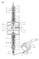
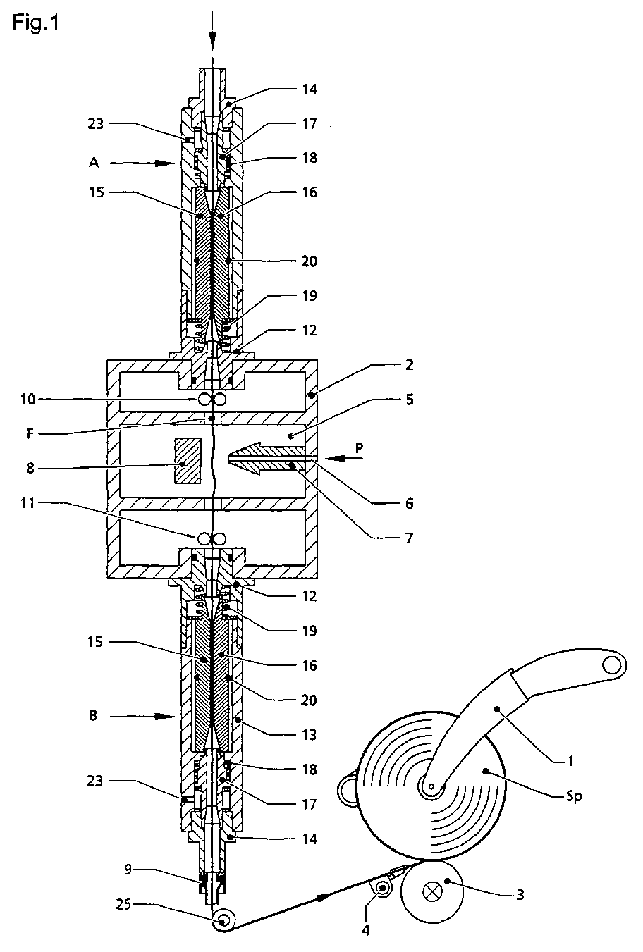
- Figure 1 shows a schematic representation of a side view of a not to the invention belonging Aufwickelaggregats, consisting of a bobbin frame. 1 for supporting a bobbin tube or spool Sp, a spool driving Sp friction drive roller and a traversing yarn guide 4.
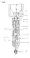
- the device according to the invention contains as part of a thread treatment chamber x a pressure chamber section 5 with a connection 6 for blowing an under Pressurized, gaseous or vaporous treatment medium through a nozzle 7, whose outflow opening 8 may be opposed by a baffle 8.
- the thread treatment chamber 2 is diametrically opposite inlet and outlet openings provided in the sealing threadlockers A and B are used, which are essentially identical with each other, except that the lower yarn lock B a Druckbuchinjektor 9 for threading a thread assigned by the yarn locks A and B and the yarn treatment chamber 2 is.
- two are shown schematically Yarn supply units 10 and 11 arranged to the thread F substantially free of tension through the filament treatment chamber 2 and the pressure chamber section 5 to promote.
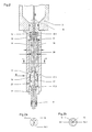
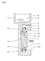
- the connecting piece 12 is in the illustrated in Figure 2 lower yarn lock B provided with a downwardly projecting centering and expanding cone 12.1.
- the piston 17 is at its top with an upwardly projecting centering or expanding cone 17.1 provided.
- the two thread guide elements 15 and 16 are at their upper and lower ends configured to be substantially one together Construct tapered inlet or outlet opening into which the centering or Spreader cone 12.1 or 17.1 protrude or due to the resilient support on the one hand the thread guide elements 15, 16 and on the other hand of the piston 17 are retractable.
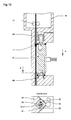
- FIG. 3 differs from the embodiment according to Figure 2, characterized in that instead of an annular spring 20, opposing magnets 22 are provided to the two yarn guide elements against each other to press.
- the by the two preferably ground thread guide elements 15, 16th formed thread channel has a Faden barnlklaquerrough, which is essentially the Titer or the cross section of the textile thread to be processed corresponds.
- Faden essentially the Titer or the cross section of the textile thread to be processed corresponds.
- the overpressure of the still with the thread through the Thread channel flowing treatment medium, the two thread guide elements 15, 16 do not press apart, as the effective pressure area is very low is substantially limited to thread diameter times the length of the yarn passage. This pressure affects the two guide elements 15,16 cohesive Ring spring against.
- a ring spring can also be an O-ring or it could magnets 22 ( Figure 3) may be provided.
- the continuous thread is centered between the two guide elements, since he seeks the path of the least frictional resistance. As a result, no Faserkapillare between the thread guide elements 15, 16 is clamped.
- the two thread guide elements are on passing thread over the two centered lower and upper centering or expanding cone 12.1 and 17.1, and indeed in cooperation with the conical inlet and outlet openings at the top and lower ends of the thread guide elements.
- a thread passing through the thread lock B opens Knot (thread thickening) the thread channel between the two thread guide elements, against the force of the annular spring 20 (or the magnets 22) to the outside be pressed. The occurring, small lateral pressure medium losses in the knot run are negligible. After passing through the knot through the "thread lock" the thread channel is closed again.
- the two thread guide elements 15, 16 of the lower yarn lock B are with their lower ends supported on an annular shoulder of the housing 13.
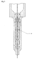
- the individual Threadlock a first thread guide element 51 in the form of a multi-edge strip, preferably square bar, on whose longitudinal edges in different Distances to the groin axis are flattened.
- the second thread guide element consists of two angularly arranged support surfaces 52.1; 52.2, against which the outer surfaces located between the flattened edges the square bar 51 by means of an example acting on a lever 55 Spring 54 are pressed.
- the two support surfaces 52.1; 52.2 are part of a support block 52, in addition lower and upper seats 52.3; 52.4, between which the square bar 51 in the operating position shown in FIG. 9 by means of sealing rings 60, 61 is supported.
- the square bar is at its lower end with one to its axle center eccentric blind bore 51.1 and at its top with one to the bore 51.1 axially aligned blind bore 51.2 provided.
- the holes 51.1 or 51.2 lie opposite coaxially aligned support pins 62 and 63, their projecting into the bores 51.1 and 51.2 ends substantially the Have the shape of a cone.
- the axes of the pins 62, 63 are eccentric to the Axes of the two blind holes 51.1, 51.2.
- One on the bottom of the square bar 51 acting compression spring 64 pushes the square bar 51 in the in the Figures 9 and 10 illustrated operating positions against the upper sealing ring 61st
- sealing elements 53 preferably in shape arranged by sealing tabs.
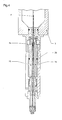
- the spring or an analogous element 54 is designed so that a rotation of the square bar 51 around the pins 62, 63 is possible, for which it is a prerequisite that the in the bores 51.1 and 51.2 of the square bar 51 projecting portions of the two Pins 62, 63 have a defined, smaller diameter than the holes 51.1 or 51.2 itself, so that the square bar 51 upon rotation about the pins 62, 63 can escape laterally.
- the upper pin 63 carries a piston 63.1, the sealing in a cylinder chamber 68 is guided, in which a pressure medium connection 69 opens.
- a pressure medium connection 69 opens.
- the piston 63.1 and thus the pin 63 pressed down against the force of a return spring 70, thereby simultaneously also the square bar 51 against the force of the lower return spring 64 after down is adjusted. Since the axes of the pins 62, 63 laterally offset to the axes the holes 51.1; 51.2 are away from the through the support surfaces 52.1; 52.1 formed corner, the square bar 51 is about the tapered ends the pin 62, 63 moved away from this corner, whereby the thread channel 67 for Purpose of Faden tofädelung is increased.
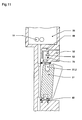
- the square bar 51 can according to Figure 11 in retracted into the cylinder chamber 68 Pivot 63 by hand laterally swung out of the support block 52 be, for which the lower sealing ring 60 must have sufficient elasticity.
- This exchange is not too confused with the example shown in Figure 12 apparent turning a square bar 51, to differently flattened longitudinal edges of the same square bar 51 in comparison with the through the two support surfaces 52.1, 52.2 to bring educated corner.
- FIG. 9 shows the yarn F leaving the yarn treatment chamber 59, which, like FIG in the case of the device according to Figures 1 - 6, the between the two support surfaces 52.1, 52.2 and the square bar 51 formed thread channel 67 seals.
- the inlet-side end of the treatment or pressure chamber 59 is a corresponding System as described with reference to FIGS. 7-12.
Landscapes
- Engineering & Computer Science (AREA)
- Textile Engineering (AREA)
- Treatment Of Fiber Materials (AREA)
- Yarns And Mechanical Finishing Of Yarns Or Ropes (AREA)
Abstract
Ein Verfahren zur Behandlung eines Fadens mit einem gas- oder dampfförmigen Medium,
ist dadurch gekennzeichnet, daß man den Faden durch einen zwischen zwei
länglichen, relativ zueinander gegen Feder- oder Magnetkraft verstellbaren Fadenführungselementen
(15, 16) angebrachten Fadenkanal in eine gegenüber der Umgebung
im wesentlichen abgedichtete Fadenbehandlungskammer (2) einlaufen läßt, der man
das gas- oder dampfförmige Medium unter Überdruck zuleitet, und daß man den Faden
anschließend durch einen weiteren, zwischen zwei länglichen, gegen Feder- oder
Magnetkraft relativ zueinander verstellbaren Fadenführungselementen (15, 16) angebrachten
Fadenkanal abzieht, wobei man den Querschnitt der beiden Fadenkanäle auf
die Dicke (Titer) des Fadens derart abstimmt, daß der Faden diese Kanäle im
wesentlichen reibungslos durchläuft und weitgehend gegen Druckverluste aus der
Kammer abdichtet.
Description
Die Erfindung betrifft ein Verfahren und eine Vorrichtung zur Behandlung eines Fadens mit einem gas- oder dampfförmigen Medium.The invention relates to a method and a device for treating a thread with a gaseous or vaporous medium.
Um einem Faden bestimmte Eigenschaften zu erteilen, ist es bekannt, eine Fadenspule oder auch eine bestimmte Fadenmenge in einer offenen oder geschlossenen Kammer entweder unter Atmosphärendruck oder unter Überdruck mit einem auf die erwünschten Eigenschaften abgestimmten, gas- oder dampfförmigen Medium chargenweise zu behandeln.In order to impart certain properties to a thread, it is known to use a thread bobbin or a certain amount of thread in an open or closed Chamber either under atmospheric pressure or under pressure with a on the desired properties tuned gas or vapor medium in batches to treat.
Für eine Doppeldraht-Zwirnspindel ist es aus der DE 28 11 583 C 1 bekannt, auf einen
laufenden Faden mittels einer Blasdüse ein dampf- oder gasförmiges Behandlungsmedium
bei Atmosphärendruck aufzublasen. For a double-twisting spindle, it is known from DE 28 11 583
Der Erfindung liegt die Aufgabe zugrunde, ein Verfahren und eine Vorrichtung zu schaffen, mit denen es möglich ist, einen laufenden Faden mit einem unter Druck stehenden, gas- oder dampfförmigen Medium zu behandeln, da sich bei Überdruck das Medium über den Querschnitt des Fadens dichter an die Einzelkapillare einbringen läßt, insbesondere wenn die Fadenspannung gering ist.The invention has for its object to provide a method and an apparatus create, with which it is possible a running thread with a under pressure stationary, gaseous or vaporous medium to be treated, since at overpressure bring the medium closer to the single capillary over the cross section of the thread leaves, especially if the thread tension is low.
Diese Aufgabe wird mit einem Verfahren gemäß Anspruch 1 und mit einer Vorrichtung
gemäß Anspruch 3 gelöst.This object is achieved with a method according to
Erfindungsgemäß sind einer von einem Faden durchlaufenen Fadenbehandlungskammer , die einen Druckkammerabschnitt aufweist, in den unter Druck stehendes Behandlungsmedium eingeblasen wird, einlaufseitig und auslaufseitig "Fadenschleusen" vor- bzw. nachgeschaltet, bei denen der laufende Faden selbst die Funktion eines Abdichtelementes hat, um einen unbeabsichtigten Austritt des unter Druck stehenden Behandlungsmediums aus der Fadenbehandlungskammer so weit wie möglich zu verhindern. Die einzelne Fadenschleuse muß dabei so gestaltet sein, daß sie von Fadenverdickungen, zum Beispiel Knotstellen oder dergleichen, durchlaufen werden kann, wobei weiterhin auch die Möglichkeit einer vorzugsweise pneumatischen Fadendurchfädelung gegeben sein soll.According to the invention, a thread treatment chamber passed through by a thread , which has a pressure chamber portion in the under pressure stationary treatment medium is injected, inlet side and outlet side Forward or downstream "thread locks", in which the current thread itself Function of a sealing element has to prevent inadvertent leakage of the Pressured treatment medium from the yarn treatment chamber so far as possible to prevent. The single yarn sluice must be designed that they of thread thickening, for example Knotstellen or the like, go through may be, and still the possibility of a preferably pneumatic thread threading should be given.
Bevorzugte Ausführungsformen der Erfindung sind in Unteransprüchen behandelt.Preferred embodiments of the invention are dealt with in subclaims.
Die Erfindung wird im folgenden anhand der Zeichnungen näher beschrieben.
Figur 1 zeigt in schematischer Darstellung eine Seitenansicht eines nicht zur Erfindung
gehörenden Aufwickelaggregats, bestehend aus einem Spulenträgerrahmen 1
zur Lagerung einer Spulenhülse bzw. Spule Sp, einer die Spule Sp antreibende Friktionsantriebswalze
und einem Changierfadenführer 4.Figure 1 shows a schematic representation of a side view of a not to the invention
belonging Aufwickelaggregats, consisting of a bobbin frame. 1
for supporting a bobbin tube or spool Sp, a spool driving Sp friction drive roller
and a traversing
Die erfindungsgemäße Vorrichtung enthält als Teil einer Fadenbehandlungskammer
x einen Druckkammerabschnitt 5 mit einem Anschluß 6 zum Einblasen eines unter
Druck stehenden, gas- oder dampfförmigen Behandlungsmediums durch eine Düse 7,
deren Ausströmöffnung eine Prallfläche 8 gegenüberliegen kann. Die Fadenbehandlungskammer
2 ist mit sich diametral gegenüberliegenden Einlauf- bzw. Auslauföffnungen
versehen, in die abdichtend Fadenschleusen A und B eingesetzt sind,
die in wesentlichen Teilen identisch miteinander sind, mit der Ausnahme, daß der
unteren Fadenschleuse B ein Druckluftinjektor 9 zum Durchfädeln eines Fadens
durch die Fadenschleusen A und B und die Fadenbehandlungskammer 2 zugeordnet
ist. Innerhalb der Fadenbehandlungskammer 2 sind zwei schematisiert dargestellte
Fadenlieferwerke 10 und 11 angeordnet, um den Faden F im wesentlichen spannungsfrei
durch die Fadenbehandlungskammer 2 und den Druckkammerabschnitt 5
zu fördern.The device according to the invention contains as part of a thread treatment chamber
x a
Gemäß den Figuren 1 und 2 besteht jede die Fadenschleuse A und B aus folgenden Einzelteilen:
- einen in eine untere oder obere Öffnung der
Fadenbehandlungskammer 2 abdichtendeingesetzten Anschlußstutzen 12; - ein an den
Anschlußstutzen 12angesetztes Zylindergehäuse 13; - einen in das Ende des
Zylindergehäuses 13eingesetzten Rohrstutzen 14; - zwei innerhalb des
Zylindergehäuses 13 untergebrachte,längliche Fadenführungselemente - einen innerhalb des
Zylindergehäuses 13verschiebbaren Kolben 17; - eine den
Kolben 17abstützende Rückstellfeder 18; - eine die
Fadenführungselemente abstützende Rückstellfeder 19; - eine die beiden
Fadenführungselemente drückende Ringfeder 20, die auch ein O-Ring sein kann; - sowie übliche Dichtungselemente, beispielsweise in Form von
Ringdichtungen 21.
- a connecting
pipe 12 sealingly inserted into a lower or upper opening of theyarn treatment chamber 2; - a attached to the connecting
piece 12cylinder housing 13; - a
pipe socket 14 inserted into the end of thecylinder housing 13; - two elongate
thread guide elements cylinder housing 13 and having a substantially semicircular cross-section, of which at least one has a longitudinal recess 16.1 or 15.1 for forming a thread channel according to FIGS. 2a and 2b; - a displaceable within the
cylinder housing 13piston 17; - a
piston 17 supporting thereturn spring 18; - a
thread guide elements return spring 19; - a two
thread guide elements oppressive ring spring 20, which may also be an O-ring; - and conventional sealing elements, for example in the form of ring seals 21st
Der Anschlußstutzen 12 ist bei der in Figur 2 dargestellten unteren Fadenschleuse B
mit einem nach unten ragenden Zentrier- und Spreizkegel 12.1 versehen. Der Kolben
17 ist an seiner Oberseite mit einem nach oben ragenden Zentrier- bzw. Spreizkegel
17.1 versehen. Die beiden Fadenführungselemente 15 und 16 sind an ihren oberen
und unteren Enden so gestaltet, daß sie zusammen eine im wesentlichen
kegelförmige Einlauf- bzw. Auslaßöffnung begrenzen, in die die Zentrier- bzw.
Spreizkegel 12.1 bzw. 17.1 ragen bzw. aufgrund der federnden Abstützung einerseits
der Fadenführungselemente 15, 16 und andererseits des Kolbens 17 einfahrbar sind.The connecting
Die Ausführungsform gemäß Figur 3 unterscheidet sich von der Ausführungsform
gemäß Figur 2 dadurch, daß anstelle einer Ringfeder 20 sich gegenüberliegende Magnete
22 vorgesehen sind, um die beiden Fadenführungselemente gegeneinander zu
drücken.The embodiment according to FIG. 3 differs from the embodiment
according to Figure 2, characterized in that instead of an
Die Fadenschleusen müssen besondere Merkmale haben:
- Reibungsarm und verschleißfrei;
- Knotendurchlässigkeit ohne merkliche Fadenspannungserhöhung;
- gute Einfädelbarkeit für einen Faden;
- Abdichtung des Behandlungsraumes zur Atmosphäre, um unbeabsichtigte Verluste an Behandlungsmedium (Dampf, spezielle Gase, Druckluft) möglichst gering zu halten.
- Low friction and wear-free;
- Knot permeability without noticeable increase of thread tension;
- good threadability for a thread;
- Sealing of the treatment room to the atmosphere in order to minimize accidental losses of treatment medium (steam, special gases, compressed air).
Der durch die beiden vorzugsweise geschliffenen Fadenführungselemente 15, 16
gebildete Fadenkanal hat einen Fadendurchlaßquerschnitt, der im wesentlichen dem
Titer bzw. dem Querschnitt des zu verarbeitenden textilen Fadens entspricht. Durch
diese Maßnahme verschließt der durchlaufende Faden im wesentlichen den Fadenkanal
für das unter Druck stehende Behandlungsmedium, so daß nur minimale Verluste
an Behandlungsmedium auftreten. Der Überdruck des noch mit dem Faden durch den
Fadenkanal strömenden Behandlungsmediums kann die beiden Fadenführungselemente
15, 16 nicht auseinander drücken, da die wirksame Druckfläche sehr gering
ist, im wesentlichen beschränkt auf Fadendurchmesser mal Länge des Fadendurchlaufkanals.
Diesem Druck wirkt die die beiden Führungselemente 15,16 zusammenhaltende
Ringfeder entgegen. Anstelle einer Ringfeder kann auch ein O-Ring oder es
könnten Magnete 22 (Figur 3) vorgesehen sein.The by the two preferably ground
Der durchlaufende Faden zentriert sich zwischen den beiden Führungselementen, da
er den Weg des geringsten Reibungswiderstandes sucht. Dadurch werden keine Faserkapillare
zwischen den Fadenführungselementen 15, 16 eingeklemmt.The continuous thread is centered between the two guide elements, since
he seeks the path of the least frictional resistance. As a result, no Faserkapillare
between the
Die beiden Fadenführungselemente werden bei durchlaufendem Faden über die beiden unteren und oberen Zentrier- bzw. Spreizkegel 12.1 und 17.1 zentriert, und zwar in Zusammenwirken mit den konischen Einlauf- bzw. Auslauföffnungen an den oberen und unteren Enden der Fadenführungselemente.The two thread guide elements are on passing thread over the two centered lower and upper centering or expanding cone 12.1 and 17.1, and indeed in cooperation with the conical inlet and outlet openings at the top and lower ends of the thread guide elements.
Gemäß den Figuren 4 und 5 öffnet ein durch die Fadenschleuse B hindurchlaufender Knoten (Fadenverdickung) den Fadenkanal zwischen den beiden Fadenführungselementen, die gegen die Kraft der Ringfeder 20 (bzw. der Magnete 22) nach außen gedrückt werden. Die dabei auftretenden, geringen seitlichen Druckmediumverluste beim Knotendurchlauf sind zu vernachlässigen. Nach dem Durchlaufen des Knotens durch die "Fadenschleuse" wird der Fadenkanal wieder geschlossen. According to FIGS. 4 and 5, a thread passing through the thread lock B opens Knot (thread thickening) the thread channel between the two thread guide elements, against the force of the annular spring 20 (or the magnets 22) to the outside be pressed. The occurring, small lateral pressure medium losses in the knot run are negligible. After passing through the knot through the "thread lock" the thread channel is closed again.
Der während des Öffnens des Fadenkanals kurzzeitig auf die größer werdenden Trennflächen der Fadenführungselemente wirkende Druck des Behandlungsmediums wirkt sich nicht aus, da sich dieser Druck entsprechend auch auf den Außenseiten der beiden Fadenführungselemente aufbaut.The short while opening the thread channel on the growing Separating surfaces of the thread guide elements acting pressure of the treatment medium does not affect itself, since this pressure accordingly also on the outsides of the builds up both thread guide elements.
Zum Einfädeln des Fadens durch die beiden Fadenschleusen werden die Fadenführungselemente
15, 16 mittels des Kolbens 17 gegen die Kraft der Rückstellfeder 19
nach oben geschoben, wenn der Kolben 17 durch den Druckluftanschluß 23 mit
Druckluft beaufschlagt wird. Wie in Figur 6 dargestellt, werden die beiden Zentrier-
bzw. Spreizkegel 12.1 und 17.1 in die konischen Einlauf- bzw. Auslauföffnungen
eingefahren, wodurch die beiden Fadenführungselemente 15, 16 über ihre gesamte
Länge auseinandergedrückt werden, so daß ein für die pneumatische Fadendurchfädelung
ausreichend großer Öffnungsquerschnitt vorhanden ist. Für die Fadendurchfädelung
wird der Druckluftinjektor 9 in bekannter Weise mit Druckluft beaufschlagt,
um einen im Bereich der Fadenschleusen A und B und der Druckkammer 5
wirksamen Saugstrom zu erzeugen.For threading the thread through the two thread locks become the
Nach dem Einfädeln des Fadens wird der Kolben 17 druckentlastet, so daß die beiden
Fadenführungselemente 15, 16 sowie der Kolben 17 wieder in ihre Ausgangsstellung
zurückgestellt werden.After threading the thread of the
Die beiden Fadenführungselemente 15, 16 der unteren Fadenschleuse B sind mit ihren
unteren Enden an einer Ringschulter des Gehäuses 13 abgestützt.The two
Bei der in den Figuren 7-12 dargestellten Ausführungsvariante weist die einzelne
Fadenschleuse ein erstes Fadenführungselement 51 in Form einer Mehrkantleiste,
vorzugsweise Vierkantleiste, auf, deren in Längsrichtung verlaufende Kanten in unterschiedlichen
Abständen zur Leistenachse abgeflacht sind. Das zweite Fadenführungselement
besteht aus zwei winkelig zueinander angeordneten Stützflächen 52.1;
52.2, gegen die die zwischen den abgeflachten Kanten befindlichen Außenflächen
der Vierkantleiste 51 mittels einer beispielsweise auf einen Hebel 55 einwirkenden
Feder 54 gedrückt werden. In the embodiment shown in Figures 7-12, the individual
Threadlock a first
Die beiden Stützflächen 52.1; 52.2 sind Teil eines Halterungsblockes 52, der zusätzlich
untere und obere Sitzflächen 52.3; 52.4 aufweist, zwischen denen die Vierkantleiste
51 in der in Figur 9 dargestellten Betriebsstellung mittels Dichtringen 60, 61
abgestützt ist. Die Vierkantleiste ist an ihrem unteren Ende mit einer zu ihrer Achsmitte
exzentrischen Blindbohrung 51.1 und an ihrer Oberseite mit einer zu der Bohrung
51.1 axial ausgerichteten Blindbohrung 51.2 versehen. Den Bohrungen 51.1
bzw. 51.2 liegen koaxial zueinander ausgerichtete Halterungszapfen 62 bzw. 63 gegenüber,
deren in die Bohrungen 51.1 bzw. 51.2 ragenden Enden im wesentlichen die
Form eines Kegels haben. Die Achsen der Zapfen 62, 63 liegen exzentrisch zu den
Achsen der beiden Blindbohrungen 51.1, 51.2. Eine auf die Unterseite der Vierkantleiste
51 wirkende Druckfeder 64 drückt die Vierkantleiste 51 in den in den
Figuren 9 und 10 dargestellten Betriebspositionen gegen den oberen Dichtungsring
61.The two support surfaces 52.1; 52.2 are part of a
An die einen Teil der Fadenbehandlungskammer 2 bildende, mit Fadenlieferwerken
bestückte Druckkammer 59 schließt ein durch den Halterungsblock 52 geführter Fadenkanal
65 an, dem im unteren Bereich des Halterungsblockes 52, im wesentlichen
beginnend mit der unteren Sitzfläche 52.3, axial ausgerichtet ein Fadenkanal 66
gegenüberliegt. Die beiden Fadenkanäle 65, 66 münden in den durch die beiden
Stützflächen 52.1, 52.2 und die gegenüberliegende abgeflachte Kante der Vierkantleiste
51 gebildeten Fadenkanal 67.At the one part of the
An dem Halterungsblock 52 sind zum Abdichten der Spalte zwischen der Vierkantleiste
51 und den Stützflächen 51.1; 51.2 Dichtelemente 53 vorzugsweise in Form
von Dichtlappen angeordnet.On the
Die Feder oder ein analoges Element 54 ist so ausgelegt, daß eine Drehung der Vierkantleiste
51 um die Zapfen 62, 63 möglich ist, wofür es Voraussetzung ist, daß die
in die Bohrungen 51.1 bzw. 51.2 der Vierkantleiste 51 ragenden Abschnitte der beiden
Zapfen 62, 63 einen definierten, kleineren Durchmesser haben als die Bohrungen
51.1 bzw. 51.2 selbst, so daß die Vierkantleiste 51 bei Drehung um die Zapfen 62, 63
seitlich ausweichen kann. The spring or an
Der obere Zapfen 63 trägt einen Kolben 63.1, der in einer Zylinderkammer 68 abdichtend
geführt ist, in die ein Druckmittelanschluß 69 mündet. Bei Beaufschlagung
der Zylinderkammer 68 mit Druckmittel werden der Kolben 63.1 und damit der Zapfen
63 gegen die Kraft einer Rückstellfeder 70 nach unten gedrückt, wodurch gleichzeitig
auch die Vierkantleiste 51 gegen die Kraft der unteren Rückstellfeder 64 nach
unten verstellt wird. Da die Achsen der Zapfen 62, 63 seitlich versetzt zu den Achsen
der Bohrungen 51.1; 51.2 liegen und zwar weg von der durch die Stützflächen 52.1;
52.1 gebildeten Ecke, wird die Vierkantleiste 51 mittlels der kegelförmigen Enden
der Zapfen 62, 63 aus dieser Ecke weggerückt, wodurch der Fadenkanal 67 zum
Zweck der Fadendurchfädelung vergrößert wird.The
Die Vierkantleiste 51 kann gemäß Figur 11 bei in die Zylinderkammer 68 eingefahrenem
Zapfen 63 von Hand seitlich aus dem Halterungsblock 52 herausgeschwenkt
werden, wofür der untere Dichtring 60 eine ausreichende Elastizität haben muß. Auf
diese Weise besteht die Möglichkeit, Vierkantleisten mit unterschiedlich abgeflachten
Kantenabmessungen gegeneinander auszutauschen. Dieser Austausch ist nicht zu
verwechseln mit dem beispielsweise aus Figur 12 ersichtlichen Drehen einer Vierkantleiste
51, um unterschiedlich abgeflachte Längskanten ein und derselben Vierkantleiste
51 in Gegenüberstellung mit der durch die beiden Stützflächen 52.1, 52.2
gebildeten Ecke zu bringen.The
Figur 9 zeigt den die Fadenbehandlungskammer 59 verlassenden Faden F, der, wie
im Fall der Vorrichtung gemäß den Figuren 1 - 6, den zwischen den beiden Stützflächen
52.1, 52.2 und der Vierkantleiste 51 gebildeten Fadenkanal 67 abdichtet. Am
einlaufseitigen Ende der Behandlungs- bzw. Druckkammer 59 ist ein entsprechendes
System, wie anhand der Figuren 7-12 beschrieben, angebracht.FIG. 9 shows the yarn F leaving the
Um beim Einlaufen einer Fadenverdickung Fn in den Fadenkanal 67 Beschädigungen
des Fadens zu vermeiden und das Einfädeln eines Fadens in den Fadenkanal 67 zu
erleichtern, sind die Abflachungen der Vierkantleiste 51 im Bereich mindestens einer
Stirnseite der Vierkantleiste 51 nach innen hin angefast. To damage when entering a thread thickening Fn in the
- A + BA + B
- Fadenschleusenthread locks
- 11
- SpulenträgerrahmenCoil support frame
- 22
- SpuleKitchen sink
- 33
- Antriebswalzedrive roller
- 44
- ChangierfadenführerTraversing thread guide
- 55
- Druckkammerpressure chamber
- 66
- DrucklufteinlaßCompressed air inlet
- 77
- Düsejet
- 88th
- Prallflächebaffle
- 99
- Druckluftinjektorcompressed air injector
- 10+1110 + 11
- FadenlieferwerkeYarn feeding stations
- 1212
-
Anschlußstutzen
- 12.1
- Spreizkegel
- 12.1
- expanding cone
- 1313
- Zylindergehäusecylinder housing
- 1414
- Rohrstutzenpipe socket
- 1515
-
Fadenführungselement
- 15.1
- Nut
- 15.1
- groove
- 1616
-
Fadenführungselement
- 16.1
- Nut
- 16.1
- groove
- 1717
- Kolbenpiston
- 1818
- RückstellfederReturn spring
- 1919
- RückstellfederReturn spring
- 2020
- RingfederRingfeder
- 2121
- Ringdichtungring seal
- 2222
- Magnetenmagnets
- 23 2423 24
- DrucklufteinlaßCompressed air inlet
- 2525
- Fadenumlenkrollethread return roller
- 5151
- Mehrkant-VierkantleistePolygonal square bar
- 51.1/251.1 / 2
- Blindbohrungenblind holes
- 5252
- Halterungsblockmounting block
- 52.1; 52.252.1; 52.2
- Stützflächensupport surfaces
- 52.3; 52.452.3; 52.4
- untere / obere Sitzflächelower / upper seat
- 5353
- Federelementespring elements
- 5454
- Feder - ZugfederSpring - tension spring
- 5555
- Hebellever
- 5959
- DruckkammerabschnittPressure chamber portion
- 60,6160.61
- Dichtringeseals
- 6262
- Halterungszapfensupport posts
- 6363
- Halterungszapfen 63.1 KolbenRetaining plug 63.1 Piston
- 6464
- Druckfedercompression spring
- 6565
- Fadenkanalthread channel
- 6666
- Fadenkanalthread channel
- 6767
- Fadenkanalthread channel
- 6868
- Zylinderkammercylinder chamber
- 6969
- DruckmittelanschlußFluid port
Claims (25)
Applications Claiming Priority (2)
| Application Number | Priority Date | Filing Date | Title |
|---|---|---|---|
| DE10348278 | 2003-10-17 | ||
| DE10348278A DE10348278A1 (en) | 2003-10-17 | 2003-10-17 | Method and device for treating a running thread with a gaseous and vaporous treatment medium |
Publications (3)
| Publication Number | Publication Date |
|---|---|
| EP1528129A2 true EP1528129A2 (en) | 2005-05-04 |
| EP1528129A3 EP1528129A3 (en) | 2007-03-21 |
| EP1528129B1 EP1528129B1 (en) | 2011-07-27 |
Family
ID=34399535
Family Applications (1)
| Application Number | Title | Priority Date | Filing Date |
|---|---|---|---|
| EP04018188A Expired - Lifetime EP1528129B1 (en) | 2003-10-17 | 2004-07-31 | Method and device for treating an advancing yarn with a gaseous or vaporous medium |
Country Status (6)
| Country | Link |
|---|---|
| US (1) | US7475573B2 (en) |
| EP (1) | EP1528129B1 (en) |
| JP (1) | JP4611709B2 (en) |
| CN (1) | CN100557105C (en) |
| AT (1) | ATE518029T1 (en) |
| DE (1) | DE10348278A1 (en) |
Cited By (2)
| Publication number | Priority date | Publication date | Assignee | Title |
|---|---|---|---|---|
| DE102007014556A1 (en) | 2007-03-27 | 2008-10-02 | Resch Maschinenbau Gmbh | Combination method e.g. for generating textile thread, involves combining different steps so that textile is twisted, and then arranged with corresponding device to provide certain form |
| EP2388363A1 (en) * | 2010-05-20 | 2011-11-23 | Oerlikon Textile GmbH & Co. KG | Thread sluice for sealing a pressurised thread processing chamber |
Families Citing this family (15)
| Publication number | Priority date | Publication date | Assignee | Title |
|---|---|---|---|---|
| DE102006040065A1 (en) | 2006-08-26 | 2008-02-28 | Oerlikon Textile Gmbh & Co. Kg | Procedure for thermal treatment of a running yarn at a twisting machine with workplaces, comprises passing the yarn by a delivery mechanisms to a device for the thermal treatment of the yarn in tension free manner and spooling the yarn |
| DE102007038375B3 (en) * | 2007-08-14 | 2009-01-15 | Power-Heat-Set Gmbh | Heat Setting container |
| WO2012108230A1 (en) * | 2011-02-10 | 2012-08-16 | 三菱レイヨン株式会社 | Device for treating carbon-fiber-precursor acrylic yarn with pressurized steam, and process for producing acrylic yarn |
| US9175429B2 (en) * | 2011-03-09 | 2015-11-03 | Mitsubishi Rayon Co., Ltd. | Apparatus for pressure steam treatment of fiber bundle and producing method of carbon fiber precursor fiber bundle |
| DE102011108112A1 (en) * | 2011-07-20 | 2013-01-24 | Oerlikon Textile Gmbh & Co. Kg | Garnbehandlungskammer |
| IN2014CN02444A (en) * | 2011-09-09 | 2015-06-19 | Oerlikon Textile Gmbh & Co Kg | |
| CN103526371A (en) * | 2013-08-27 | 2014-01-22 | 宁波宜科科技实业股份有限公司 | Wet-state spinning method and wet spraying device for hemp fibers |
| CN103541125A (en) * | 2013-11-12 | 2014-01-29 | 侯如升 | Ribbon guiding device of ribbon loom |
| CN103757781B (en) * | 2014-02-12 | 2016-03-30 | 鲁丰织染有限公司 | A kind of warping slashing technique of linen thread and yarn |
| CN104032506B (en) * | 2014-05-28 | 2016-06-01 | 苏州潮盛印花制版实业有限公司 | A kind of pipe cylinder quetsch |
| CN106319660A (en) * | 2016-11-22 | 2017-01-11 | 江苏新豪威特种化纤有限公司 | Filament steam heating device to prevent air leakage |
| DE102019003801A1 (en) * | 2019-05-28 | 2020-12-03 | Oerlikon Textile Gmbh & Co. Kg | Heating device for heating a running thread |
| CN110485005B (en) * | 2019-08-22 | 2020-09-11 | 浙江晨宇化纤有限公司 | Device for increasing softness and strength of yarns |
| CN115726071A (en) * | 2022-11-18 | 2023-03-03 | 东华大学 | Drawing and humidifying method suitable for dry spinning of pure flax short fibers |
| CN116815373B (en) * | 2023-05-23 | 2025-09-05 | 山东广泰机械科技有限公司 | A novel yarn processing system and method |
Family Cites Families (16)
| Publication number | Priority date | Publication date | Assignee | Title |
|---|---|---|---|---|
| US2708843A (en) * | 1950-08-10 | 1955-05-24 | Chemstrand Corp | Fluid treating apparatus for strands |
| US3012427A (en) * | 1961-04-04 | 1961-12-12 | American Cyanamid Co | Pressure-sealing device |
| US3040553A (en) * | 1961-05-19 | 1962-06-26 | Crompton & Knowles Corp | Sealing of pressure vessels |
| US3126724A (en) * | 1963-01-21 | 1964-03-31 | kolonits | |
| DE1460265A1 (en) * | 1963-05-11 | 1969-01-02 | Kleinewefers Soehne J | Impregnation device for wide goods, especially for textiles |
| GB1049947A (en) * | 1963-05-11 | 1966-11-30 | Kleinewefers Gmbh | Improvements in or relating to sealing devices |
| JPS4841475B1 (en) * | 1969-07-05 | 1973-12-06 | ||
| JPS503831B2 (en) * | 1971-10-07 | 1975-02-10 | ||
| CH594761A5 (en) * | 1976-02-12 | 1978-01-31 | Heberlein & Co Ag | Heating device seal for polyamide or polyester yarns |
| JPS5470382A (en) * | 1977-11-16 | 1979-06-06 | Kobunshi Kako Kenkyusho | Method of processing tire cord |
| WO1984002358A1 (en) * | 1982-12-18 | 1984-06-21 | Barmag Barmer Maschf | Heating chamber for continuous filaments |
| DE8236130U1 (en) * | 1982-12-23 | 1984-05-30 | Barmag Barmer Maschinenfabrik Ag, 5630 Remscheid | THREAD HEATING CHAMBER FOR RUNNING THREADS |
| JPS60105696U (en) * | 1983-12-22 | 1985-07-18 | 東レエンジニアリング株式会社 | Moving object processing equipment |
| US6139588A (en) * | 1996-11-22 | 2000-10-31 | University Of Manchester Institute Of Science And Technology | Processing textile structures |
| US6735934B1 (en) * | 1999-02-16 | 2004-05-18 | Temco Textilmaschinenkomponenten Gmbh | Method for feeding in and starting a thread and false twist texturing device |
| EP1348785A1 (en) * | 2002-03-28 | 2003-10-01 | Power- heat-set GmbH | Device for treating elongated goods, especially thread like textile yarns |
-
2003
- 2003-10-17 DE DE10348278A patent/DE10348278A1/en not_active Withdrawn
-
2004
- 2004-07-31 AT AT04018188T patent/ATE518029T1/en active
- 2004-07-31 EP EP04018188A patent/EP1528129B1/en not_active Expired - Lifetime
- 2004-09-20 CN CNB2004100780476A patent/CN100557105C/en not_active Expired - Fee Related
- 2004-10-15 US US10/966,499 patent/US7475573B2/en not_active Expired - Fee Related
- 2004-10-18 JP JP2004303429A patent/JP4611709B2/en not_active Expired - Fee Related
Cited By (2)
| Publication number | Priority date | Publication date | Assignee | Title |
|---|---|---|---|---|
| DE102007014556A1 (en) | 2007-03-27 | 2008-10-02 | Resch Maschinenbau Gmbh | Combination method e.g. for generating textile thread, involves combining different steps so that textile is twisted, and then arranged with corresponding device to provide certain form |
| EP2388363A1 (en) * | 2010-05-20 | 2011-11-23 | Oerlikon Textile GmbH & Co. KG | Thread sluice for sealing a pressurised thread processing chamber |
Also Published As
| Publication number | Publication date |
|---|---|
| US7475573B2 (en) | 2009-01-13 |
| EP1528129B1 (en) | 2011-07-27 |
| US20050102764A1 (en) | 2005-05-19 |
| JP2005120570A (en) | 2005-05-12 |
| DE10348278A1 (en) | 2005-05-25 |
| CN100557105C (en) | 2009-11-04 |
| EP1528129A3 (en) | 2007-03-21 |
| JP4611709B2 (en) | 2011-01-12 |
| ATE518029T1 (en) | 2011-08-15 |
| CN1609298A (en) | 2005-04-27 |
Similar Documents
| Publication | Publication Date | Title |
|---|---|---|
| EP1528129A2 (en) | Method and device for treating an advancing yarn with a gaseous or vaporous medium | |
| DE3538744C2 (en) | ||
| EP0114298B1 (en) | Heating chamber for running yarns | |
| ZA200102485B (en) | Device for arranging, clamping or contracting a ring-shaped securing mechanism. | |
| EP0205627A1 (en) | Process for obtaining a leakless double-seat valve with washing of the seats, and device for carrying out the process | |
| DE19543631C2 (en) | Texturing method and apparatus | |
| DE2339603C3 (en) | Method for starting injector nozzles and device for carrying out the method | |
| DE69419285T2 (en) | Gas discharge connection to be cleaned for compressed gas cylinders | |
| EP0061415A1 (en) | Valve for hydraulic systems | |
| DE2220977A1 (en) | Device for handling yarn | |
| EP0539808A1 (en) | Apparatus for stuffer crimping synthetic filament yarns | |
| EP1689940A1 (en) | Through-flow volume limiters | |
| DE2702399A1 (en) | DEVICE FOR BRAKING SYSTEMS WITH A PRESSURE REGULATING DEVICE FOR BLOCKING CONTROL | |
| EP0527355A1 (en) | Method and apparatus for pneumatically inserting sliver in a spinning machine | |
| DE69217600T2 (en) | Nozzle device and method for treating yarn | |
| DE4033362C3 (en) | Device for reducing the pressure of a gaseous medium | |
| EP0144029B1 (en) | Cooling tube for a cooling section for rapidly cooling steel wire rod or rod stock | |
| EP4130361B1 (en) | Drafting arrangement and method for loading and opening the drafting frame | |
| DE10112045B4 (en) | Rundausbreiter for textile tubular fabric | |
| EP0821087A1 (en) | Open-end spinning device | |
| DE3000443A1 (en) | Tensioning device for two-for-one spindle - has spring capsule seated on pneumatic piston within cylindrical housing | |
| DE3873465T3 (en) | Valve specifically for automatic dispenser for independent breathing apparatus. | |
| DE2759703C2 (en) | ||
| DE2734220A1 (en) | Fibre texturising jet with an initial throttle section - prevents the build=up of false airstream patterns within the jet | |
| DE4137137A1 (en) | Pressure reducing device for gas flows - has regulator and throttle comprising valve housing with valve body having numerous flow channels directly connected to regulator step |
Legal Events
| Date | Code | Title | Description |
|---|---|---|---|
| PUAI | Public reference made under article 153(3) epc to a published international application that has entered the european phase |
Free format text: ORIGINAL CODE: 0009012 |
|
| AK | Designated contracting states |
Kind code of ref document: A2 Designated state(s): AT BE BG CH CY CZ DE DK EE ES FI FR GB GR HU IE IT LI LU MC NL PL PT RO SE SI SK TR |
|
| AX | Request for extension of the european patent |
Extension state: AL HR LT LV MK |
|
| PUAL | Search report despatched |
Free format text: ORIGINAL CODE: 0009013 |
|
| AK | Designated contracting states |
Kind code of ref document: A3 Designated state(s): AT BE BG CH CY CZ DE DK EE ES FI FR GB GR HU IE IT LI LU MC NL PL PT RO SE SI SK TR |
|
| AX | Request for extension of the european patent |
Extension state: AL HR LT LV MK |
|
| RIC1 | Information provided on ipc code assigned before grant |
Ipc: D02J 13/00 20060101ALI20070214BHEP Ipc: D06B 3/04 20060101ALI20070214BHEP Ipc: D06B 23/18 20060101AFI20070214BHEP |
|
| RAP1 | Party data changed (applicant data changed or rights of an application transferred) |
Owner name: OERLIKON TEXTILE GMBH & CO. KG |
|
| 17P | Request for examination filed |
Effective date: 20070911 |
|
| AKX | Designation fees paid |
Designated state(s): AT BE BG CH CY CZ DE DK EE ES FI FR GB GR HU IE IT LI LU MC NL PL PT RO SE SI SK TR |
|
| RAP1 | Party data changed (applicant data changed or rights of an application transferred) |
Owner name: OERLIKON TEXTILE GMBH & CO. KG |
|
| GRAP | Despatch of communication of intention to grant a patent |
Free format text: ORIGINAL CODE: EPIDOSNIGR1 |
|
| GRAS | Grant fee paid |
Free format text: ORIGINAL CODE: EPIDOSNIGR3 |
|
| GRAA | (expected) grant |
Free format text: ORIGINAL CODE: 0009210 |
|
| AK | Designated contracting states |
Kind code of ref document: B1 Designated state(s): AT BE BG CH CY CZ DE DK EE ES FI FR GB GR HU IE IT LI LU MC NL PL PT RO SE SI SK TR |
|
| REG | Reference to a national code |
Ref country code: GB Ref legal event code: FG4D Free format text: NOT ENGLISH |
|
| REG | Reference to a national code |
Ref country code: CH Ref legal event code: EP |
|
| REG | Reference to a national code |
Ref country code: DE Ref legal event code: R096 Ref document number: 502004012720 Country of ref document: DE Effective date: 20110922 |
|
| REG | Reference to a national code |
Ref country code: NL Ref legal event code: VDEP Effective date: 20110727 |
|
| BERE | Be: lapsed |
Owner name: OERLIKON TEXTILE G.M.B.H. & CO. KG Effective date: 20110731 |
|
| PG25 | Lapsed in a contracting state [announced via postgrant information from national office to epo] |
Ref country code: NL Free format text: LAPSE BECAUSE OF FAILURE TO SUBMIT A TRANSLATION OF THE DESCRIPTION OR TO PAY THE FEE WITHIN THE PRESCRIBED TIME-LIMIT Effective date: 20110727 Ref country code: FI Free format text: LAPSE BECAUSE OF FAILURE TO SUBMIT A TRANSLATION OF THE DESCRIPTION OR TO PAY THE FEE WITHIN THE PRESCRIBED TIME-LIMIT Effective date: 20110727 Ref country code: SE Free format text: LAPSE BECAUSE OF FAILURE TO SUBMIT A TRANSLATION OF THE DESCRIPTION OR TO PAY THE FEE WITHIN THE PRESCRIBED TIME-LIMIT Effective date: 20110727 Ref country code: PT Free format text: LAPSE BECAUSE OF FAILURE TO SUBMIT A TRANSLATION OF THE DESCRIPTION OR TO PAY THE FEE WITHIN THE PRESCRIBED TIME-LIMIT Effective date: 20111128 |
|
| PG25 | Lapsed in a contracting state [announced via postgrant information from national office to epo] |
Ref country code: MC Free format text: LAPSE BECAUSE OF NON-PAYMENT OF DUE FEES Effective date: 20110731 Ref country code: GR Free format text: LAPSE BECAUSE OF FAILURE TO SUBMIT A TRANSLATION OF THE DESCRIPTION OR TO PAY THE FEE WITHIN THE PRESCRIBED TIME-LIMIT Effective date: 20111028 Ref country code: PL Free format text: LAPSE BECAUSE OF FAILURE TO SUBMIT A TRANSLATION OF THE DESCRIPTION OR TO PAY THE FEE WITHIN THE PRESCRIBED TIME-LIMIT Effective date: 20110727 Ref country code: SI Free format text: LAPSE BECAUSE OF FAILURE TO SUBMIT A TRANSLATION OF THE DESCRIPTION OR TO PAY THE FEE WITHIN THE PRESCRIBED TIME-LIMIT Effective date: 20110727 Ref country code: CY Free format text: LAPSE BECAUSE OF FAILURE TO SUBMIT A TRANSLATION OF THE DESCRIPTION OR TO PAY THE FEE WITHIN THE PRESCRIBED TIME-LIMIT Effective date: 20110727 |
|
| REG | Reference to a national code |
Ref country code: IE Ref legal event code: FD4D |
|
| PG25 | Lapsed in a contracting state [announced via postgrant information from national office to epo] |
Ref country code: SK Free format text: LAPSE BECAUSE OF FAILURE TO SUBMIT A TRANSLATION OF THE DESCRIPTION OR TO PAY THE FEE WITHIN THE PRESCRIBED TIME-LIMIT Effective date: 20110727 Ref country code: CZ Free format text: LAPSE BECAUSE OF FAILURE TO SUBMIT A TRANSLATION OF THE DESCRIPTION OR TO PAY THE FEE WITHIN THE PRESCRIBED TIME-LIMIT Effective date: 20110727 Ref country code: IE Free format text: LAPSE BECAUSE OF FAILURE TO SUBMIT A TRANSLATION OF THE DESCRIPTION OR TO PAY THE FEE WITHIN THE PRESCRIBED TIME-LIMIT Effective date: 20110727 Ref country code: BE Free format text: LAPSE BECAUSE OF NON-PAYMENT OF DUE FEES Effective date: 20110731 |
|
| PG25 | Lapsed in a contracting state [announced via postgrant information from national office to epo] |
Ref country code: RO Free format text: LAPSE BECAUSE OF FAILURE TO SUBMIT A TRANSLATION OF THE DESCRIPTION OR TO PAY THE FEE WITHIN THE PRESCRIBED TIME-LIMIT Effective date: 20110727 Ref country code: EE Free format text: LAPSE BECAUSE OF FAILURE TO SUBMIT A TRANSLATION OF THE DESCRIPTION OR TO PAY THE FEE WITHIN THE PRESCRIBED TIME-LIMIT Effective date: 20110727 |
|
| PLBE | No opposition filed within time limit |
Free format text: ORIGINAL CODE: 0009261 |
|
| STAA | Information on the status of an ep patent application or granted ep patent |
Free format text: STATUS: NO OPPOSITION FILED WITHIN TIME LIMIT |
|
| PG25 | Lapsed in a contracting state [announced via postgrant information from national office to epo] |
Ref country code: DK Free format text: LAPSE BECAUSE OF FAILURE TO SUBMIT A TRANSLATION OF THE DESCRIPTION OR TO PAY THE FEE WITHIN THE PRESCRIBED TIME-LIMIT Effective date: 20110727 |
|
| 26N | No opposition filed |
Effective date: 20120502 |
|
| REG | Reference to a national code |
Ref country code: DE Ref legal event code: R097 Ref document number: 502004012720 Country of ref document: DE Effective date: 20120502 |
|
| REG | Reference to a national code |
Ref country code: AT Ref legal event code: MM01 Ref document number: 518029 Country of ref document: AT Kind code of ref document: T Effective date: 20110731 |
|
| PG25 | Lapsed in a contracting state [announced via postgrant information from national office to epo] |
Ref country code: AT Free format text: LAPSE BECAUSE OF NON-PAYMENT OF DUE FEES Effective date: 20110731 |
|
| PG25 | Lapsed in a contracting state [announced via postgrant information from national office to epo] |
Ref country code: ES Free format text: LAPSE BECAUSE OF FAILURE TO SUBMIT A TRANSLATION OF THE DESCRIPTION OR TO PAY THE FEE WITHIN THE PRESCRIBED TIME-LIMIT Effective date: 20111107 |
|
| PG25 | Lapsed in a contracting state [announced via postgrant information from national office to epo] |
Ref country code: LU Free format text: LAPSE BECAUSE OF NON-PAYMENT OF DUE FEES Effective date: 20110731 |
|
| PG25 | Lapsed in a contracting state [announced via postgrant information from national office to epo] |
Ref country code: BG Free format text: LAPSE BECAUSE OF FAILURE TO SUBMIT A TRANSLATION OF THE DESCRIPTION OR TO PAY THE FEE WITHIN THE PRESCRIBED TIME-LIMIT Effective date: 20111027 |
|
| PG25 | Lapsed in a contracting state [announced via postgrant information from national office to epo] |
Ref country code: HU Free format text: LAPSE BECAUSE OF FAILURE TO SUBMIT A TRANSLATION OF THE DESCRIPTION OR TO PAY THE FEE WITHIN THE PRESCRIBED TIME-LIMIT Effective date: 20110727 |
|
| REG | Reference to a national code |
Ref country code: DE Ref legal event code: R081 Ref document number: 502004012720 Country of ref document: DE Owner name: SAURER GERMANY GMBH & CO. KG, DE Free format text: FORMER OWNER: SAURER GMBH & CO. KG, 41069 MOENCHENGLADBACH, DE Effective date: 20110803 Ref country code: DE Ref legal event code: R081 Ref document number: 502004012720 Country of ref document: DE Owner name: SAURER GERMANY GMBH & CO. KG, DE Free format text: FORMER OWNER: OERLIKON TEXTILE GMBH & CO. KG, 42897 REMSCHEID, DE Effective date: 20130918 |
|
| REG | Reference to a national code |
Ref country code: GB Ref legal event code: 732E Free format text: REGISTERED BETWEEN 20140501 AND 20140507 |
|
| REG | Reference to a national code |
Ref country code: CH Ref legal event code: NV Representative=s name: SCHMAUDER AND PARTNER AG PATENT- UND MARKENANW, CH Ref country code: CH Ref legal event code: PUE Owner name: SAURER GERMANY GMBH AND CO. KG, DE Free format text: FORMER OWNER: OERLIKON TEXTILE GMBH AND CO. KG, DE |
|
| REG | Reference to a national code |
Ref country code: CH Ref legal event code: PCOW Free format text: NEW ADDRESS: LEVERKUSER STRASSE 65, 42897 REMSCHEID (DE) |
|
| REG | Reference to a national code |
Ref country code: FR Ref legal event code: TP Owner name: SAURER GERMANY GMBH & CO. KG, DE Effective date: 20141013 |
|
| REG | Reference to a national code |
Ref country code: FR Ref legal event code: PLFP Year of fee payment: 12 |
|
| PGFP | Annual fee paid to national office [announced via postgrant information from national office to epo] |
Ref country code: CH Payment date: 20150723 Year of fee payment: 12 Ref country code: GB Payment date: 20150723 Year of fee payment: 12 |
|
| PGFP | Annual fee paid to national office [announced via postgrant information from national office to epo] |
Ref country code: FR Payment date: 20150727 Year of fee payment: 12 |
|
| PGFP | Annual fee paid to national office [announced via postgrant information from national office to epo] |
Ref country code: IT Payment date: 20150731 Year of fee payment: 12 |
|
| PGFP | Annual fee paid to national office [announced via postgrant information from national office to epo] |
Ref country code: DE Payment date: 20160801 Year of fee payment: 13 |
|
| PGFP | Annual fee paid to national office [announced via postgrant information from national office to epo] |
Ref country code: TR Payment date: 20160725 Year of fee payment: 13 |
|
| REG | Reference to a national code |
Ref country code: CH Ref legal event code: PL |
|
| GBPC | Gb: european patent ceased through non-payment of renewal fee |
Effective date: 20160731 |
|
| PG25 | Lapsed in a contracting state [announced via postgrant information from national office to epo] |
Ref country code: FR Free format text: LAPSE BECAUSE OF NON-PAYMENT OF DUE FEES Effective date: 20160801 Ref country code: CH Free format text: LAPSE BECAUSE OF NON-PAYMENT OF DUE FEES Effective date: 20160731 Ref country code: LI Free format text: LAPSE BECAUSE OF NON-PAYMENT OF DUE FEES Effective date: 20160731 |
|
| REG | Reference to a national code |
Ref country code: FR Ref legal event code: ST Effective date: 20170331 |
|
| PG25 | Lapsed in a contracting state [announced via postgrant information from national office to epo] |
Ref country code: GB Free format text: LAPSE BECAUSE OF NON-PAYMENT OF DUE FEES Effective date: 20160731 |
|
| PG25 | Lapsed in a contracting state [announced via postgrant information from national office to epo] |
Ref country code: IT Free format text: LAPSE BECAUSE OF NON-PAYMENT OF DUE FEES Effective date: 20160731 |
|
| REG | Reference to a national code |
Ref country code: DE Ref legal event code: R119 Ref document number: 502004012720 Country of ref document: DE |
|
| PG25 | Lapsed in a contracting state [announced via postgrant information from national office to epo] |
Ref country code: DE Free format text: LAPSE BECAUSE OF NON-PAYMENT OF DUE FEES Effective date: 20180201 |
|
| PG25 | Lapsed in a contracting state [announced via postgrant information from national office to epo] |
Ref country code: TR Free format text: LAPSE BECAUSE OF NON-PAYMENT OF DUE FEES Effective date: 20170731 |