EP0527355A1 - Method and apparatus for pneumatically inserting sliver in a spinning machine - Google Patents
Method and apparatus for pneumatically inserting sliver in a spinning machine Download PDFInfo
- Publication number
- EP0527355A1 EP0527355A1 EP92112303A EP92112303A EP0527355A1 EP 0527355 A1 EP0527355 A1 EP 0527355A1 EP 92112303 A EP92112303 A EP 92112303A EP 92112303 A EP92112303 A EP 92112303A EP 0527355 A1 EP0527355 A1 EP 0527355A1
- Authority
- EP
- European Patent Office
- Prior art keywords
- sliver
- injector
- insertion funnel
- spinning machine
- nozzle
- Prior art date
- Legal status (The legal status is an assumption and is not a legal conclusion. Google has not performed a legal analysis and makes no representation as to the accuracy of the status listed.)
- Granted
Links
Images


Classifications
-
- D—TEXTILES; PAPER
- D01—NATURAL OR MAN-MADE THREADS OR FIBRES; SPINNING
- D01H—SPINNING OR TWISTING
- D01H9/00—Arrangements for replacing or removing bobbins, cores, receptacles, or completed packages at paying-out or take-up stations ; Combination of spinning-winding machine
- D01H9/005—Arrangements for replacing or removing bobbins, cores, receptacles, or completed packages at paying-out or take-up stations ; Combination of spinning-winding machine for removing empty packages or cans and replacing by completed (full) packages or cans at paying-out stations; also combined with piecing of the roving
- D01H9/008—Arrangements for replacing or removing bobbins, cores, receptacles, or completed packages at paying-out or take-up stations ; Combination of spinning-winding machine for removing empty packages or cans and replacing by completed (full) packages or cans at paying-out stations; also combined with piecing of the roving for cans
Definitions
- the present invention relates to a method and a device for the pneumatic introduction of sliver into a spinning machine according to the preambles of claims 1 and 7.
- a device and a method are known from EP 0 348 678 A1 with which the fiber sliver is pneumatically introduced into a spinning device.
- the device shown there is provided with a compressor.
- This compressor is provided to be installed in a fixed position at a spinning station and, after being offered with sliver at a tubular sliver suction opening, is acted upon by an air stream which is emitted by a previously docked injector nozzle in such a way that the sliver flows or is conveyed in the direction of the narrowest point of the compressor shall be.
- a disadvantage of this known device is that a relatively low suction force acts on the fiber sliver in the tubular suction opening due to the required cross sections.
- the air pressure acting on the sliver clogs the compressor by the sliver and thus does not always ensure that the sliver exits the compressor to the extent that it is there seized by other devices will and can be further promoted.
- the object of the present invention is now to overcome the disadvantages described above and to provide a method and an apparatus which make it possible to make the feeding of sliver into a spinning machine simple and safe.
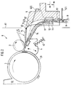
- FIG. 1 schematically shows a section of an open-end spinning device with an insertion funnel 1, a feed roller 2, a feed trough 4 and an opening roller 3 attached to it, which is located in an opening roller housing 31.
- a fiber feed channel 32 connects to the opening roller housing 31 and serves to convey the opened fibers to a spinning element, not shown, for example a rotor or a friction spinning device. Since these are well-known open-end spinning devices, a more detailed description is omitted here.
- the insertion funnel 1 is positively arranged in the feed trough 4, which can be moved concentrically about the axis of the opening roller, for example with a clip or dovetail closure. This connection can be made detachable.
- the feed trough 4 is pressed by a spring 42, on the one hand, against the outer wall of an opening roller housing 31 and, on the other hand, against the feed roller 2.
- the sliver 9 is passed through a channel 12 of the loop catcher 11 and then guided to the introduction funnel 1.
- the loop catcher 11 serves primarily to separate adhering second loops from the sliver 9, which is conveyed out of a sliver can, so that only the correct sliver cross-section can enter the spinning station.
- the cross section of the channel 12 is usually round-oval.
- the loop catcher 11 itself can be designed to be removable from the inlet funnel 1 and is expediently clipped into the foot part 13 of the inlet funnel 1 by means of a clip.
- the inlet funnel 1 has two walls 14 and 15, shown here in section, approaching in the direction of the clamping point of the feeding device, the greatest approximation of which is at a narrow point 16 which is closest to the clamping line of the clamping elements 2 and 4.
- the spring 42 which presses the feed trough 4 against the feed roller 2 and the opening roller housing 31, is supported in the housing of the spinning station. Only one spring 42 is shown in this example. Of course, several springs with different points of attack can also be provided. It is also possible to move the feed roller around a pivot point that is not in the axis of rotation of the opening roller.
- Figure 2 essentially shows the device described in Figure 1, but here is an injector 5, which is provided on the contact surface with the inlet funnel 1 with a seal, is placed on the inlet funnel 1 and is already moving in such a way that inlet funnel 1 and the associated one now move Feed trough 4 from the feed roller Have removed 2 so that the clamping line between these two clamping elements is open.
- the injector 5 was moved into this position by a movement in the direction of the arrow Z and placed on the insertion funnel 1.
- the feed trough 4 is pressed down and the clamping line is thus opened.
- the injector 5 is expediently articulated in such a way that it can follow a small rotational movement of the feed trough 4 without 5 leaks occurring between the insertion funnel 1 and the injector. If, after threading the sliver 9, the injector 5 is moved away from the spinning position in the direction of arrow E, the feed trough 4 and the insertion funnel 1 attached to it move up again due to the spring action of the spring 42. The feed trough 4 then presses the sliver against the stationary feed roller 2.
- the procedure for feeding a sliver 9 to a spinning station is carried out as follows:
- the injector 5 is turned on with a device (not shown), which is, for example, a ground vehicle traveling along the OE spinning machine, an automatic maintenance device arranged on the spinning machine, or another maintenance vehicle guided the spinning station and moved against the insertion funnel 1 in such a way that the feed trough 4 moves away from the feed roller 2.
- the injector 5 must be positioned on the inlet funnel 1, for example using the usual positioning methods that are customary for maintenance machines at spinning positions. Then one of them is not shown Device the injector 5 in the direction of arrow A at its insertion opening the beginning of the sliver 9 presented.
- the sliver channel 8 is formed in that the two parts of the device, insertion funnel 1 and injector 5, close together.
- the sliver 9 passes through the constriction 16, between the feed roller 2 and the feed trough 4, so that the beginning of the sliver is offered to the opening roller 3 for processing.
- a nozzle 51 can be fitted in the lower part of the injector 5.
- the nozzle 52 is expediently arranged such that it emits a flow which acts in the channel 12 of the loop catcher 11 in such a way that there is a slight vortex flow which twists the beginning of the sliver 9 in a manner such as how to end the thread with the fingers twisted together to sharpen it a bit and lead it through a constriction.
- the injector 5 from the insertion funnel 1, or from the spinning unit 6, preferably in the direction of arrow E. Because the injector on its underside in the area of Nozzle 52, pointing to the spinning machine, is open, it can be removed from the spinning position without hindrance without impairing the sliver 9. This recess at the foot of the injector is visible in the dashed line in FIG. 3, which is designated 58.
- FIG. 3 shows a top view of the injector 5, a line labeled 59, which shows the inner wall of the "channel half" of the channel 8, which is formed by joining the parts injector and insertion funnel.
- the symmetrical arrangement of the nozzle channel 522 and the nozzle 52 can also be seen in FIG.
- FIG. 4 shows nozzle channels 522a and 522b, or their nozzles 52a and 52b, the nozzle channels 522a and 522b preferably being aligned such that their lines of action intersect in the constriction 16 of the insertion funnel 1.
- the arrangement of a nozzle channel 511 and the nozzle 51 can also be seen here.
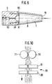
- Figure 5 shows the front view of the injector 5, it being very easy to see in the lower part that a sliver insertion opening 55 is formed such that it extends essentially conically upwards, so that its cross section at the transition point in the loop catcher 11 of the Insertion funnel 1 is approximately as large as the cross section of the channel 12 of the loop catcher.
- a wall 58 will pass into the wall of the channel 12 of the loop catcher 11 and in the further course of the channel 8 into a wall 59 of the injector 5.
- the transitions of the channel parts The insertion opening 55 of the injector 5, the channel 12 and the channel wall 59 should be designed to be as smooth and free of edges as possible so that there is no damage to the sliver 9 when the individual parts of the device are inserted or fly.
- FIG. 6 shows a further advantageous embodiment of the subject matter of the invention.
- An injector 5 is provided here, which has a further nozzle 53 which does not open directly into the sliver channel 8 like the other two nozzles 52 and 51, but into a nozzle channel 177 which is arranged in the upper wall 15 of the insertion funnel 1 and with a nozzle 178, which is located just before the nip between feed roller 2 and feed trough 4, opens.
- This third nozzle 53 is useful, for example, when processing sliver materials which, due to their weight or their friction behavior, cannot be inserted into the introduction funnel 1 so easily.
- the conveying air flow for the sliver 9 is supported in the direction of the clamping point of the spinning device, in that a vacuum is created at the constriction 16 by means of the air flowing through the nozzle 178, which causes the sliver 9 or the beginning of the sliver 9 moves more easily through the constriction 16 to the clamping point or between the clamping elements of the spinning device.
- nozzle in the wall 14 which can be acted upon by the injector 5 with compressed air.
- the feeding of the sliver 9 can also be supported by the fact that the sliver 9 is lifted so far from a device (for example from a spinning can) so that the device according to the invention only lifts the sliver length that is introduced into the spinning station got to.
- a device for example from a spinning can
- the above-described method and the various devices for this are of course applicable to all open-end spinning devices and are not limited to rotor spinning.
- the feed device can be designed, for example, as an apron drafting system.
- the spinning device can be a friction or air spinning device or, more generally, a spinning device that works with an open end or with fibers released.
- This sliver feed can also be used on other sliver processing machines such as Routes are provided, where it is useful to provide a feed device which is capable of further conveying the sliver itself for further processing after the feed device has presented and presented the sliver to the feed device.
- the feed devices for the nozzles 51, 52 and 53 or further arranged nozzles are supplied with compressed air via the feed lines shown.
- the control of the timing of the injector nozzle flows can be individually adjusted depending on the sliver.
- a control is expediently provided here, which it allows the nozzles and their switching sequence to be controlled after the operator has been freely selected.
- the device according to the invention is also expediently integrated into electronically controlled maintenance machines which check for the possible presence of another sliver before a new sliver is attached or before a sliver is introduced into a spinning station.
- a sliver can containing the sliver supply is already present at a spinning station, the sliver end to be inserted hanging out of the can at a certain position or has already been presented to a fixing point at the spinning station by means of a known device.
- a maintenance vehicle can remove an empty sliver can from the respective spinning station, bring a sliver containing sliver to the spinning station and then feed this sliver to the spinning device by means of the device according to the invention.
- the injector 5 or the control device (not shown) of the nozzles of the injector 5 are expediently set such that an injection process takes approximately 1 second. This is advantageous for the sliver, since not too long currents act on the sliver and change or damage it in such a way that it can no longer be conveyed without errors by the feed device.
- the nozzle 178 shown in FIG. 6 can of course also be used in cooperation with the nozzle 53 of the injector 5 to clean a possibly missed clamping point by means of a short air flow pulse before the sliver 9 of the insertion opening 55 for insertion is presented.
- a gripper is advantageously used which has two gripping elements, at least one of which is arranged so as to be movable, that the gripper can be opened and closed again for gripping the sliver.
- the two grippers are designed as rollers which rotate to support the insertion process in such a way that the sliver is conveyed in the direction of the spinning station. The conveying speed and the timing of the running of the rollers are expediently coordinated with the control unit controlling the nozzles.
- Figure 7 shows an injector 5 in longitudinal section.
- the arrangements of the nozzles 51 and 52 and a nozzle 62 are provided.
- Nozzle 51 is directed against the side wall of the sliver insertion opening 55 in such a way that an air vortex is created which twists and / or sharpens the sliver 9. It is thereby achieved that simple threading into the loop catcher 11 of the insertion funnel 1 is possible.
- nozzle 51 is connected to nozzle 62.
- Nozzle 62 supports due to the suction effect of threading the sliver 9 into the insertion funnel 1, which extends into the sliver insertion opening 55, the nozzle 52 can be controlled independently of this and can therefore be pressurized with compressed air after the nozzles 51 and 62. An optimal deflection of the sliver (9) in the direction of the narrow point (16) of the insertion funnel 1 is achieved.
- Rollers 70, 71 are arranged as an additional mechanical tape feed device in the sliver conveying direction directly in front of the injector 5. These rollers 70, 71 grip the fiber sliver 9 and convey it by a rotational movement in the direction of the injector 5. The gripping of the fiber sliver 9 is facilitated by conical ends 701 of the rollers 70, 71. The sliver 9 thus threads itself into the corrugated rolls 70, 71 when it comes into contact with the conical ends 701 of the rotating rolls 70, 71.
- the speed of rotation of the rollers 70, 71 is advantageously such that, compared to the conveying action of the nozzles 51, 52, 62, it slows down the conveyance of the sliver 9 slightly. It is thereby achieved that the sliver 9 is always conveyed in a taut state through the loop catcher 12 or the constriction 16 of the insertion funnel 1. This prevents the sliver 9 from clogging the channels 11, 16 to be traversed and thus would prevent a safe threading into the feeding device.
- the rollers 70, 71 ensure that a defined amount and thus also the weight of the sliver 9 is always conveyed. This is an adjustment of the nozzles 51, 52, 62 with respect to their Flow duration and intensity easier. A safe conveying of the sliver through the channels 11, 16 is thus ensured.
- a seal 63 is arranged on the upper edge of the injector 5. This seal 63 has the effect that a tight connection between injector 5 and inlet funnel 1 can be established. This prevents flow losses from occurring in the channels 8, 11.
- Figure 8 shows a front view of the injector 5 with the rollers 70, 71.
- the nozzle 51 is so inclined to the center line of the injector 5 that it generates an air vortex that prepares the sliver for threading into the narrow points.
- nozzle 51 causes by means of its air jet that the sliver 9 is conveyed in the direction of the nozzle 52.
- the nozzle 52 causes the fiber sliver 9 to be deflected in the direction of the constriction 16 of the insertion funnel 1.
- the fiber sliver 9 is guided at this deflection point through the wall 59 of the injector 5.
- nozzles 60, 61 are arranged on the front of the injector 5.
- the nozzles 60, 61 are also directed in the direction of the constriction 16 of the insertion funnel 1 and cause the sliver to be blown towards the constriction 16. Due to the additional use of the nozzles 60, 61, the flow velocity is maintained despite the changed cross-section, without turbulence or significant flow velocity losses occurring. This is advantageous achieved that the sliver is conveyed towards the narrow point 16 without forming swirls or loops. Clogging of the constriction 16 by the sliver is thus prevented.
- the nozzles 60, 61 ensure safe conveying of the sliver 9 up to the feeding device.
- the rollers 70, 71 rotate in the direction of the injector 5.
- the conveyance of the sliver 9 is mechanically supported by the air nozzles 51, 52, 60, 61.
- the rollers 70, 71 are operated at a speed such that the sliver 9 is always tightened during the pneumatic conveying. This means that the rollers 70, 71 convey more slowly than the air nozzles 51, 52, 60, 61 would do. Clogging of the constrictions by the sliver 9 is thus avoided.
- rollers 70, 71 are advantageously arranged on a maintenance device. Rollers 70, 71 and injector 5 are accordingly only fed to the spinning machine or the spinning station if sliver is to be conveyed through the narrow points and threaded into the spinning machine.
- the maintenance device can either be arranged directly on the spinning machine and can be moved, for example, along a large number of spinning stations, or independently of the individual spinning machine, for example on one or more spinning machines operating automated transport system can be arranged. It has proven to be advantageous to arrange the injector 5 and rollers 70, 71 on a can transporter and thus to introduce the new fiber sliver 9 into the spinning station when the can needs to be replaced at the spinning station.
- roller 70, 71 it is possible that the roller 70, 71 can be removed from one another (70 ') for gripping the fiber sliver 9 and can be brought together again. This ensures a secure and defined gripping of the sliver 9.
- FIG. 9 shows a section through a top view of the injector 5 and the insertion funnel 1.
- the sliver 9 which is deflected along the wall 59 from the injector 5 into the insertion funnel 1, would be swirled strongly without the support of the nozzles 60, 61 when entering the insertion funnel 1 and thus run the risk of narrowing 16 of the insertion funnel 1 to clog.
- the nozzles 60, 61 increase the flow velocity in the larger cross section of the insertion funnel 1 and thereby cause the sliver 9 to be tightened. In addition, they prevent excessive friction of the sliver 9 on the walls of the insertion funnel 1. This also ensures that the sliver is guided safely 9 guaranteed by the constriction 16 of the insertion funnel 1.
- the nozzles 60, 61 are preferably arranged such that they produce an air flow parallel to the side walls of the insertion funnel 1.
- An air cushion is formed which reduces the friction of the sliver 9 on the side walls.
- the nozzles 60, 61 can be dispensed with if the cross-sectional expansion between injector 5 and insertion funnel 1 is not very large. This can be achieved with a given insertion funnel 1 in that 5 side elements are attached to the injector, which are inserted into the channel 8 and thus reduce the cross section. It is also possible to design the injector 5 with its wall 59 or the injector 1 in such a way that there is no major change in cross-section.
- FIG. 10 shows a sliver separating device 80.
- a clamp 81 grips the sliver 9 on the side of the rollers 70, 71 facing the injector 5 and holds the sliver 9 firmly.
- a clamping device 82 also grips the sliver 9 and moves away from the clamping device 81 in the direction of the arrow after the clamping process.
- the sliver 9 is separated between the clamping device 81 and 82.
- the clamping device 81 detaches from the sliver 9. It is thus a defined length of the sliver 9 from the rollers 70, 71 to the beginning of the Sliver 9 made. This defined length ensures that the fiber sliver is securely inserted into the injector 5 or the insertion funnel 1.
- FIG. 11 shows an automatic maintenance machine 90 on a spinning machine 91.
- the automatic maintenance machine 90 runs on a rail along the spinning machine 91. If a fiber sliver 9 is inserted into the spinning station, the automatic walking machine 90 stops at this spinning station. The sliver is gripped and fed to the injector 5, which is arranged on the automatic hiking device 90. The sliver 9 is then inserted into the nip of the spinning station.
Abstract
Description
Die vorliegende Erfindung betrifft ein Verfahren und eine Vorrichtung zum pneumatischen Einführen von Faserband in eine Spinnereimaschine gemäß den Oberbegriffen der Ansprüche 1 und 7.The present invention relates to a method and a device for the pneumatic introduction of sliver into a spinning machine according to the preambles of
Es ist aus der EP 0 348 678 A1 eine Vorrichtung und ein Verfahren bekannt, mit denen das Faserband in eine Spinnvorrichtung pneumatisch eingeführt wird. Die dort gezeigte Vorrichtung ist mit einem Verdichter versehen. Dieser Verdichter ist an einer Spinnstelle ortsfest installiert vorgesehen und wird, nachdem ihm an einer rohrförmigen Faserbandansaugöffnung Faserband angeboten wird, mit einem Luftstrom, den eine zuvor angedockte Injektordüse abgibt, derart beaufschlagt, daß das Faserband in Richtung der engsten Stelle des Verdichters strömen bzw. gefördert werden soll.A device and a method are known from EP 0 348 678 A1 with which the fiber sliver is pneumatically introduced into a spinning device. The device shown there is provided with a compressor. This compressor is provided to be installed in a fixed position at a spinning station and, after being offered with sliver at a tubular sliver suction opening, is acted upon by an air stream which is emitted by a previously docked injector nozzle in such a way that the sliver flows or is conveyed in the direction of the narrowest point of the compressor shall be.
Nachteilig bei dieser bekannten Vorrichtung ist, daß auf das Faserband in der rohrförmigen Ansaugöffnung aufgrund der benötigten Querschnitte eine relativ geringe Saugkraft wirkt. Andererseits besteht an der engsten Stelle des Verdichters die Gefahr, daß durch den Luftdruck, der auf das Faserband einwirkt der Verdichter durch das Faserband verstopft wird und damit nicht in jedem Fall sichergestellt wird, daß das Faserband aus dem Verdichter so weit austritt, daß es dort von weiteren Vorrichtungen ergriffen wird und weiter gefördert werden kann.A disadvantage of this known device is that a relatively low suction force acts on the fiber sliver in the tubular suction opening due to the required cross sections. On the other hand, at the narrowest point of the compressor, there is a risk that the air pressure acting on the sliver clogs the compressor by the sliver and thus does not always ensure that the sliver exits the compressor to the extent that it is there seized by other devices will and can be further promoted.
Aufgabe der vorliegenden Erfindung ist es nun, die oben geschilderten Nachteile zu überwinden und ein Verfahren und eine Vorrichtung zu schaffen, die es ermöglichen, das Zuführen von Faserband in eine Spinnereimaschine einfach und sicher zu gestalten.The object of the present invention is now to overcome the disadvantages described above and to provide a method and an apparatus which make it possible to make the feeding of sliver into a spinning machine simple and safe.
Die Aufgabe wird durch die Merkmale der Ansprüche 1, 7 und 11 gelöst.The object is achieved by the features of
Weitere vorteilhafte Ausbildungen der Erfindung sind in den Unteransprüchen beschrieben.Further advantageous developments of the invention are described in the subclaims.
Um das Wesen der Erfindung deutlich zu machen, werden im folgenden anhand einer Figurenbeschreibung vorteilhafte Ausbildungen des Erfindungsgegenstandes beschrieben.In order to make the essence of the invention clear, advantageous embodiments of the subject matter of the invention are described below with the aid of a description of the figures.
Es zeigt
Figur 1 eine Schemazeichnung einer Spinnstelle im Schnitt vor dem Öffnen der Klemmstelle der Zuspeisevorrichtung;Figur 2 schematisiert im Querschnitt die Spinnvorrichtung nach dem Ansetzen eines Injektors an die Zuspeisevorrichtung;- Figuren 3 und 4 eine Draufsicht auf jeweils eine Injektor mit unterschiedlicher Anordnung von Druckluftdüsen;
Figur 5 eine Vorderansicht des Injektors mit Blick in die Injektoröffnung;- Figur 6 eine weitere Ausbildung des Einführtrichters im Schnitt.
- Figur 7 einen Schnitt durch einen Injektor.
Figur 8 eine Vorderansicht eines Injektors.Figur 9 einen Querschnitt durch einen Injektor und einen Einführtrichter.- Figur 10 eine Faserbandtrennvorrichtung.
Figur 11 einen Wartungsautomat an einer Spinnmaschine
- Figure 1 is a schematic drawing of a spinning station in section before opening the clamping point of the feeding device;
- Figure 2 schematically shows in cross section the spinning device after attaching an injector to the feeding device;
- Figures 3 and 4 is a plan view of an injector with a different arrangement of compressed air nozzles;
- Figure 5 is a front view of the injector looking into the injector opening;
- Figure 6 shows another embodiment of the insertion funnel in section.
- 7 shows a section through an injector.
- Figure 8 is a front view of an injector.
- Figure 9 shows a cross section through an injector and an insertion funnel.
- Figure 10 shows a sliver cutting device.
- Figure 11 shows a maintenance machine on a spinning machine
Figur 1 zeigt schematisch einen Ausschnitt einer Offenend-Spinnvorrichtung mit einem Einführtrichter 1, einer Speisewalze 2, einer Speisemulde 4 und einer daran angegliederten Auflösewalze 3, die sich in einem Auflösewalzengehäuse 31 befindet. An das Auflösewalzengehäuse 31 schließt sich ein Faserspeisekanal 32 an, der dazu dient, die aufgelösten Fasern zu einem nichtgezeigten Spinnelement z.B. einem Rotor oder einer Friktionsspinnvorrichtung zu fördern. Da es sich hierbei um hinreichend bekannte Offenend-Spinnvorrichtungen handelt, wird hier auf eine detailliertere Beschreibung verzichtet. Der Einführtrichter 1 ist in die Speisemulde 4, die sich konzentrisch um die Achse der Auflösewalze bewegen läßt, beispielsweise mit einem Klips- oder Schwalbenschwanzverschluß formschlüssig angeordnet. Diese Verbindung kann lösbar ausgebildet sein. Die Speisemulde 4 wird durch eine Feder 42 einerseits gegen die Außenwand eines Auflösewalzengehäuses 31 gedrückt und andererseits gegen die Speisewalze 2. Der Einführtrichter 1 ragt mit seinem angegliederten Schlingenfänger 11 aus der Spinnvorrichtung, deren Begrenzung mit der Linie 61 dargestellt sein soll, heraus. Diese Begrenzungslinie 61 markiert zugleich die Außenkante der Offenend-Spinnmaschine. Durch einen Kanal 12 des Schlingenfängers 11 wird das Faserband 9 hindurchgeleitet und dann zum Einführungstrichter 1 geführt. Der Schlingenfänger 11 dient in erster Linie dazu, am Faserband 9, das aus einer Faserbandkanne herausgefördert wird, anhaftende Zweitschlingen von Band zu trennen, so daß nur der richtige Faserbandquerschnitt in die Spinnstelle einlaufen kann. Üblicherweise ist der Querschnitt des Kanals 12 rund-oval ausgebildet. Der Schlingenfänger 11 selbst kann vom Einlauftrichter 1 abnehmbar gestaltet sein und wird zweckmäßigerweise über einen Klips in das Fußteil 13 des Einlauftrichters 1 eingeklipst. Der Einlauftrichter 1 hat zwei, hier im Schnitt dargestellte, sich in Richtung zur Klemmstelle der Zuspeisevorrichtung annähernde Wandungen 14 und 15 deren größte Annäherung sich an einer Engstelle 16, die der Klemmlinie der Klemmelemente 2 und 4 am nächsten liegt, befindet. Die Feder 42, die die Speisemulde 4 gegen die Speisewalze 2 und das Auflösewalzengehäuse 31 drückt, stützt sich im Gehäuse der Spinnstelle ab. Es ist in diesem Beispiel nur eine Feder 42 gezeigt. Es können natürlich auch mehrere, verschiedene Angriffspunkte aufweisende Federn vorgesehen werden. Es ist ebenso möglich die Speisewalze um einen Drehpunkt zu bewegen, der nicht in der Drehachse der Auflösewalze liegt.FIG. 1 schematically shows a section of an open-end spinning device with an
Figur 2 zeigt im wesentlichen die in Figur 1 beschriebene Vorrichtung jedoch ist hier ein Injektor 5, der an der Kontaktfläche mit dem Einlauftrichter 1 mit einer Dichtung versehen ist, an den Einlauftrichter 1 angelegt und schon so bewegt, daß sich nun Einlauftrichter 1 und die angegliederte Speisemulde 4 von der Speisewalze 2 entfernt haben, so daß die Klemmlinie zwischen diesen beiden Klemmelementen offen ist. Der Injektor 5 wurde in diese Stellung durch eine Bewegung in Richtung des Pfeiles Z bewegt und an den Einführtrichter 1 angelegt. Durch das Andrücken einer Anlauffläche 57 an eine Anlauffläche 17 des Einlauftrichters 1 aufgrund der Bewegung des Injektors 5 in Richtung des Pfeiles Z wird die Speisemulde 4 nach unten gedrückt und damit die Klemmlinie geöffnet. Zweckmäßigerweise ist der Injektor 5 derart gelenkig gelagert, daß er einer kleinen Drehbewegung der Speisemulde 4 folgen kann, ohne daß zwischen Einführtrichter 1 und Injektor 5 Undichtigheiten entstehen können. Wird nach dem Einfädeln des Faserbandes 9 der Injektor 5 in der Richtung des Pfeiles E von der Spinnstelle wegbewegt, so bewegen sich aufgrund der Federwirkung der Feder 42 die Speisemulde 4 und der daran angegliederte Einführtrichter 1 wieder nach oben. Die Speisemulde 4 drückt dann das Faserband gegen die ortsfest angebrachte Speisewalze 2.Figure 2 essentially shows the device described in Figure 1, but here is an
Zum Durchführen des Verfahrens zum Zuführen eines Faserbandes 9 an eine Spinnstelle wird folgendermaßen vorgegangen: Der Injektor 5 wird mit einer nicht gezeigten Vorrichtung, welche z.B. ein an der OE-Spinnmaschine entlangfahrendes Bodenfahrzeug, ein an der Spinnmaschine angeordneter Wartungsautomat oder ein sonstiges Wartungsfahrzeug ist, an die Spinnstelle geführt und gegen den Einführtrichter 1 derart bewegt, daß die Speisemulde 4 sich von der Speisewalze 2 entfernt. Hierbei ist das Positionieren des Injektors 5 am Einlauftrichter 1, beispielsweise mit den üblichen Positionierverfahren wie sie für Wartungsautomaten an Spinnstellen üblich sind, durchzuführen. Sodann wird von einer nicht gezeigten Vorrichtung dem Injektor 5 in Richtung des Pfeiles A an seiner Einführöffnung der Beginn des Faserbandes 9 dargeboten. Aufgrund der Saugwirkung eines Luftstromes, der über eine Leitung 522 von einer Druckluftquelle über eine Düse 52 in einen Faserbandkanal 8 gerichtet ist, wird das Faserband in den Faserbandkanal 8 und weiter in Richtung einer Wirkungslinie 523 des Luftstromes, der aus der Düse 52 strömt, gefördert. Der Faserbandkanal 8 wird dadurch gebildet, daß die beiden Vorrichtungsteile, Einführtrichter 1 und Injektor 5, dicht miteinander abschließen. Das Faserband 9 passiert durch die Engstelle 16 hindurch, zwischen die Speisewalze 2 und die Speisemulde 4, so daß der Beginn des Faserbandes der Auflösewalze 3 zur Bearbeitung dargeboten wird. Im unteren Teil des Injektors 5 kann eine Düse 51 angebracht sein. Sie wird zur Unterstützung des Injektionsvorganges vorzugsweise mit einem geringen zeitlichen Vorlauf derart aktiviert, daß eine im wesentlichen senkrechte Saugströmung im Kanal 8 injiziert wird, und dadurch das Faserband 9 nach oben bewegt wird. Die zusätzliche, schon oben geschilderte Aktion der Düse 52 wird dann die Richtungsumlenkung und zusätzliche Förderung des Faserbandes 9 übernehmen. Die Düse 52 ist zweckmäßigerweise so angeordnet, daß sie eine Strömung abgibt, die im Kanal 12 des Schlingenfängers 11 derart wirkt, daß dort eine leichte Wirbelströmung entsteht, die den Beginn des Faserbandes 9 zusammendreht, in einer Weise, wie man ein Fadenende mit den Fingern zusammendreht, um es etwas anzuspitzen und es durch eine Engstelle hindurchzuführen. Ist nun das Faserband 9 bis an die Klemmstelle kurz vor der Auflösewalze 3 gefördert worden, wird mit einer (nicht gezeigten) Serviceeinrichtung (diese kann auch durch eine Bedienungsperson dargestellt sein), der Injektor 5 vom Einführtrichter 1, bzw. von der Spinneinheit 6 entfernt und zwar vorzugsweise in Richtung des Pfeiles E. Dadurch, daß der Injektor an seiner Unterseite im Bereich der Düse 52, zur Spinnmaschine zeigend, offen ist, kann er ungehindert von der Spinnstelle entfernt werden, ohne das Faserband 9 zu beeinträchtigen. Diese Aussparung am Fuße des Injektors ist sichtbar in der gestrichelten Linie in der Figur 3, die mit 58 bezeichnet ist.The procedure for feeding a
Die Figur 3 zeigt in einer Draufsicht des Injektors 5 eine mit 59 bezeichnete Linie, die die Innenwandung der "Kanalhälfte" des Kanals 8, der durch Zusammenfügen der Teile Injektor und Einführtrichter gebildet wird. Es ist in Figur 3 auch die symmetrische Anordnung des Düsenkanals 522 und die Düse 52 zu erkennen. Im Gegensatz dazu zeigt die Figur 4 Düsenkanäle 522a und 522b, bzw. deren Düsen 52a und 52b, wobei die Düsenkanäle 522a und 522b vorzugsweise so ausgerichtet sind, daß sich ihre Wirkungslinien in der Engstelle 16 des Einführtrichters 1 schneiden. Es ist hier desweiteren auch die Anordnung eines Düsenkanals 511 und der Düse 51 zu erkennen.FIG. 3 shows a top view of the
Figur 5 zeigt die Vorderansicht des Injektors 5, wobei im unteren Teil sehr gut zu erkennen ist, daß eine Faserbandeinführöffnung 55 derart ausgebildet ist, daß sie sich nach oben hin im wesentlichen konisch erstreckt, so daß ihr Querschnitt an der Übergangsstelle in den Schlingenfänger 11 des Einführtrichters 1 ungefähr so groß ist wie der Querschnitt des Kanals 12 des Schlingenfängers. Es wird also bei ordnungsgemäßem Ansetzen des Injektors 5 an den Einführtrichter 1 bzw. dessen Schlingenfänger 11 eine Wandung 58 in die Wandung des Kanals 12 des Schlingenfängers 11 übergehen und im weiteren Verlauf des Kanales 8 in eine Wandung 59 des Injektors 5. Die Übergänge der Kanalteile Einführöffnung 55 des Injektors 5, Kanal 12 und Kanalwandung 59 sollen möglichst kantenfrei und glatt gestaltet sein, so daß es nicht zu Schädigungen des Faserbandes 9 beim Einführen oder einer Verflugung der einzelnen Vorrichtungsteile kommt.Figure 5 shows the front view of the
Figur 6 zeigt eine weitere vorteilhafte Ausbildung des Erfindungsgegenstandes. Es ist hier ein Injektor 5 vorgesehen, der eine weitere Düse 53 aufweist, die nicht wie die beiden anderen Düsen 52 und 51 direkt in den Faserbandkanal 8 mündet, sondern in einen Düsenkanal 177, der in der oberen Wandung 15 des Einführtrichters 1 angeordnet ist und mit einer Düse 178, die kurz vor der Klemmstelle zwischen Speisewalze 2 und Speisemulde 4 liegt, mündet. Diese dritte Düse 53 ist beispielsweise dann sinnvoll, wenn Faserbandmaterialien verarbeitet werden, die sich aufgrund ihres Gewichtes oder ihres Reibungsverhaltens nicht so einfach in den Einführungstrichter 1 einführen lassen. Für diesen Fall wird der Förderluftstrom für das Faserband 9 in Richtung der Klemmstelle der Spinnvorrichtung unterstützt, dadurch daß mittels der durch die Düse 178 strömenden Luft an der Engstelle 16 ein Unterdruck geschaffen wird, der bewirkt, daß das Faserband 9 bzw. der Beginn des Faserbandes 9 sich leichter durch die Engstelle 16 zur Klemmstelle, bzw. zwischen die Klemmelemente der Spinnvorrichtung bewegt. In ähnlicher Weise kann man sich eine zusätzlich angebrachte Düse in der Wandung 14 vorstellen, die entsprechend vom Injektor 5 mit Druckluft beaufschlagt werden kann.Figure 6 shows a further advantageous embodiment of the subject matter of the invention. An
In vorteilhafter Weise kann das Zuführen des Faserbandes 9 auch dadurch unterstützt werden, daß von einer Vorrichtung das Faserband 9 noch so weit (aus beispielsweise einer Spinnkanne) hochgehoben wird, so daß die erfindungsgemäße Vorrichtung nur die Faserbandlänge, die in die Spinnstelle eingeführt wird, heben muß.Advantageously, the feeding of the
Das vorbeschriebene Verfahren und die verschiedenen Vorrichtungen dazu sind natürlich auf sämtliche Offenend-Spinnvorrichtungen anwendbar und nicht auf das Rotorspinnen beschränkt. Die Zuspeisevorrichtung kann beispielsweise als Riemchenstreckwerk ausgebildet sein. Ebenso kann die Spinnvorrichtung eine Friktions- oder Luftspinnvorrichtung oder ganz allgemein eine Spinnvorrichtung sein, die mit offenem Ende bzw. mit aufgelösten Fasern arbeitet.The above-described method and the various devices for this are of course applicable to all open-end spinning devices and are not limited to rotor spinning. The feed device can be designed, for example, as an apron drafting system. Likewise, the spinning device can be a friction or air spinning device or, more generally, a spinning device that works with an open end or with fibers released.
Diese Faserbandzuführung kann auch an anderen faserbandverarbeitenden Maschinen wie z.B. Strecken vorgesehen werden, wobei es sinnvoll ist, hier jeweils eine Zuspeiseeinrichtung vorzusehen, die im Stande ist, selbst das Faserband zur Weiterverarbeitung weiter zu befördern, nachdem die Zuführvorrichtung das Faserband der Zuspeisevorrichtung dargeboten und vorgelegt hat.This sliver feed can also be used on other sliver processing machines such as Routes are provided, where it is useful to provide a feed device which is capable of further conveying the sliver itself for further processing after the feed device has presented and presented the sliver to the feed device.
Die Zuführvorrichtungen für die Düsen 51, 52 und 53 bzw. weitere angeordnete Düsen werden über die gezeigten Zuleitungen mit Druckluft versorgt. Die Steuerung des zeitlichen Ablaufs der Injektordüsenströmungen ist je nach Faserband individuell einstellbar. Zweckmäßigerweise ist hier eine Steuerung vorgesehen, die es erlaubt, nach freier Auswahl des Bedieners die Düsen und deren Schaltreihenfolge zu steuern. Sinnvollerweise wird die erfindungsgemäße Vorrichtung auch in elektronisch gesteuerte Wartungsautomaten integriert, die vor dem Ansetzen eines neuen Faserbandes, bzw. vor dem Einführen eines Faserbandes in eine Spinnstelle das etwaige Vorhandensein eines anderen Faserbandes prüfen. Es ist denkbar, daß eine den Faserbandvorrat enthaltene Spinnkanne bereits an einer Spinnstelle vorhanden ist, wobei das einzuführende Faserbandende an einer bestimmten Position aus der Kanne heraushängt oder auch schon mittels einer bekannten Vorrichtung an eine Festlegestelle an der Spinnstelle vorgelegt wurde. Desweiteren kann ein Wartungsfahrzeug eine leere Spinnkanne von der jeweiligen Spinnstelle entfernen, eine Faserband enthaltende Kanne an die Spinnstelle bringen und dann dieses Faserband mittels der erfindungsgemäßen Vorrichtung der Spinnvorrichtung zuführen.The feed devices for the
Der Injektor 5 bzw. die (nicht gezeigte) Steuereinrichtung der Düsen des Injektors 5 werden zweckmäßigerweise so eingestellt, daß ein Injektionsvorgang ungefähr 1 Sekunde lang dauert. Dies ist insofern für das Faserband günstig, als nicht allzulange Strömungen auf das Faserband wirken und es derart verändern, bzw. schädigen, so daß es nicht mehr fehlerfrei von der Zuspeisevorrichtung gefördert werden kann.The
Die in Figur 6 gezeigte Düse 178 kann im Zusammenwirken mit der Düse 53 des Injektors 5 natürlich auch dazu benützt werden, eine evtl. verflugte Klemmstelle mittels eines kurzen Luftstromstoßes zu reinigen, bevor das Faserband 9 der Einführöffnung 55 zum Einführen dargeboten wird.The
Es ist auch denkbar, die Bewegung von Einführtrichter und Injektor derart vorzunehmen, daß sie um eine Drehachse erfolgt, die im wesentlichen quer zur Längsachse der OE-Spinnmaschine liegt. Die Ausführung der erfindungsgemäßen Vorrichtung ist nicht auf die gezeigten Beispiele beschränkt.It is also conceivable to carry out the movement of the insertion funnel and injector in such a way that it takes place about an axis of rotation which is essentially transverse to the longitudinal axis of the OE spinning machine. The design of the device according to the invention is not restricted to the examples shown.
Zum Darbieten des Faserbandes 9 am Fuß des Injektors 5, um es in Richtung des Pfeiles A in die Spinnstelle zu injizieren, hat es sich gezeigt, daß vorteilhafterweise ein Greifer eingesetzt wird, der zwei Greifelemente aufweist, von denen mindestens eines derart beweglich angeordnet ist, daß der Greifer geöffnet und zum Greifen des Faserbandes wieder geschlossen werden kann. In weiterer Ausgestaltung der Erfindung werden die beiden Greifer als Walzen ausgebildet, die sich zur Unterstützung des Einführvorganges derart drehen, daß das Faserband in Richtung der Spinnstelle befördert wird. Die Fördergeschwindigkeit und der Zeitpunkt des Laufes der Walzen werden zweckmäßigerweise mit der die Düsen steuernden Steuerung abgestimmt.In order to present the
Figur 7 zeigt einen Injektor 5 im Längsschnitt. In diesem Schnitt sind die Anordnungen der Düsen 51 und 52 sowie eine Düse 62 dar gestellt. Düse 51 ist dabei derart gegen die Seitenwand der Faserbandeinführöffnung 55 gerichtet, daß ein Luftwirbel entsteht, welcher das Faserband 9 zusammendreht und/oder anspitzt. Dadurch wird erreicht, daß ein einfaches Einfädeln in den Schlingenfänger 11 des Einführtrichters 1 möglich ist. Düse 51 ist in diesem Ausführungsbeispiel mit der Düse 62 verbunden. Düse 62 unterstützt durch ihre bis in die Faserbandeinführöffnung 55 reichende Sogwirkung des Einfädeln des Faserbandes 9 in den Einführtrichter 1. Düse 52 ist davon unabhängig ansteuerbar und kann daher zeitlich den Düsen 51 und 62 nachfolgend mit Druckluft beaufschlagt werden. Damit wird ein optimales Umlenken des Faserbandes (9) in Richtung der Engstelle (16) des Einführtrichters 1 erreicht.Figure 7 shows an
In Faserbandförderrichtung unmittelbar vor dem Injektor 5 sind Walzen 70, 71 als zusätzliche mechanische Bandzuführvorrichtung angeordnet. Diese Walzen 70, 71 erfassen das Faserband 9 und fördern es durch eine Drehbewegung in Richtung des Injektors 5. Das Ergreifen des Faserbandes 9 wird durch konische Enden 701 der Walzen 70, 71 erleichtert. Das Faserband 9 fädelt sich damit selbständig in die geriffelten Walzen 70, 71 ein, wenn es in Kontakt mit den konischen Enden 701 der sich drehenden Walzen 70, 71 gelangt.
Die Drehgeschwindigkeit der Walzen 70, 71 ist vorteilhafterweise derart, daß es im Vergleich zu der Förderwirkung der Düsen 51, 52, 62 die Förderung des Faserbandes 9 geringfügig bremst. Dadurch wird erzielt, daß das Faserband 9 stets in gestrafftem Zustand durch den Schlingenfänger 12 bzw. die Engstelle 16 des Einführtrichters 1 gefördert wird. Damit wird vermieden, daß das Faserband 9 die zu durchlaufenden Kanäle 11, 16 verstopft und somit ein sicheres Einfädeln in die Zuspeisevorrichtung verhindern würde. Außerdem bewirken die Walzen 70, 71, daß stets eine definierte Menge und somit auch Gewicht des Faserbandes 9 gefördert wird. Damit wird eine Einstellung der Düsen 51, 52, 62 hinsichtlich ihrer Strömungsdauer und Intensität erleichtert. Ein sicheres Fördern des Faserbandes durch die Kanäle 11, 16 wird somit gewährleistet.The speed of rotation of the
Am oberen Rand des Injektors 5 ist eine Dichtung 63 angeordnet. Diese Dichtung 63 bewirkt, daß eine dichte Verbindung zwischen Injektor 5 und Einlauftrichter 1 hergestellt werden kann. Damit wird vermieden, daß in den Kanälen 8, 11 Strömungsverluste auftreten.A
Figur 8 zeigt eine Vorderansicht des Injektors 5 mit den Walzen 70, 71. Die Düse 51 ist dabei derart geneigt zur Mittellinie des Injektors 5 angeordnet, daß sie einen Luftwirbel erzeugt, der das Faserband zum Einfädeln in die Engstellen vorbereitet. Zusätzlich bewirkt Düse 51 mittels ihres Luftstrahls, daß das Faserband 9 in Richtung der Düse 52 gefördert wird. Die Düse 52 bewirkt, daß das Faserband 9 in Richtung der Engstelle 16 des Einführtrichters 1 umgelenkt wird. Geführt wird das Faserband 9 an dieser Umlenkstelle durch die Wandung 59 des Injektors 5. Zur Überbrückung der Querschnittsänderung zwischen der Wandung 59 und dem Einführtrichter 1 sind Düsen 60, 61 an der Vorderseite des Injektors 5 angeordnet. Die Düsen 60, 61 sind ebenfalls in Richtung auf die Engstelle 16 des Einführtrichters 1 gerichtet und bewirken, daß das Faserband gestrafft auf die Engstelle 16 hingeblasen wird. Durch den zusätzlichen Einsatz der Düsen 60, 61 wird die Strömungsgeschwindigkeit trotz des veränderten Querschnitts aufrechterhalten, ohne daß Verwirbelungen oder wesentliche Strömungsgeschwindigkeitsverluste auftreten. Hierdurch wird vorteilhafterweise erreicht, daß das Faserband ohne Verwirbelungen oder Schlaufen zu bilden in Richtung auf die Engstelle 16 befördert wird. Ein Verstopfen der Engstelle 16 durch das Faserband wird somit verhindert. Durch die Düsen 60, 61 wird eine sichere Förderung des Faserbandes 9 bis hin zu der Zuspeisevorrichtung gewährleistet.Figure 8 shows a front view of the
Die Walzen 70, 71 drehen sich in Richtung auf den Injektor 5. Damit wird die Förderung des Faserbandes 9 durch die Luftdüsen 51, 52, 60, 61 mechanisch unterstützt. In Abhängigkeit von den Größenverhältnissen Faserband zu Durchtrittsquerschnitten ist es insbesondere bei engen Durchtrittsquerschnitten und dickem Faserband vorteilhaft, wenn die Walzen 70, 71 mit einer Geschwindigkeit betrieben werden, daß das Faserband 9 während der pneumatischen Förderung stets gestrafft ist. Dies bedeutet, daß die Walzen 70, 71 langsamer fördern, als die Luftdüsen 51, 52, 60, 61 dies tun würden. Damit wird ein Verstopfen der Engstellen durch das Faserband 9 vermieden.The
Die Walzen 70, 71 sind vorteilhafterweise ebenso wie der Injektor 5 an einer Wartungsvorrichtung angeordnet. Walzen 70, 71 und Injektor 5 werden demnach nur der Spinnereimaschine bzw. der Spinnstelle zugestellt, wenn Faserband durch die Engstellen gefördert und in die Spinnereimaschine eingefädelt werden soll. Die Wartungseinrichtung kann entweder dirket an der Spinnereimaschine angeordnet sein und beispielsweise entlang einer Vielzahl von Spinnstellen verfahrbar sein, oder unabhängig von der einzelnen Spinnereimaschine beispielsweise auf einem mehrere Spinnereimaschinen bedienenden fahrlosen Transportsystem angeordnet sein. Als vorteilhaft hat sich erwiesen Injektor 5 und Walzen 70, 71 auf einem Kannentransporter anzuordnen und damit bei einem notwendig gewordenen Kannenwechsel an der Spinnstelle das neue Faserband 9 in die Spinnstelle einzuführen.The
In einer vorteilhaften Ausgestaltung der Anordnung der Walze 70, 71 ist es möglich, daß die Walze 70, 71 zum Ergreifen des Faserbandes 9 voneinander entfernbar (70') sind und wieder zusammenführbar sind. Damit wird ein sicheres und definiertes Ergreifen des Faserbandes 9 gewährleistet.In an advantageous embodiment of the arrangement of the
Figur 9 zeigt einen Schnitt durch eine Draufsicht des Injektors 5 und des Einführtrichters 1. In dieser Darstellung ist die Querschnittsvergrößerung beim Übergang zwischen dem Injektor 5 und dem Einführtrichter 1 deutlich erkennbar. Das Faserband 9, das entlang der Wandung 59 aus dem Injektor 5 in den Einführtrichter 1 umgelenkt wird, würde ohne Unterstützung durch die Düsen 60, 61 beim Eintritt in den Einführtrichter 1 stark verwirbelt werden und somit Gefahr laufen, in der Engstelle 16 des Einführtrichters 1 zu verstopfen. Die Düsen 60, 61 dagegen erhöhen die Strömungsgeschwindigkeit in dem größeren Querschnitt des Einführtrichters 1 und bewirken dadurch eine Straffung des Faserbandes 9. Außerdem verhindern sie eine zu große Reibung des Faserbandes 9 an den Wandungen des Einführtrichters 1. Auch dadurch wird ein sicheres Durchführen des Faserbandes 9 durch die Engstelle 16 des Einführtrichters 1 gewährleistet.FIG. 9 shows a section through a top view of the
Als vorteilhaft hat sich erwiesen, zuerst durch die Düsen 60, 61 eine Luftströmung zu erzeugen bis das Faserband 9 in ihrem Wirkungsbereich ist und anschließend erst die Düse 52 mit Druckluft zu beaufschlagen, damit das Faserband 9 durch die Engstelle 16 geblasen wird.It has proven to be advantageous, first through the
Vorzugsweise sind die Düsen 60, 61 derart angeordnet, daß sie eine Luftströmung parallel zu den Seitenwänden des Einführtrichters 1 erzeugen. Es wird dabei ein Luftpolster gebildet, das die Reibung des Faserbandes 9 an den Seitenwänden verringert.The
Auf die Düsen 60, 61 kann verzichtet werden, wenn die Querschnittserweiterung zwischen Injektor 5 und Einführtrichter 1 nicht sehr groß ist. Dies kann bei einem vorgegeben Einführtrichter 1 dadurch erzielt werden, daß an dem Injektor 5 Seitenelemente angebracht sind, welche in den Kanal 8 eingeführt werden und damit den Querschnitt verringern. Ebenso ist es möglich den Injektor 5 mit seiner Wandung 59 oder den Injektor 1 bereits derart zu gestalten, daß keine große Querschnittsveränderung stattfindet.The
Figur 10 zeigt eine Faserbandtrennvorrichtung 80. Eine Klemme 81 greift dabei das Faserband 9 an der dem Injektor 5 zugewandten Seite der Walzen 70, 71 und hält das Faserband 9 fest. Eine Klemmeinrichtung 82 greift ebenfalls das Faserband 9 und bewegt sich nach dem Klemmvorgang in Pfeilrichtung von der Klemmeinrichtung 81 weg. Dabei wird das Faserband 9 zwischen der Klemmeinrichtung 81 und 82 getrennt. Anschließend löst sich die Klemmeinrichtung 81 von dem Faserband 9. Es ist somit eine definierte Länge des Faserbandes 9 von den Walzen 70, 71 bis zum Beginn des Faserbandes 9 hergestellt. Durch diese definierte Länge wird ein sicheres Einführen des Faserbandes in den Injektor 5 bzw. den Einführtrichter 1 gewährleistet.FIG. 10 shows a
Figur 11 zeigt einen Wartungsautomat 90 an einer Spinnmaschine 91. Der Wartungsautomat 90 fährt auf einer Schiene entlang der Spinnmaschine 91. Ist ein Faserband 9 in die Spinnstelle einzuführen, stoppt der Wanderautomat 90 an dieser Spinnstelle. Das Faserband wird ergriffen und dem Injektor 5, der am Wanderautomaten 90 angeordnet ist, zugeführt. Das Faserband 9 wird sodann in die Klemmstelle der Spinnstelle eingeführt.FIG. 11 shows an
Die Erfindung ist nicht auf die beschriebenen Ausführungsbeispiele beschränkt.The invention is not restricted to the exemplary embodiments described.
Claims (24)
Applications Claiming Priority (4)
| Application Number | Priority Date | Filing Date | Title |
|---|---|---|---|
| DE19914126552 DE4126552C2 (en) | 1991-08-10 | 1991-08-10 | Method and device for the pneumatic introduction of sliver into an OE spinning machine |
| DE4126552 | 1991-08-10 | ||
| DE19914130510 DE4130510A1 (en) | 1991-09-13 | 1991-09-13 | Spinning station sliver insertion |
| DE4130510 | 1991-09-13 |
Publications (2)
| Publication Number | Publication Date |
|---|---|
| EP0527355A1 true EP0527355A1 (en) | 1993-02-17 |
| EP0527355B1 EP0527355B1 (en) | 1998-04-01 |
Family
ID=25906261
Family Applications (1)
| Application Number | Title | Priority Date | Filing Date |
|---|---|---|---|
| EP92112303A Expired - Lifetime EP0527355B1 (en) | 1991-08-10 | 1992-07-18 | Method and apparatus for pneumatically inserting sliver in a spinning machine |
Country Status (7)
| Country | Link |
|---|---|
| US (1) | US5343686A (en) |
| EP (1) | EP0527355B1 (en) |
| JP (1) | JPH05195338A (en) |
| BR (1) | BR9203046A (en) |
| CZ (1) | CZ284254B6 (en) |
| DE (1) | DE59209258D1 (en) |
| RU (1) | RU2072401C1 (en) |
Cited By (1)
| Publication number | Priority date | Publication date | Assignee | Title |
|---|---|---|---|---|
| EP3441509B1 (en) * | 2017-08-11 | 2021-07-21 | Saurer Spinning Solutions GmbH & Co. KG | Feed table for a sliver opening device of an open-end spinning device |
Families Citing this family (10)
| Publication number | Priority date | Publication date | Assignee | Title |
|---|---|---|---|---|
| CZ29294A3 (en) * | 1994-02-10 | 1995-10-18 | Rieter Deutschland Gmbh | Method of spinning yarn on spindleless spinning machines and apparatus for making the same |
| DE4428580A1 (en) * | 1994-08-12 | 1996-02-15 | Schlafhorst & Co W | Open end spinner cleaning |
| DE102008004098A1 (en) * | 2007-06-29 | 2009-01-02 | TRüTZSCHLER GMBH & CO. KG | Device for fiber sorting or selection of a fiber structure of textile fibers, in particular for combing, which is fed via feeding means of a fiber sorting device, in particular combing device |
| GB0811191D0 (en) * | 2007-06-29 | 2008-07-23 | Truetzschler Gmbh & Co Kg | Apparatus for the fibre-sorting or fibre-selection of a fibre bundle comprising textille fibre, especially for combing |
| CH703154B1 (en) * | 2007-06-29 | 2011-11-30 | Truetzschler Gmbh & Co Kg | Device for fiber sorting and -selection of a fiber structure made of textile fibers. |
| CH703786B1 (en) * | 2007-06-29 | 2012-03-30 | Truetzschler Gmbh & Co Kg | Device for fiber sorting and -selection of a fiber structure made of textile fibers. |
| GB0811207D0 (en) * | 2007-06-29 | 2008-07-23 | Truetzschler Gmbh & Co Kg | Apparatus for the fibre-sorting or fibre-selection of a fibre bundle comprising textile fibres, especially for combing |
| ITMI20081098A1 (en) * | 2007-06-29 | 2008-12-30 | Truetzschler Gmbh & Co Kg | EQUIPMENT FOR THE FIBER SORTING OR THE FIBER SELECTION OF A FIBER BAND INCLUDING TEXTILE FIBERS, ESPECIALLY FOR COMBING |
| CH703441B1 (en) * | 2007-06-29 | 2012-01-31 | Truetzschler Gmbh & Co Kg | Apparatus for sorting and selection of fibers of a fiber strand of textile fibers. |
| DE102020106675A1 (en) * | 2020-03-11 | 2021-09-16 | Maschinenfabrik Rieter Ag | Spinning machine |
Citations (3)
| Publication number | Priority date | Publication date | Assignee | Title |
|---|---|---|---|---|
| EP0296547A1 (en) * | 1987-06-24 | 1988-12-28 | Schubert & Salzer Maschinenfabrik Aktiengesellschaft | Method and apparatus for automatically joining a staple fibre sliver |
| DE3802413A1 (en) * | 1988-01-28 | 1989-08-03 | Fritz Stahlecker | SPINNING MACHINE WITH A VARIETY OF SPINNING SITES LAYING TOGETHER |
| EP0348678A1 (en) * | 1988-06-29 | 1990-01-03 | SCAGLIA S.p.A. | Method to engage and insert sliver into free fibre spinning units and device which employs the method |
Family Cites Families (7)
| Publication number | Priority date | Publication date | Assignee | Title |
|---|---|---|---|---|
| DE2361787C3 (en) * | 1973-12-12 | 1981-05-27 | Stahlecker, Fritz, 7347 Bad Überkingen | Device for piecing which can be moved along an open-end spinning machine |
| DE2507153B2 (en) * | 1975-02-19 | 1980-02-28 | Fritz 7347 Bad Ueberkingen Stahlecker | Method for piecing a thread in open-end spinning units and open-end spinning machines for carrying out the method |
| DE3010303C2 (en) * | 1980-03-18 | 1983-11-17 | Schubert & Salzer Maschinenfabrik Ag, 8070 Ingolstadt | Device for interrupting the supply of sliver in open-end spinning units |
| DE3325928A1 (en) * | 1983-07-19 | 1985-01-31 | Fritz 7347 Bad Überkingen Stahlecker | METHOD AND DEVICE FOR SPINNING A YARN ON A SPINNING UNIT OF AN OE-FRICTION SPINNING MACHINE |
| DE3612133C2 (en) * | 1986-04-10 | 1995-02-16 | Truetzschler Gmbh & Co Kg | Belt guide channel between output rollers and calender rollers on a spinning preparation machine |
| DE3640217A1 (en) * | 1986-11-25 | 1988-05-26 | Fritz Stahlecker | OE ROTOR SPINNING MACHINE |
| DE3831637A1 (en) * | 1988-09-17 | 1990-04-05 | Schlafhorst & Co W | AGGREGATE FROM A OE SPINNING MACHINE AND A CAN CHANGING DEVICE |
-
1992
- 1992-07-18 DE DE59209258T patent/DE59209258D1/en not_active Expired - Fee Related
- 1992-07-18 EP EP92112303A patent/EP0527355B1/en not_active Expired - Lifetime
- 1992-08-03 CZ CS922411A patent/CZ284254B6/en not_active IP Right Cessation
- 1992-08-05 US US07/926,003 patent/US5343686A/en not_active Expired - Fee Related
- 1992-08-06 BR BR929203046A patent/BR9203046A/en not_active Application Discontinuation
- 1992-08-07 RU SU925052481A patent/RU2072401C1/en active
- 1992-08-10 JP JP4212977A patent/JPH05195338A/en active Pending
Patent Citations (3)
| Publication number | Priority date | Publication date | Assignee | Title |
|---|---|---|---|---|
| EP0296547A1 (en) * | 1987-06-24 | 1988-12-28 | Schubert & Salzer Maschinenfabrik Aktiengesellschaft | Method and apparatus for automatically joining a staple fibre sliver |
| DE3802413A1 (en) * | 1988-01-28 | 1989-08-03 | Fritz Stahlecker | SPINNING MACHINE WITH A VARIETY OF SPINNING SITES LAYING TOGETHER |
| EP0348678A1 (en) * | 1988-06-29 | 1990-01-03 | SCAGLIA S.p.A. | Method to engage and insert sliver into free fibre spinning units and device which employs the method |
Cited By (1)
| Publication number | Priority date | Publication date | Assignee | Title |
|---|---|---|---|---|
| EP3441509B1 (en) * | 2017-08-11 | 2021-07-21 | Saurer Spinning Solutions GmbH & Co. KG | Feed table for a sliver opening device of an open-end spinning device |
Also Published As
| Publication number | Publication date |
|---|---|
| RU2072401C1 (en) | 1997-01-27 |
| JPH05195338A (en) | 1993-08-03 |
| EP0527355B1 (en) | 1998-04-01 |
| CZ241192A3 (en) | 1993-07-14 |
| US5343686A (en) | 1994-09-06 |
| BR9203046A (en) | 1993-05-18 |
| DE59209258D1 (en) | 1998-05-07 |
| CZ284254B6 (en) | 1998-10-14 |
Similar Documents
| Publication | Publication Date | Title |
|---|---|---|
| EP0528884B1 (en) | Process and device for automatically laying a fiber band on a textile machine | |
| EP2726655B1 (en) | Preparatory spinning machine for producing a roving and method for piecing a fibre sliver | |
| DE3690601C1 (en) | Method and device for re-spinning a spinning device working with a drafting device and a pneumatic swirl element | |
| EP3652368A2 (en) | Method for operating an air-jet spinning device, thread guiding channel, and air-jet spinning machine comprising such a thread guiding channel | |
| EP0527355B1 (en) | Method and apparatus for pneumatically inserting sliver in a spinning machine | |
| DE10353317B4 (en) | Method and device for restoring a previously interrupted spinning process | |
| DE3411577A1 (en) | METHOD AND DEVICE FOR APPLYING A YARN IN A FIBER BUNCH YARN SPINNING UNIT | |
| EP0736619B1 (en) | Method and device for inserting sliver to the nip of calander discs | |
| CH674855A5 (en) | ||
| EP0261330A1 (en) | Apparatus to compress and to automatically introduce a textile fibre sheet to a conveying slot | |
| CH673024A5 (en) | ||
| DE4126552C2 (en) | Method and device for the pneumatic introduction of sliver into an OE spinning machine | |
| DE10144570A1 (en) | Spinning machine with suction device | |
| DE19514997A1 (en) | Slubbing feeding in and through spinner drawing unit for high draft | |
| DE3521756C2 (en) | ||
| DE19535300B4 (en) | Air-assisted insertion of sliver in front of the nip | |
| DE4130510A1 (en) | Spinning station sliver insertion | |
| EP0276208B1 (en) | Process and device for resuming spinning on an open-end friction spinning device | |
| DE10150565A1 (en) | Preparation station, to prepare a cut yarn end for splicing at an open-end spinner, has an air jet acting on the yarn outside the length returned to the spinning zone and an air jet at a tangent to the cut end | |
| DE3908463A1 (en) | Device for the intermediate storage of a double thread | |
| EP0294795B1 (en) | Method and device for piecing a yarn in a friction-spinning device | |
| DE4109024A1 (en) | SPIDER | |
| DE19509802C1 (en) | Holding a roving in front of roller pairs leading to a spinning machine includes clamping the roving at a distance away from the gap between the rollers of first roller pair and halting supply of the roving | |
| EP0289028B1 (en) | Method and device for piecing a yarn in a friction-spinning apparatus | |
| DE3243629C1 (en) | Holding device, taking effect by air flow, for free yarn ends |
Legal Events
| Date | Code | Title | Description |
|---|---|---|---|
| PUAI | Public reference made under article 153(3) epc to a published international application that has entered the european phase |
Free format text: ORIGINAL CODE: 0009012 |
|
| AK | Designated contracting states |
Kind code of ref document: A1 Designated state(s): CH DE ES FR GB IT LI |
|
| 17P | Request for examination filed |
Effective date: 19930114 |
|
| 17Q | First examination report despatched |
Effective date: 19940801 |
|
| RAP1 | Party data changed (applicant data changed or rights of an application transferred) |
Owner name: RIETER INGOLSTADT SPINNEREIMASCHINENBAU AKTIENGESE |
|
| GRAG | Despatch of communication of intention to grant |
Free format text: ORIGINAL CODE: EPIDOS AGRA |
|
| GRAG | Despatch of communication of intention to grant |
Free format text: ORIGINAL CODE: EPIDOS AGRA |
|
| GRAH | Despatch of communication of intention to grant a patent |
Free format text: ORIGINAL CODE: EPIDOS IGRA |
|
| GRAH | Despatch of communication of intention to grant a patent |
Free format text: ORIGINAL CODE: EPIDOS IGRA |
|
| GRAA | (expected) grant |
Free format text: ORIGINAL CODE: 0009210 |
|
| AK | Designated contracting states |
Kind code of ref document: B1 Designated state(s): CH DE ES FR GB IT LI |
|
| PG25 | Lapsed in a contracting state [announced via postgrant information from national office to epo] |
Ref country code: GB Free format text: LAPSE BECAUSE OF FAILURE TO SUBMIT A TRANSLATION OF THE DESCRIPTION OR TO PAY THE FEE WITHIN THE PRESCRIBED TIME-LIMIT Effective date: 19980401 Ref country code: ES Free format text: THE PATENT HAS BEEN ANNULLED BY A DECISION OF A NATIONAL AUTHORITY Effective date: 19980401 |
|
| ITF | It: translation for a ep patent filed |
Owner name: ING. ZINI MARANESI & C. S.R.L. |
|
| REG | Reference to a national code |
Ref country code: CH Ref legal event code: EP |
|
| REF | Corresponds to: |
Ref document number: 59209258 Country of ref document: DE Date of ref document: 19980507 |
|
| ET | Fr: translation filed | ||
| PGFP | Annual fee paid to national office [announced via postgrant information from national office to epo] |
Ref country code: FR Payment date: 19980717 Year of fee payment: 7 |
|
| PGFP | Annual fee paid to national office [announced via postgrant information from national office to epo] |
Ref country code: CH Payment date: 19980819 Year of fee payment: 7 |
|
| GBV | Gb: ep patent (uk) treated as always having been void in accordance with gb section 77(7)/1977 [no translation filed] |
Effective date: 19980401 |
|
| PLBE | No opposition filed within time limit |
Free format text: ORIGINAL CODE: 0009261 |
|
| STAA | Information on the status of an ep patent application or granted ep patent |
Free format text: STATUS: NO OPPOSITION FILED WITHIN TIME LIMIT |
|
| 26N | No opposition filed | ||
| PG25 | Lapsed in a contracting state [announced via postgrant information from national office to epo] |
Ref country code: LI Free format text: LAPSE BECAUSE OF NON-PAYMENT OF DUE FEES Effective date: 19990731 Ref country code: FR Free format text: THE PATENT HAS BEEN ANNULLED BY A DECISION OF A NATIONAL AUTHORITY Effective date: 19990731 Ref country code: CH Free format text: LAPSE BECAUSE OF NON-PAYMENT OF DUE FEES Effective date: 19990731 |
|
| REG | Reference to a national code |
Ref country code: CH Ref legal event code: PL |
|
| REG | Reference to a national code |
Ref country code: FR Ref legal event code: ST |
|
| PGFP | Annual fee paid to national office [announced via postgrant information from national office to epo] |
Ref country code: DE Payment date: 20050728 Year of fee payment: 14 |
|
| PGFP | Annual fee paid to national office [announced via postgrant information from national office to epo] |
Ref country code: IT Payment date: 20060731 Year of fee payment: 15 |
|
| PG25 | Lapsed in a contracting state [announced via postgrant information from national office to epo] |
Ref country code: DE Free format text: LAPSE BECAUSE OF NON-PAYMENT OF DUE FEES Effective date: 20070201 |
|
| PG25 | Lapsed in a contracting state [announced via postgrant information from national office to epo] |
Ref country code: IT Free format text: LAPSE BECAUSE OF NON-PAYMENT OF DUE FEES Effective date: 20070718 |