EP0144029B1 - Cooling tube for a cooling section for rapidly cooling steel wire rod or rod stock - Google Patents
Cooling tube for a cooling section for rapidly cooling steel wire rod or rod stock Download PDFInfo
- Publication number
- EP0144029B1 EP0144029B1 EP84113898A EP84113898A EP0144029B1 EP 0144029 B1 EP0144029 B1 EP 0144029B1 EP 84113898 A EP84113898 A EP 84113898A EP 84113898 A EP84113898 A EP 84113898A EP 0144029 B1 EP0144029 B1 EP 0144029B1
- Authority
- EP
- European Patent Office
- Prior art keywords
- cooling
- cooling pipe
- set forth
- gripping elements
- pipe arrangement
- Prior art date
- Legal status (The legal status is an assumption and is not a legal conclusion. Google has not performed a legal analysis and makes no representation as to the accuracy of the status listed.)
- Expired
Links
Images


Classifications
-
- B—PERFORMING OPERATIONS; TRANSPORTING
- B21—MECHANICAL METAL-WORKING WITHOUT ESSENTIALLY REMOVING MATERIAL; PUNCHING METAL
- B21B—ROLLING OF METAL
- B21B45/00—Devices for surface or other treatment of work, specially combined with or arranged in, or specially adapted for use in connection with, metal-rolling mills
- B21B45/02—Devices for surface or other treatment of work, specially combined with or arranged in, or specially adapted for use in connection with, metal-rolling mills for lubricating, cooling, or cleaning
- B21B45/0203—Cooling
- B21B45/0209—Cooling devices, e.g. using gaseous coolants
- B21B45/0215—Cooling devices, e.g. using gaseous coolants using liquid coolants, e.g. for sections, for tubes
- B21B45/0224—Cooling devices, e.g. using gaseous coolants using liquid coolants, e.g. for sections, for tubes for wire, rods, rounds, bars
Definitions
- the invention relates to a cooling tube according to the preamble of claim 1.
- Cooling tubes of this type are used to cool the rolling stock in or behind a rolling mill. On the one hand, it is intended to ensure that the temperatures of the rolling stock within the rolling mill do not exceed certain limit values, so that there is no impermissible decarburization or carbide precipitation. On the other hand, in order to set a certain structure of the rolling stock, the final rolling temperature on the finishing pass must be set exactly. Finally, certain mechanical properties of the rolling stock are to be adjusted by targeted cooling after the last rolling stand.
- a cooling tube is known from two spaced-apart guide sleeves, between which a plurality of rods are arranged convergingly from one guide sleeve to the other on a pitch circle around the longitudinal axis of the cooling tube at a distance from one another. Slot-like through openings for the cooling liquid are thus formed between the individual rods.
- a pipe section which is pushed over the two guide sleeves and sealed with respect to this by means of sealing elements forms an annular space around the rods, which is connected by channels to a connection for the coolant.
- the cooling liquid can be introduced tangentially, so that the cooling liquid rotates around the rolling stock and the turbulence of the cooling liquid improves the heat transfer.
- the invention has for its object to provide a cooling tube that allows adjustment of the coolant throughput with a simple structural design and thus an adaptation to the cooling capacity prescribed for the cooling tube in question.
- the solution according to the invention is characterized by a particularly simple construction.
- a helical spring is clamped, the turns of which are normally kept at a distance from one another, so that a helical gap results as a passage opening for the cooling liquid.
- a tension spring can also be used with suitable clamping between the tensioning elements, a compression spring is preferably used.
- the cross section of the wire from which the coil spring is formed is preferably round.
- the inside diameter of the helical spring is sufficiently large to prevent contact with the rolling stock on the one hand and to create a sufficient space for the access of the cooling liquid around the rolling stock.
- the two clamping elements are fastened in a tube section which at the same time delimits an annular space around the helical spring, into which a channel for the supply of the coolant opens.
- the cooling tube thus only contains a coil spring and a pipe section provided with a water connection.
- the clamping elements can be designed identically.
- the cooling tube thus has a surprisingly simple structure. Nevertheless, with these elements, simply by changing the clamping length between the clamping elements, the coil spring can be compressed or pulled apart to a greater or lesser extent and the resulting change in the gap width between the turns of the coolant throughput can be adapted to the desired cooling capacity.
- This principle not only allows simple adjustment of the coolant throughput when assembling the cooling tube, but also opens up the possibility with simple constructional means of being able to individually change the coolant throughput in a cooling tube built into the cooling section and to be able to adapt it to the desired cooling capacity.
- a threaded connection is particularly suitable for this, be it directly between at least one of the tensioning elements and the pipe section, or via an adjusting ring.
- the gap width between the turns of the coil spring need not be constant.
- the gap width on the entry side of the rolling stock into the spring can be larger than on the exit side.
- the coil spring is wound with a different pitch.
- the coil spring consists of at least one row arrangement two coil springs with different pitch and possibly different spring constant is replaced.
- Units each consisting of a helical spring clamped between two clamping elements, which are arranged one behind the other in a pipe section, can each be connected by a rigid sleeve, which ensures smooth guidance of the coolant flow entrained with the rolling stock.
- the cooling characteristic can be changed within wide limits.
- the coolant throughput through the helical gap between the turns of the coil spring is generally set so that it is less than the possible throughput through the channel opening into the annular space. This is to ensure that the annular space is completely filled with cooling liquid and the rolling stock is cooled evenly over its entire circumference.
- the adjustability of the coolant throughput also includes the case that the helical spring is compressed until adjacent windings are in contact with one another and thus the coolant throughput is completely interrupted.
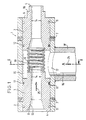
- the cooling tube 1 shown in Fig. 1 is part of a cooling section which comprises a plurality of such cooling tubes.
- the cooling tube 1 contains two clamping elements 3 of identical design in a tube section 2, between the facing end faces 4 and 5 of which a helical spring 6 is clamped.
- the two clamping elements 3 are fixed in the pipe section 2 by means of screws 7.
- the left end face 4 of the tensioning elements 3 each has an annular recess 8 and the right end face has ring shoulders 9 and 10.
- the coil spring 6 is seated with its left end on the inner annular shoulder 10 of the left clamping element 3 and with its right end in the annular recess 8 of the right clamping element 3.
- Each clamping element has two annular grooves 11.
- a sealing element 12 is provided in each of the annular grooves 11 adjacent to the helical spring 6.
- the two clamping elements 3 are designed as guide sleeves for the rolling stock and have a funnel 13 on the input side for this purpose.
- the inside diameter of the coil spring 6 is sufficiently larger than the inside diameter 14 of the clamping elements 3, so that it is ensured that the rolling stock does not come into contact with the coil spring.
- a sufficiently large annular space 15 must remain between the helical spring 6 and the inner wall of the tubular section 2 in order to ensure a radial inflow of coolant into the interior of the helical spring which is substantially uniform over the circumference of the helical spring.
- the annular space 15 is connected via a channel 16 to a connection for the cooling liquid.
- the channel is formed by a circular opening 17 in the pipe section 2 and a connecting pipe 18. 1 flows through the channel 16 from bottom to top (arrow 24) into the annular space 15 and from there through the helical gap 19 formed by the coil spring 6 into the interior of the coil spring 6.
- the rolling stock passes through the cooling tube 1 from left to right (arrow 25).
- the inner diameter 14 of the sleeve-shaped clamping elements 3 is approximately 1.5 to 3 times as large as the diameter of the rolling stock.
- the distance between the rolling stock and the inside of the coil spring 6 corresponds approximately to the distance between the outside of the coil spring and the inside wall of the pipe section 2.
- the production of the cooling tube shown in Fig. 1 is very simple. Sections of standardized commercially available pipes can be used as pipe sections. After drilling the opening 17, the connecting pipe 18 is welded on. Then one of the two clamping elements 3 already equipped with a seal 12 is inserted into the pipe section 2 and fixed with screws 7. Then the coil spring 6 is inserted and finally the other clamping element 3 and this is fixed with screws.
- the length of the helical spring 6 and the two clamping elements 3 is chosen so that the end face 4 of the left clamping element and the annular shoulder 9 of the right clamping element are flush with the pipe section 2.
- the flow cross section through the helical gap 19 is smaller than the flow cross section of the channel 16, so that it is ensured that the annular space 15 is always filled with coolant in the operating state.
- the sleeve-shaped tensioning elements 3 and the coil spring 6 are arranged coaxially within the tube section 2, so that the coil spring 6 is approximately the same distance from the inner wall of the tube cut 2 has.
- the helical spring 6 it can be expedient to offset the central axes of the tensioning elements 3 and the helical spring 6 somewhat parallel with respect to the central axis of the pipe section 2 in order to obtain an annular space 15 with a different cross section over the circumference.
- the coil spring only needs to be wound with changing pitch.
- the helical spring 6 it is also possible for the helical spring 6 to be conically tapered from one end to the other end.
- the channel 16 opens centrally into the annular space 15, ie. H. the central axis of the connecting pipe 18 intersects the central axis of the pipe section 2, which also represents the central axis of the clamping elements 3 and the coil spring 6.
- Fig. 3 shows a modified embodiment, in which the channel 16 opens eccentrically into the annular space 15.
- the central axis of the connecting pipe 18a is offset in parallel in comparison to the embodiment of Fig. 2, i. H. it no longer intersects the center line of the pipe section 2a.
- a tangential flow is generated within the annular space 15, which results in a rotation of the cooling liquid around the rolling stock through the gap 19 between the turns of the helical spring.
- This cooling therefore takes place with greater turbulence than in the example according to FIG. 2.
- FIG. 4 shows a cooling pipe in which two units, each consisting of a helical spring 6 clamped between two clamping elements 3, are arranged one behind the other in a pipe section 2b and the two units are connected by a rigid sleeve 20.
- Each of the coil springs is assigned an annular space 15 and a channel 16 for the supply of the coolant.
- the rigid sleeve 20 is clamped in the same way as the coil springs 6, namely between the inner shoulder 10 of one clamping element 3 and the annular recess 8 of the next clamping element 3.
- the rigid sleeve 20 creates a compensating distance, the length of which depends on the length of the rigid sleeve 20 can be determined.
- another element can be used which is permeable to the cooling liquid, and a channel opening into the annular space around this element can be provided, through which the cooling liquid supplied via the channel 16 is at least partially removed again.
- Fig. 5 shows an embodiment of the invention, which makes it possible not only in the manufacture, but also in the use of the cooling tube in a simple manner to adjust the flow cross section of the cooling liquid through the helical gap 19 of the coil spring 6 and to adapt it to the required conditions.
- the clamping length 21 between two clamping elements 3 can be changed. 5 corresponds essentially to that of FIG. 1.
- the right clamping element 3 is mounted in a longitudinally displaceable manner and lies with its end face facing away from the coil spring 6, in this case with the outer annular shoulder 9, on an adjusting ring 22 on, which is connected by a thread 23 to the pipe section 2c.
- the adjusting ring 22 is provided with an external thread and screwed into an internal thread on the right side of the pipe section 2c.
- the helical spring 6 can be compressed to a greater or lesser extent, thereby reducing the gap width 19 to a value of 0 within wide limits.
- the adjusting ring 22 is thus a simple means for adjusting and also for switching off the cooling liquid supplied to the rolling stock within the cooling tube.
- the threaded connection could also be provided between the right clamping element 3 and the pipe section 2c. In this case, the right clamping element would have to be rotated to change the clamping length 21.
- coolants are suitable as coolants; gaseous coolants could also be used.
Abstract
Description
Die Erfindung betrifft ein Kühlrohr gemäß dem Gattungsbegriff des Anspruches 1.The invention relates to a cooling tube according to the preamble of claim 1.
Derartige Kühlrohre kommen zum Kühlen des Walzguts in oder hinter einer Walzstraße zum Einsatz. Zum einen soll durch sie gewährleistet werden, daß innerhalb der Walzstraße die Temperaturen des Walzguts bestimmte Grenzwerte nicht übersteigen, damit es nicht zu einer unzulässigen Entkohlung oder Karbidausscheidung kommt. Zum anderen muß zur Einstellung eines bestimmten Gefüges des Walzguts die Endwalztemperatur am Fertigstich genau eingestellt werden. Schließlich sollen bestimmte mechanische Eigenschaften des Walzguts durch gezielte Kühlung nach dem letzten Walzgerüst eingestellt werden.Cooling tubes of this type are used to cool the rolling stock in or behind a rolling mill. On the one hand, it is intended to ensure that the temperatures of the rolling stock within the rolling mill do not exceed certain limit values, so that there is no impermissible decarburization or carbide precipitation. On the other hand, in order to set a certain structure of the rolling stock, the final rolling temperature on the finishing pass must be set exactly. Finally, certain mechanical properties of the rolling stock are to be adjusted by targeted cooling after the last rolling stand.
Durch die DE-C-2 726 473 ist ein Kühlrohr aus zwei im Abstand voneinander angeordneten Führungshülsen bekannt geworden, zwischen denen konvergierend von der einen Führungshülse zur anderen mehrere Stäbe auf einem Teilkreis um die Längsachse des Kühlrohrs mit Abstand voneinander angeordnet sind. Zwischen den einzelnen Stäben werden somit schlitzförmige Durchtrittsöffnungen für die Kühlflüssigkeit gebildet. Ein über die beiden Führungshülsen geschobener und mittels Dichtungselementen gegenüber diesem abgedichteter Rohrabschnitt bildet um die Stäbe einen Ringraum, der durch Kanäle mit einem Anschluß für die Kühlflüssigkeit in Verbindung steht. Die Einleitung der Kühlflüssigkeit kann hierbei tangential erfolgen, so daß eine Rotation der Kühlflüssigkeit um das Walzgut eintritt und durch die Turbulenz der Kühlflüssigkeit eine Verbesserung des Wärmeübergangs erzielt wird.From DE-C-2 726 473 a cooling tube is known from two spaced-apart guide sleeves, between which a plurality of rods are arranged convergingly from one guide sleeve to the other on a pitch circle around the longitudinal axis of the cooling tube at a distance from one another. Slot-like through openings for the cooling liquid are thus formed between the individual rods. A pipe section which is pushed over the two guide sleeves and sealed with respect to this by means of sealing elements forms an annular space around the rods, which is connected by channels to a connection for the coolant. The cooling liquid can be introduced tangentially, so that the cooling liquid rotates around the rolling stock and the turbulence of the cooling liquid improves the heat transfer.
Bekanntlich dürfen zur Beibehaltung der Rißfreiheit und der Gefügegleichmäßigkeit des Walzgutes bestimmte Temperaturunterschiede innerhalb des Walzgutes nicht überschritten werden. Je nach Walzgutdurchmesser, Temperatur oder Stahlgüte ist deshalb der Kühlmitteldurchsatz einzustellen. Da es bei bekannten Kühlrohren nicht ohne weiteres möglich ist, den Kühlmitteldurchsatz und damit die Intensität der Kühlung an die geforderte Kühlleistung anzupassen, wird üblicherweise ein aufwendiges Regelsystem mit Steuerorganen in den Zuleitungen zu den einzelnen Kühlrohren vorgesehen.As is known, in order to maintain freedom from cracks and the structural uniformity of the rolling stock, certain temperature differences within the rolling stock must not be exceeded. The coolant throughput must therefore be set depending on the diameter of the rolling stock, temperature or steel grade. Since it is not readily possible in known cooling tubes to adapt the coolant throughput and thus the intensity of the cooling to the required cooling capacity, a complex control system with control elements is usually provided in the feed lines to the individual cooling tubes.
Der Erfindung liegt die Aufgabe zugrunde, ein Kühlrohr zu schaffen, das bei einfachem konstruktivem Aufbau eine Einstellung des Kühlmitteldurchsatzes und damit eine Anpassung an die für das betreffende Kühlrohr vorgeschriebene Kühlleistung ermöglicht.The invention has for its object to provide a cooling tube that allows adjustment of the coolant throughput with a simple structural design and thus an adaptation to the cooling capacity prescribed for the cooling tube in question.
Die Aufgabe wird durch die Merkmale des Anspruches 1 gelöst. Vorteilhafte Ausgestaltungen der Erfindung sind den übrigen Ansprüchen zu entnehmen.The object is solved by the features of claim 1. Advantageous embodiments of the invention can be found in the remaining claims.
Die erfindungsgemäße Lösung zeichnet sich durch einen besonders einfachen konstruktiven Aufbau aus. Zwischen zwei hülsenförmigen Spannelementen, die vorzugsweise zugleich die Führung des Walzgutes bilden, ist eine Schraubenfeder eingespannt, deren Windungen normalerweise im Abstand voneinander gehalten werden, so daß sich ein wendelförmiger Spalt als Durchtrittsöffnung für die Kühlflüssigkeit ergibt. Obwohl bei geeigneter Einspannung zwischen den Spannelementen auch eine Zugfeder einsetzbar ist, wird vorzugsweise eine Druckfeder eingesetzt. Der Querschnitt des Drahtes, aus dem die Schraubenfeder gebildet ist, ist vorzugsweise rund. Der Innendurchmesser der Schraubenfeder ist ausreichend groß, um einerseits eine Berührung mit dem Walzgut zu verhindern und andererseits um das Walzgut herum einen ausreichenden Zwischenraum für den Zutritt der Kühlflüssigkeit zu schaffen.The solution according to the invention is characterized by a particularly simple construction. Between two sleeve-shaped clamping elements, which preferably also form the guide of the rolling stock, a helical spring is clamped, the turns of which are normally kept at a distance from one another, so that a helical gap results as a passage opening for the cooling liquid. Although a tension spring can also be used with suitable clamping between the tensioning elements, a compression spring is preferably used. The cross section of the wire from which the coil spring is formed is preferably round. The inside diameter of the helical spring is sufficiently large to prevent contact with the rolling stock on the one hand and to create a sufficient space for the access of the cooling liquid around the rolling stock.
Die beiden Spannelemente sind in einem Rohrabschnitt befestigt, der zugleich einen Ringraum um die Schraubenfeder begrenzt, in den ein Kanal für die Zufuhr der Kühlflüssigkeit mündet. Neben den für die Führung des Walzgutes ohnehin erforderlichen Spannelementen und neben Dichtungen und Befestigungsmitteln enthält somit das Kühlrohr lediglich noch eine Schraubenfeder und einen mit einem Wasseranschluß versehenen Rohrabschnitt. Die Spannelemente können hierbei identisch ausgebildet werden. Damit weist das Kühlrohr einen überraschend einfachen Aufbau auf. Trotzdem kann mit diesen Elementen einfach durch Ändern der Einspannlänge zwischen den Spannelementen die Schraubenfeder mehr oder weniger stark zusammengedrückt oder auseinandergezogen und durch die hierdurch bewirkte Änderung der Spaltbreite zwischen den Windungen der Kühlmitteldurchsatz an die gewünschte Kühlleistung angepaßt werden.The two clamping elements are fastened in a tube section which at the same time delimits an annular space around the helical spring, into which a channel for the supply of the coolant opens. In addition to the clamping elements required for guiding the rolling stock anyway, and in addition to seals and fastening means, the cooling tube thus only contains a coil spring and a pipe section provided with a water connection. The clamping elements can be designed identically. The cooling tube thus has a surprisingly simple structure. Nevertheless, with these elements, simply by changing the clamping length between the clamping elements, the coil spring can be compressed or pulled apart to a greater or lesser extent and the resulting change in the gap width between the turns of the coolant throughput can be adapted to the desired cooling capacity.
Dieses Prinzip erlaubt nicht nur eine einfache individuelle Einstellung des Kühlmitteldurchsatzes beim Zusammenbau des Kühlrohres, sondern eröffnet mit einfachen konstruktiven Mitteln auch die Möglichkeit, bei einem in die Kühlstrecke eingebauten Kühlrohr den Kühlmitteldurchsatz individuell verändern und der gewünschten Kühlleistung anpassen zu können. Zu diesem Zweck ist es lediglich erforderlich, die Konstruktion so auszubilden, daß die Einspannlänge zwischen den Spannelementen verändert werden kann. Insbesondere geeignet hierfür ist eine Gewindeverbindung, sei es unmittelbar zwischen wenigstens einem der Spannelemente und dem Rohrabschnitt, oder über einen Stellring.This principle not only allows simple adjustment of the coolant throughput when assembling the cooling tube, but also opens up the possibility with simple constructional means of being able to individually change the coolant throughput in a cooling tube built into the cooling section and to be able to adapt it to the desired cooling capacity. For this purpose, it is only necessary to design the construction so that the clamping length between the clamping elements can be changed. A threaded connection is particularly suitable for this, be it directly between at least one of the tensioning elements and the pipe section, or via an adjusting ring.
Die Spaltbreite zwischen den Windungen der Schraubenfeder muß nicht konstant ausgebildet sein. So kann an der Eintrittsseite des Walzgutes in die Feder die Spaltbreite größer als an der Austrittsseite ausgebildet sein. Dies ist beispielsweise dadurch möglich, daß die Schraubenfeder mit unterschiedlicher Steigung gewickelt ist. Es ist auch möglich, eine solche Charakteristik dadurch zu erreichen, daß die Schraubenfeder durch eine Reihenanordnung aus wenigstens zwei Schraubenfedern mit unterschiedlicher Steigung und gegebenenfalls unterschiedlicher Federkonstante ersetzt wird. Im übrigen ist es möglich, innerhalb eines Rohrabschnittes mehrere Schraubenfedern hintereinander anzuordnen, die jeweils zwischen Spannelementen eingespannt sind und denen jeweils ein Ringraum mit einem Kanal für die Kühlflüssigkeit zugeordnet ist. Einheiten aus jeweils einer zwischen zwei Spannelementen eingespannten Schraubenfeder, die hintereinander in einem Rohrabschnitt angeordnet sind, können jeweils durch eine starre Hülse verbunden sein, die für eine glatte Führung des mit dem Walzgut mitgenommenen Kühlmittelstroms sorgt. Durch derartige Anordnungen läßt sich die Abkühlcharakteristik innerhalb weiter Grenzen verändern. Bei dieser Gelegenheit soll noch erwähnt werden, daß der Kühlmitteldurchsatz durch den wendelförmigen Spalt zwischen den Windungen der Schraubenfeder in der Regel so eingestellt wird, daß er kleiner als der mögliche Durchsatz durch den in den Ringraum mündenden Kanal ist. Hierdurch soll gewährleistet sein, daß der Ringraum vollständig mit Kühlflüssigkeit gefüllt und das Walzgut auf seinem vollen Umfang gleichmäßig gekühlt wird. Durch exzentrische Einmündung des Kanals in den Ringraum ist es möglich, eine Rotation des Kühlwassers um das Walzgut zu erzielen und hierdurch die Kühlwirkung zu erhöhen. Die Einstellbarkeit des Kühlmitteldurchsatzes schließt auch den Fall ein, daß die Schraubenfeder bis zum gegenseitigen Anliegen benachbarter Windungen zusammengedrückt und damit der Kühlmitteldurchsatz vollständig unterbrochen wird.The gap width between the turns of the coil spring need not be constant. For example, the gap width on the entry side of the rolling stock into the spring can be larger than on the exit side. This is possible, for example, in that the coil spring is wound with a different pitch. It is also possible to achieve such a characteristic in that the coil spring consists of at least one row arrangement two coil springs with different pitch and possibly different spring constant is replaced. In addition, it is possible to arrange a plurality of coil springs one behind the other within a pipe section, each of which is clamped between clamping elements and to which an annular space with a channel for the coolant is assigned. Units each consisting of a helical spring clamped between two clamping elements, which are arranged one behind the other in a pipe section, can each be connected by a rigid sleeve, which ensures smooth guidance of the coolant flow entrained with the rolling stock. With such arrangements, the cooling characteristic can be changed within wide limits. On this occasion it should also be mentioned that the coolant throughput through the helical gap between the turns of the coil spring is generally set so that it is less than the possible throughput through the channel opening into the annular space. This is to ensure that the annular space is completely filled with cooling liquid and the rolling stock is cooled evenly over its entire circumference. By eccentrically opening the channel into the annular space, it is possible to achieve a rotation of the cooling water around the rolling stock and thereby to increase the cooling effect. The adjustability of the coolant throughput also includes the case that the helical spring is compressed until adjacent windings are in contact with one another and thus the coolant throughput is completely interrupted.
Im folgenden werden Ausführungsbeispiele der Erfindung anhand der Zeichnung näher erläutert. Es zeigen :
- Figur 1 eine Längsschnittansicht eines Kühlrohres,
Figur 2 den Schnitt 11-11 von Fig. 1,Figur 3 eine der Fig. 2 entsprechende Ansicht einer abgewandelten Ausführungsform eines Kühlrohres,- Figur 4 die Längsschnittansicht eines zwei Einheiten enthaltenden Kühlrohres, und
Figur 5 die Längsschnittansicht einer weiteren Ausführungsform eines Kühlrohres.
- FIG. 1 shows a longitudinal sectional view of a cooling tube,
- 2 shows the section 11-11 of Fig. 1,
- 3 shows a view corresponding to FIG. 2 of a modified embodiment of a cooling tube,
- Figure 4 is a longitudinal sectional view of a cooling tube containing two units, and
- Figure 5 shows the longitudinal sectional view of a further embodiment of a cooling tube.
Das in Fig. 1 dargestellte Kühlrohr 1 ist Bestandteil einer Kühlstrecke, die eine Vielzahl derartiger Kühlrohre umfaßt.The cooling tube 1 shown in Fig. 1 is part of a cooling section which comprises a plurality of such cooling tubes.
Das Kühlrohr 1 enthält zwei in einem Rohrabschnitt 2 identisch ausgebildete Spannelemente 3, zwischen deren einander zugewandten Stirnseiten 4 und 5 eine Schraubenfeder 6 eingespannt ist. Die beiden Spannelemente 3 sind mittels Schrauben 7 im Rohrabschnitt 2 fixiert. Die linke Stirnseite 4 der Spannelemente 3 weist jeweils eine ringförmige Ausnehmung 8 und die rechte Stirnseite Ringschultern 9 und 10 auf. Die Schraubenfeder 6 sitzt mit ihrem linken Ende auf der inneren Ringschulter 10 des linken Spannelementes 3 und mit ihrem rechten Ende in der ringförmigen Ausnehmung 8 des rechten Spannelementes 3.The cooling tube 1 contains two
Jedes Spannelement weist zwei Ringnuten 11 auf. In den zu der Schraubenfeder 6 benachbarten Ringnuten 11 ist jeweils ein Dichtelement 12 vorgesehen.Each clamping element has two
Die beiden Spannelemente 3 sind als Führungshülsen für das Walzgut ausgebildet und weisen zu diesem Zweck eingangsseitig einen Trichter 13 auf. Der Innendurchmesser der Schraubenfeder 6 ist ausreichend größer als der Innendurchmesser 14 der Spannelemente 3, damit gewährleistet ist, daß das Walzgut nicht mit der Schraubenfeder in Berührung kommt. Andererseits muß zwischen der Schraubenfeder 6 und der Innenwandung des Rohrabschnittes 2 ein ausreichend großer Ringraum 15 verbleiben, um einen im wesentlichen über den Umfang der Schraubenfeder gleichmäßigen radialen Zufluß des Kühlmittels in das Innere der Schraubenfeder zu gewährleisten. Der Ringraum 15 steht über einen Kanal 16 mit einem Anschluß für die Kühlflüssigkeit in Verbindung. Im vorliegenden Fall wird der Kanal durch eine kreisförmige Öffnung 17 im Rohrabschnitt 2 und ein Anschlußrohr 18 gebildet. Die Kühlflüssigkeit strömt bei der Darstellung nach Fig. 1 durch den Kanal 16 von unten nach oben (Pfeil 24) in den Ringraum 15 und von dort durch den durch die Schraubenfeder 6 gebildeten wendelförmigen Spalt 19 in das Innere der Schraubenfeder 6.The two
Im Betrieb durchläuft das Walzgut das Kühlrohr 1 von links nach rechts (Pfeil 25). Der Innendurchmesser 14 der hülsenförmigen Spannelemente 3 ist etwa 1, 5 bis 3 mal so groß wie der Walzgutdurchmesser. Der Abstand zwischen dem Walzgut und der Innenseite der Schraubenfeder 6 entspricht etwa dem Abstand zwischen der Außenseite der Schraubenfeder und der Innenwand des Rohrabschnittes 2.In operation, the rolling stock passes through the cooling tube 1 from left to right (arrow 25). The
Die Herstellung des in Fig. 1 dargestellten Kühlrohres ist sehr einfach. Als Rohrabschnitte können Abschnitte von genormten im Handel erhältlichen Rohren verwendet werden. Nach dem Bohren der Öffnung 17 wird das Anschlußrohr 18 aufgeschweißt. Danach wird eines der beiden bereits mit einer Dichtung 12 ausgestatteten Spannelemente 3 in den Rohrabschnitt 2 eingeschoben und mit Schrauben 7 fixiert. Dann wird die Schraubenfeder 6 eingesetzt und schließlich das andere Spannelement 3 und dieses mit Schrauben fixiert.The production of the cooling tube shown in Fig. 1 is very simple. Sections of standardized commercially available pipes can be used as pipe sections. After drilling the
Bei dem dargestellten Ausführungsbeispiel ist die Länge der Schraubenfeder 6 und der beiden Spannelemente 3 so gewählt, daß die Stirnfläche 4 des linken Spannelementes und die Ringschulter 9 des rechten Spannelementes bündig mit dem Rohrabschnitt 2 abschließen. Der Durchflußquerschnitt durch den wendelförmigen Spalt 19 ist kleiner als der Durchflußquerschnitt des Kanals 16, so daß gewährleistet ist, daß der Ringraum 15 im Betriebszustand stets mit Kühlflüssigkeit gefüllt ist. Die hülsenförmigen Spannelemente 3 und die Schraubenfeder 6 sind koaxial innerhalb des Rohrabschnittes 2 angeordnet, so daß die Schraubenfeder 6 etwa überall den gleichen Abstand von der Innenwand des Rohrabschnittes 2 hat. Es kann jedoch aus strömungstechnischen Gründen zweckmäßig sein, die Mittelachsen der Spannelemente 3 und der Schraubenfeder 6 gegenüber der Mittelachse des Rohrabschnittes 2 etwas parallel zu versetzen, um einen Ringraum 15 mit über den Umfang unterschiedlichem Querschnitt zu erhalten. Außerdem kann es zweckmäßig sein, die Breite des wendelförmigen Spaltes 19 nicht konstant, wie dargestellt, sondern z. B. von links nach rechts abnehmend auszubilden. Zu diesem Zweck braucht die Schraubenfeder nur mit sich verändernder Steigung gewickelt zu werden. Schließlich ist es auch möglich, die Schraubenfeder 6 von dem einen Ende zu dem anderen Ende sich konisch verjüngend auszubilden.In the illustrated embodiment, the length of the
Wie aus der Querschnittsansicht nach Fig. 2 hervorgeht, mündet bei dem dargestellten Ausführungsbeispiel der Kanal 16 zentrisch in den Ringraum 15, d. h. die Mittelachse des Anschlußrohres 18 schneidet die Mittelachse des Rohrabschnittes 2, die zugleich die Mittelachse der Spannelemente 3 und der Schraubenfeder 6 darstellt.As can be seen from the cross-sectional view according to FIG. 2, in the exemplary embodiment shown, the
Fig. 3 zeigt eine demgegenüber abgewandelte Ausführungsform, bei der der Kanal 16 exzentrisch in den Ringraum 15 mündet. Zu diesem Zweck ist die Mittelachse des Anschlußrohres 18a im Vergleich zur Ausführungsform von Fig. 2 parallel versetzt, d. h. sie schneidet nicht mehr die Mittellinie des Rohrabschnittes 2a. Auf diese Weise wird innerhalb des Ringraumes 15 eine tangentiale Strömung erzeugt, die durch den Spalt 19 zwischen den Windungen der Schraubenfeder hindurch eine Rotation der Kühlflüssigkeit um das Walzgut zur Folge hat. Diese Kühlung erfolgt somit mit stärkerer Turbulenz als bei dem Beispiel nach Fig. 2.Fig. 3 shows a modified embodiment, in which the
Fig. 4 stellt ein Kühlrohr dar, bei dem in einem Rohrabschnitt 2b zwei Einheiten aus jeweils einer zwischen zwei Spannelementen 3 eingespannten Schraubenfeder 6 hintereinander angeordnet und die beiden Einheiten durch eine starre Hülse 20 verbunden sind. Jeder der Schraubenfedern ist ein Ringraum 15 und ein Kanal 16 für die Zuleitung der Kühlflüssigkeit zugeordnet. Die starre Hülse 20 ist in gleicher Weise wie die Schraubenfedern 6 eingespannt, nämlich zwischen der inneren Schulter 10 des einen Spannelementes 3 und der ringförmigen Ausnehmung 8 des nächsten Spannelementes 3. Durch die starre Hülse 20 wird eine Ausgleichsstrecke geschaffen, deren Länge durch die Länge der starren Hülse 20 bestimmt werden kann.FIG. 4 shows a cooling pipe in which two units, each consisting of a
Anstelle der starren Hülse 20 kann auch ein anderes Element eingesetzt werden, das fur die Kühlflüssigkeit durchlässig ist, und es kann ein in den Ringraum um dieses Element mündender Kanal vorgesehen werden, durch den die über den Kanal 16 zugeführte Kühlflüssigkeit wenigstens teilweise wieder abgeführt wird.Instead of the
Fig. 5 zeigt eine Ausführungsform der Erfindung, die es nicht nur bei der Herstellung, sondern auch im Einsatz des Kühlrohres auf einfache Weise ermöglicht, den Durchflußquerschnitt der Kühlflüssigkeit durch den wendelförmigen Spalt 19 der Schraubenfeder 6 einzustellen und den geforderten Bedingungen anzupassen. Zu diesem Zweck ist die Einspannlänge 21 zwischen zwei Spannelementen 3 veränderbar. Die Ausführungsform gemäß Fig. 5 entspricht im wesentlichen der nach Fig. 1. Zur Veränderung der Einspannlänge 21 ist das rechte Spannelement 3 längsverschiebbar gelagert und liegt mit seiner der Schraubenfeder 6 abgewandten Stirnseite, in diesem Fall mit der äußeren Ringschulter 9, an einem Stellring 22 an, der durch ein Gewinde 23 mit dem Rohrabschnitt 2c verbunden ist. Der Stellring 22 ist zu diesem Zweck mit einem Außengewinde versehen und in ein Innengewinde auf der rechten Seite des Rohrabschnittes 2c eingeschraubt. Durch Drehen des Verstellrings 22 läßt sich die Schraubenfeder 6 mehr oder weniger stark zusammendrücken und hierdurch die Spaltbreite 19 in weiten Grenzen bis zum Wert 0 verringern. Der Stellring 22 ist somit ein einfaches Mittel zum Einstellen und auch zum Abschalten der dem Walzgut innerhalb des Kühlrohres zugeführten Kühlflüssigkeit.Fig. 5 shows an embodiment of the invention, which makes it possible not only in the manufacture, but also in the use of the cooling tube in a simple manner to adjust the flow cross section of the cooling liquid through the
Die Gewindeverbindung könnte auch zwischen dem rechten Spannelement 3 und dem Rohrabschnitt 2c vorgesehen werden. In diesem Fall müßte zum Verändern der Einspannlänge 21 das rechte Spannelement gedreht werden.The threaded connection could also be provided between the
Als Kühlmittel eignet sich nicht nur eine Kühlflüssigkeit und hier insbesondere Wasser ; es könnten auch gasförmige Kühlmittel zum Einsatz gelangen.Not only a coolant and especially water are suitable as coolants; gaseous coolants could also be used.
Claims (11)
Priority Applications (1)
| Application Number | Priority Date | Filing Date | Title |
|---|---|---|---|
| AT84113898T ATE28135T1 (en) | 1983-11-23 | 1984-11-16 | COOLING PIPE FOR A COOLING LINE FOR RAPID COOLING OF WIRE ROD OR BAR MATERIAL. |
Applications Claiming Priority (2)
| Application Number | Priority Date | Filing Date | Title |
|---|---|---|---|
| DE3342322A DE3342322C2 (en) | 1983-11-23 | 1983-11-23 | Cooling tube for a cooling section for the rapid cooling of rolling stock |
| DE3342322 | 1983-11-23 |
Publications (2)
| Publication Number | Publication Date |
|---|---|
| EP0144029A1 EP0144029A1 (en) | 1985-06-12 |
| EP0144029B1 true EP0144029B1 (en) | 1987-07-08 |
Family
ID=6215042
Family Applications (1)
| Application Number | Title | Priority Date | Filing Date |
|---|---|---|---|
| EP84113898A Expired EP0144029B1 (en) | 1983-11-23 | 1984-11-16 | Cooling tube for a cooling section for rapidly cooling steel wire rod or rod stock |
Country Status (5)
| Country | Link |
|---|---|
| US (1) | US4629165A (en) |
| EP (1) | EP0144029B1 (en) |
| JP (1) | JPS60133912A (en) |
| AT (1) | ATE28135T1 (en) |
| DE (1) | DE3342322C2 (en) |
Families Citing this family (7)
| Publication number | Priority date | Publication date | Assignee | Title |
|---|---|---|---|---|
| DE4201295A1 (en) * | 1992-01-15 | 1993-07-22 | Thaelmann Schwermaschbau Veb | Device for guiding and cooling rolled material in wire rolling blocks - uses pressure water feed arranged on guide by flanges, water quantity is adjusted by diaphragm in feed nozzle |
| US5329779A (en) * | 1993-02-09 | 1994-07-19 | C.V.G. Siderurgica Del Orinoco, C.A. | Method and apparatus for cooling workpieces |
| US5447293A (en) * | 1994-07-22 | 1995-09-05 | Clarke; Beresford N. | Method and apparatus for quenching heat treated objects |
| US5518222A (en) * | 1994-10-28 | 1996-05-21 | Tuscaloosa Steel Corporation | Nozzle arrangement for use in a cooling zone of rolling mill |
| DE19503544A1 (en) * | 1995-02-03 | 1996-08-08 | Achenbach Buschhuetten Gmbh | Roll cooling and/or lubricating appts. for cold-rolling |
| DE102020205249B3 (en) * | 2020-04-24 | 2021-10-07 | Kocks Technik Gmbh & Co Kg | Device for cooling long products |
| CN112553441A (en) * | 2020-12-09 | 2021-03-26 | 山东南山铝业股份有限公司 | Aviation aluminum alloy high accuracy aging treatment furnace |
Family Cites Families (6)
| Publication number | Priority date | Publication date | Assignee | Title |
|---|---|---|---|---|
| DE2726473C2 (en) * | 1977-06-11 | 1979-08-30 | Stahlwerke Peine-Salzgitter Ag, 3150 Peine | KUhlmitteUelt- and rolling stock guide device for the intermittent cooling of rolling stock, especially wire, fine iron and the like |
| DE2822582C3 (en) * | 1978-05-24 | 1981-07-30 | Stahlwerke Peine-Salzgitter Ag, 3150 Peine | Coolant guide and rolling stock guide device for the intermittent cooling of rolling stock, in particular wire, fine iron or the like. |
| DE8019956U1 (en) * | 1980-07-25 | 1981-11-12 | Korf-Stahl Ag, 7570 Baden-Baden | Cooling tube for a cooling section for rapid cooling of wire rod or rod material |
| US4329861A (en) * | 1980-08-21 | 1982-05-18 | Orion Machinery And Engineering Corporation | Method and apparatus for drawing and cooling wire |
| US4332155A (en) * | 1980-12-18 | 1982-06-01 | Morgan Construction Company | Rolling mill laying pipe |
| SU995952A1 (en) * | 1981-07-13 | 1983-02-15 | Предприятие П/Я М-5481 | Apparatus for cooling rounds |
-
1983
- 1983-11-23 DE DE3342322A patent/DE3342322C2/en not_active Expired
-
1984
- 1984-11-09 US US06/670,058 patent/US4629165A/en not_active Expired - Fee Related
- 1984-11-16 AT AT84113898T patent/ATE28135T1/en not_active IP Right Cessation
- 1984-11-16 EP EP84113898A patent/EP0144029B1/en not_active Expired
- 1984-11-22 JP JP59246386A patent/JPS60133912A/en active Granted
Also Published As
| Publication number | Publication date |
|---|---|
| JPH025484B2 (en) | 1990-02-02 |
| ATE28135T1 (en) | 1987-07-15 |
| DE3342322A1 (en) | 1985-06-05 |
| DE3342322C2 (en) | 1986-09-18 |
| JPS60133912A (en) | 1985-07-17 |
| EP0144029A1 (en) | 1985-06-12 |
| US4629165A (en) | 1986-12-16 |
Similar Documents
| Publication | Publication Date | Title |
|---|---|---|
| DE3014891C2 (en) | ||
| EP2328738B1 (en) | Temperature-controlled stretch rod | |
| DE2505657C3 (en) | Steam recirculation valve | |
| DE3029798C2 (en) | ||
| DE2238182A1 (en) | FLOW CONTROL SYSTEM AND PROCEDURE FOR ITS CALIBRATION | |
| EP0144029B1 (en) | Cooling tube for a cooling section for rapidly cooling steel wire rod or rod stock | |
| DE3824073C2 (en) | oil cooler | |
| DE2649237A1 (en) | CORE ROD WITH TEMPERATURE CONTROL FOR AN INJECTION BLOW MOLDING MACHINE | |
| EP0761854B1 (en) | False-twisting machine with pneumatic yarn insert guide | |
| DE3814248A1 (en) | ADJUSTABLE CHECK VALVE | |
| DE4221897C2 (en) | Device for the filtration of liquid or gaseous media | |
| DE1959446C3 (en) | Valve for converting superheated high pressure steam into steam of lower pressure and temperature | |
| DD201762A5 (en) | SCREW PRESS | |
| EP1208924A2 (en) | Wire cooling device | |
| DE2822582B2 (en) | Coolant guide and rolling stock guide device for the intermittent cooling of rolling stock, in particular wire, fine iron or the like | |
| DE3100639C2 (en) | Shut-off and regulating device of a steam converting valve | |
| DE4319006A1 (en) | Heater/radiator (cooler) seal | |
| DE3419769C2 (en) | ||
| WO2003066315A1 (en) | Blowing head for extruding films, comprising clamping elements containing ducts for cooling air | |
| DE3740123A1 (en) | Heatable screw nozzle | |
| CH354931A (en) | Extruder | |
| DE3011670C2 (en) | ||
| DE4238960A1 (en) | Device for cooling profiles | |
| DE1937735C (en) | Device for mixing two media whose temperatures differ greatly from one another | |
| EP3812123A1 (en) | Extrusion system and calibration device for use in an extrusion system for plastic pipes |
Legal Events
| Date | Code | Title | Description |
|---|---|---|---|
| PUAI | Public reference made under article 153(3) epc to a published international application that has entered the european phase |
Free format text: ORIGINAL CODE: 0009012 |
|
| 17P | Request for examination filed |
Effective date: 19841116 |
|
| AK | Designated contracting states |
Designated state(s): AT BE CH DE FR GB IT LI LU NL SE |
|
| 17Q | First examination report despatched |
Effective date: 19861121 |
|
| GRAA | (expected) grant |
Free format text: ORIGINAL CODE: 0009210 |
|
| AK | Designated contracting states |
Kind code of ref document: B1 Designated state(s): AT BE FR GB IT LU |
|
| REF | Corresponds to: |
Ref document number: 28135 Country of ref document: AT Date of ref document: 19870715 Kind code of ref document: T |
|
| ET | Fr: translation filed | ||
| ITF | It: translation for a ep patent filed |
Owner name: DE DOMINICIS & MAYER S.R.L. |
|
| RAP2 | Party data changed (patent owner data changed or rights of a patent transferred) |
Owner name: ROTHE, HERBERT |
|
| BECH | Be: change of holder |
Free format text: 870708 *ROTHE HERBERT |
|
| REG | Reference to a national code |
Ref country code: GB Ref legal event code: 732 |
|
| PLBE | No opposition filed within time limit |
Free format text: ORIGINAL CODE: 0009261 |
|
| STAA | Information on the status of an ep patent application or granted ep patent |
Free format text: STATUS: NO OPPOSITION FILED WITHIN TIME LIMIT |
|
| 26N | No opposition filed | ||
| PG25 | Lapsed in a contracting state [announced via postgrant information from national office to epo] |
Ref country code: BE Effective date: 19881130 |
|
| BERE | Be: lapsed |
Owner name: ROTHE HERBERT Effective date: 19881130 |
|
| ITTA | It: last paid annual fee | ||
| EPTA | Lu: last paid annual fee | ||
| PGFP | Annual fee paid to national office [announced via postgrant information from national office to epo] |
Ref country code: GB Payment date: 19950922 Year of fee payment: 12 Ref country code: FR Payment date: 19950922 Year of fee payment: 12 |
|
| PGFP | Annual fee paid to national office [announced via postgrant information from national office to epo] |
Ref country code: LU Payment date: 19951001 Year of fee payment: 12 |
|
| PGFP | Annual fee paid to national office [announced via postgrant information from national office to epo] |
Ref country code: AT Payment date: 19951025 Year of fee payment: 12 |
|
| PG25 | Lapsed in a contracting state [announced via postgrant information from national office to epo] |
Ref country code: LU Free format text: LAPSE BECAUSE OF NON-PAYMENT OF DUE FEES Effective date: 19961116 Ref country code: GB Effective date: 19961116 Ref country code: AT Effective date: 19961116 |
|
| GBPC | Gb: european patent ceased through non-payment of renewal fee |
Effective date: 19961116 |
|
| PG25 | Lapsed in a contracting state [announced via postgrant information from national office to epo] |
Ref country code: FR Effective date: 19970731 |
|
| REG | Reference to a national code |
Ref country code: FR Ref legal event code: ST |