EP1527804A1 - Verfahren und Vorrichtung zur Gas-Flüssigkeitstrennung - Google Patents
Verfahren und Vorrichtung zur Gas-Flüssigkeitstrennung Download PDFInfo
- Publication number
- EP1527804A1 EP1527804A1 EP04025768A EP04025768A EP1527804A1 EP 1527804 A1 EP1527804 A1 EP 1527804A1 EP 04025768 A EP04025768 A EP 04025768A EP 04025768 A EP04025768 A EP 04025768A EP 1527804 A1 EP1527804 A1 EP 1527804A1
- Authority
- EP
- European Patent Office
- Prior art keywords
- gas
- liquid separation
- reaction
- liquid
- pipe
- Prior art date
- Legal status (The legal status is an assumption and is not a legal conclusion. Google has not performed a legal analysis and makes no representation as to the accuracy of the status listed.)
- Ceased
Links
- 239000007788 liquid Substances 0.000 title claims abstract description 183
- 238000000926 separation method Methods 0.000 title claims abstract description 135
- 238000006243 chemical reaction Methods 0.000 claims abstract description 96
- 239000012295 chemical reaction liquid Substances 0.000 claims abstract description 86
- 239000006227 byproduct Substances 0.000 claims abstract description 65
- 238000002156 mixing Methods 0.000 claims description 212
- 239000007789 gas Substances 0.000 claims description 88
- 229910052751 metal Inorganic materials 0.000 claims description 61
- 239000002184 metal Substances 0.000 claims description 61
- 239000011859 microparticle Substances 0.000 claims description 59
- 238000010926 purge Methods 0.000 claims description 11
- 239000011261 inert gas Substances 0.000 claims description 10
- 239000003638 chemical reducing agent Substances 0.000 claims description 7
- 230000003247 decreasing effect Effects 0.000 claims description 5
- 229910021645 metal ion Inorganic materials 0.000 claims description 5
- 230000000737 periodic effect Effects 0.000 claims description 4
- 239000000243 solution Substances 0.000 description 129
- 238000000034 method Methods 0.000 description 55
- 239000002082 metal nanoparticle Substances 0.000 description 28
- 239000000203 mixture Substances 0.000 description 28
- 239000002245 particle Substances 0.000 description 26
- 238000007872 degassing Methods 0.000 description 20
- 238000007796 conventional method Methods 0.000 description 19
- 239000004094 surface-active agent Substances 0.000 description 17
- XLYOFNOQVPJJNP-UHFFFAOYSA-N water Substances O XLYOFNOQVPJJNP-UHFFFAOYSA-N 0.000 description 17
- 238000003756 stirring Methods 0.000 description 16
- 239000000693 micelle Substances 0.000 description 14
- OKKJLVBELUTLKV-UHFFFAOYSA-N Methanol Chemical compound OC OKKJLVBELUTLKV-UHFFFAOYSA-N 0.000 description 12
- QVGXLLKOCUKJST-UHFFFAOYSA-N atomic oxygen Chemical compound [O] QVGXLLKOCUKJST-UHFFFAOYSA-N 0.000 description 12
- 239000001301 oxygen Substances 0.000 description 12
- 229910052760 oxygen Inorganic materials 0.000 description 12
- 239000000126 substance Substances 0.000 description 12
- 238000002360 preparation method Methods 0.000 description 11
- 238000009775 high-speed stirring Methods 0.000 description 10
- RTZKZFJDLAIYFH-UHFFFAOYSA-N Diethyl ether Chemical compound CCOCC RTZKZFJDLAIYFH-UHFFFAOYSA-N 0.000 description 9
- 229910005335 FePt Inorganic materials 0.000 description 9
- 238000010438 heat treatment Methods 0.000 description 9
- 239000000463 material Substances 0.000 description 9
- 238000009826 distribution Methods 0.000 description 7
- 238000010924 continuous production Methods 0.000 description 6
- DIOQZVSQGTUSAI-UHFFFAOYSA-N decane Chemical compound CCCCCCCCCC DIOQZVSQGTUSAI-UHFFFAOYSA-N 0.000 description 6
- 239000010408 film Substances 0.000 description 6
- 238000011084 recovery Methods 0.000 description 6
- UFHFLCQGNIYNRP-UHFFFAOYSA-N Hydrogen Chemical compound [H][H] UFHFLCQGNIYNRP-UHFFFAOYSA-N 0.000 description 5
- 150000001335 aliphatic alkanes Chemical class 0.000 description 5
- 238000004458 analytical method Methods 0.000 description 5
- 239000012071 phase Substances 0.000 description 5
- 239000002994 raw material Substances 0.000 description 5
- 239000002904 solvent Substances 0.000 description 5
- IJGRMHOSHXDMSA-UHFFFAOYSA-N Atomic nitrogen Chemical compound N#N IJGRMHOSHXDMSA-UHFFFAOYSA-N 0.000 description 4
- IMNFDUFMRHMDMM-UHFFFAOYSA-N N-Heptane Chemical group CCCCCCC IMNFDUFMRHMDMM-UHFFFAOYSA-N 0.000 description 4
- 239000007864 aqueous solution Substances 0.000 description 4
- 230000006837 decompression Effects 0.000 description 4
- 230000000368 destabilizing effect Effects 0.000 description 4
- 238000007599 discharging Methods 0.000 description 4
- 239000006185 dispersion Substances 0.000 description 4
- 239000007791 liquid phase Substances 0.000 description 4
- 238000004519 manufacturing process Methods 0.000 description 4
- 238000005259 measurement Methods 0.000 description 4
- 239000003960 organic solvent Substances 0.000 description 4
- 230000002093 peripheral effect Effects 0.000 description 4
- 238000012545 processing Methods 0.000 description 4
- 238000010008 shearing Methods 0.000 description 4
- 239000007795 chemical reaction product Substances 0.000 description 3
- 229910003460 diamond Inorganic materials 0.000 description 3
- 239000010432 diamond Substances 0.000 description 3
- 230000000694 effects Effects 0.000 description 3
- 239000011259 mixed solution Substances 0.000 description 3
- LFQSCWFLJHTTHZ-UHFFFAOYSA-N Ethanol Chemical compound CCO LFQSCWFLJHTTHZ-UHFFFAOYSA-N 0.000 description 2
- 239000003463 adsorbent Substances 0.000 description 2
- 239000000443 aerosol Substances 0.000 description 2
- 238000004364 calculation method Methods 0.000 description 2
- 239000000919 ceramic Substances 0.000 description 2
- 150000001875 compounds Chemical class 0.000 description 2
- 230000001627 detrimental effect Effects 0.000 description 2
- SNRUBQQJIBEYMU-UHFFFAOYSA-N dodecane Chemical compound CCCCCCCCCCCC SNRUBQQJIBEYMU-UHFFFAOYSA-N 0.000 description 2
- -1 hydrogen gas Chemical compound 0.000 description 2
- 238000009616 inductively coupled plasma Methods 0.000 description 2
- XEEYBQQBJWHFJM-UHFFFAOYSA-N iron Substances [Fe] XEEYBQQBJWHFJM-UHFFFAOYSA-N 0.000 description 2
- 238000003754 machining Methods 0.000 description 2
- BKIMMITUMNQMOS-UHFFFAOYSA-N nonane Chemical compound CCCCCCCCC BKIMMITUMNQMOS-UHFFFAOYSA-N 0.000 description 2
- NJPPVKZQTLUDBO-UHFFFAOYSA-N novaluron Chemical compound C1=C(Cl)C(OC(F)(F)C(OC(F)(F)F)F)=CC=C1NC(=O)NC(=O)C1=C(F)C=CC=C1F NJPPVKZQTLUDBO-UHFFFAOYSA-N 0.000 description 2
- TVMXDCGIABBOFY-UHFFFAOYSA-N octane Chemical compound CCCCCCCC TVMXDCGIABBOFY-UHFFFAOYSA-N 0.000 description 2
- 230000009257 reactivity Effects 0.000 description 2
- 150000003839 salts Chemical class 0.000 description 2
- 238000001179 sorption measurement Methods 0.000 description 2
- 230000003068 static effect Effects 0.000 description 2
- RSJKGSCJYJTIGS-UHFFFAOYSA-N undecane Chemical compound CCCCCCCCCCC RSJKGSCJYJTIGS-UHFFFAOYSA-N 0.000 description 2
- WRIDQFICGBMAFQ-UHFFFAOYSA-N (E)-8-Octadecenoic acid Natural products CCCCCCCCCC=CCCCCCCC(O)=O WRIDQFICGBMAFQ-UHFFFAOYSA-N 0.000 description 1
- QGLWBTPVKHMVHM-KTKRTIGZSA-N (z)-octadec-9-en-1-amine Chemical compound CCCCCCCC\C=C/CCCCCCCCN QGLWBTPVKHMVHM-KTKRTIGZSA-N 0.000 description 1
- DURPTKYDGMDSBL-UHFFFAOYSA-N 1-butoxybutane Chemical compound CCCCOCCCC DURPTKYDGMDSBL-UHFFFAOYSA-N 0.000 description 1
- JLBXCKSMESLGTJ-UHFFFAOYSA-N 1-ethoxypropan-1-ol Chemical compound CCOC(O)CC JLBXCKSMESLGTJ-UHFFFAOYSA-N 0.000 description 1
- ZNQVEEAIQZEUHB-UHFFFAOYSA-N 2-ethoxyethanol Chemical compound CCOCCO ZNQVEEAIQZEUHB-UHFFFAOYSA-N 0.000 description 1
- LQJBNNIYVWPHFW-UHFFFAOYSA-N 20:1omega9c fatty acid Natural products CCCCCCCCCCC=CCCCCCCCC(O)=O LQJBNNIYVWPHFW-UHFFFAOYSA-N 0.000 description 1
- QSBYPNXLFMSGKH-UHFFFAOYSA-N 9-Heptadecensaeure Natural products CCCCCCCC=CCCCCCCCC(O)=O QSBYPNXLFMSGKH-UHFFFAOYSA-N 0.000 description 1
- LZZYPRNAOMGNLH-UHFFFAOYSA-M Cetrimonium bromide Chemical compound [Br-].CCCCCCCCCCCCCCCC[N+](C)(C)C LZZYPRNAOMGNLH-UHFFFAOYSA-M 0.000 description 1
- WSFSSNUMVMOOMR-UHFFFAOYSA-N Formaldehyde Chemical compound O=C WSFSSNUMVMOOMR-UHFFFAOYSA-N 0.000 description 1
- NHTMVDHEPJAVLT-UHFFFAOYSA-N Isooctane Chemical compound CC(C)CC(C)(C)C NHTMVDHEPJAVLT-UHFFFAOYSA-N 0.000 description 1
- 229910020427 K2PtCl4 Inorganic materials 0.000 description 1
- ZQPPMHVWECSIRJ-UHFFFAOYSA-N Oleic acid Natural products CCCCCCCCC=CCCCCCCCC(O)=O ZQPPMHVWECSIRJ-UHFFFAOYSA-N 0.000 description 1
- 239000005642 Oleic acid Substances 0.000 description 1
- ZLMJMSJWJFRBEC-UHFFFAOYSA-N Potassium Chemical compound [K] ZLMJMSJWJFRBEC-UHFFFAOYSA-N 0.000 description 1
- 230000001133 acceleration Effects 0.000 description 1
- 230000002411 adverse Effects 0.000 description 1
- 150000001298 alcohols Chemical class 0.000 description 1
- 239000012298 atmosphere Substances 0.000 description 1
- 125000004429 atom Chemical group 0.000 description 1
- 238000000889 atomisation Methods 0.000 description 1
- 238000005422 blasting Methods 0.000 description 1
- 125000004432 carbon atom Chemical group C* 0.000 description 1
- 230000006835 compression Effects 0.000 description 1
- 238000007906 compression Methods 0.000 description 1
- 239000013078 crystal Substances 0.000 description 1
- 238000005520 cutting process Methods 0.000 description 1
- 238000013461 design Methods 0.000 description 1
- JVSWJIKNEAIKJW-UHFFFAOYSA-N dimethyl-hexane Natural products CCCCCC(C)C JVSWJIKNEAIKJW-UHFFFAOYSA-N 0.000 description 1
- 229910001873 dinitrogen Inorganic materials 0.000 description 1
- POLCUAVZOMRGSN-UHFFFAOYSA-N dipropyl ether Chemical compound CCCOCCC POLCUAVZOMRGSN-UHFFFAOYSA-N 0.000 description 1
- 238000001035 drying Methods 0.000 description 1
- 238000007429 general method Methods 0.000 description 1
- 239000011521 glass Substances 0.000 description 1
- 238000000227 grinding Methods 0.000 description 1
- 230000020169 heat generation Effects 0.000 description 1
- 229910052742 iron Inorganic materials 0.000 description 1
- QXJSBBXBKPUZAA-UHFFFAOYSA-N isooleic acid Natural products CCCCCCCC=CCCCCCCCCC(O)=O QXJSBBXBKPUZAA-UHFFFAOYSA-N 0.000 description 1
- LAPRIVJANDLWOK-UHFFFAOYSA-N laureth-5 Chemical compound CCCCCCCCCCCCOCCOCCOCCOCCOCCO LAPRIVJANDLWOK-UHFFFAOYSA-N 0.000 description 1
- 239000006249 magnetic particle Substances 0.000 description 1
- 230000005415 magnetization Effects 0.000 description 1
- 230000014759 maintenance of location Effects 0.000 description 1
- 238000010297 mechanical methods and process Methods 0.000 description 1
- 229910001092 metal group alloy Inorganic materials 0.000 description 1
- 150000002739 metals Chemical class 0.000 description 1
- 239000002105 nanoparticle Substances 0.000 description 1
- 229910052759 nickel Inorganic materials 0.000 description 1
- 238000005121 nitriding Methods 0.000 description 1
- 229910052757 nitrogen Inorganic materials 0.000 description 1
- ZQPPMHVWECSIRJ-KTKRTIGZSA-N oleic acid Chemical compound CCCCCCCC\C=C/CCCCCCCC(O)=O ZQPPMHVWECSIRJ-KTKRTIGZSA-N 0.000 description 1
- 229910052763 palladium Inorganic materials 0.000 description 1
- 238000005192 partition Methods 0.000 description 1
- 229910052697 platinum Inorganic materials 0.000 description 1
- 229910052700 potassium Inorganic materials 0.000 description 1
- 239000011591 potassium Substances 0.000 description 1
- 239000000047 product Substances 0.000 description 1
- 125000001453 quaternary ammonium group Chemical class 0.000 description 1
- 238000010791 quenching Methods 0.000 description 1
- 230000000171 quenching effect Effects 0.000 description 1
- 230000002829 reductive effect Effects 0.000 description 1
- 230000002441 reversible effect Effects 0.000 description 1
- 239000013049 sediment Substances 0.000 description 1
- 238000005245 sintering Methods 0.000 description 1
- 239000012279 sodium borohydride Substances 0.000 description 1
- 229910000033 sodium borohydride Inorganic materials 0.000 description 1
- APSBXTVYXVQYAB-UHFFFAOYSA-M sodium docusate Chemical compound [Na+].CCCCC(CC)COC(=O)CC(S([O-])(=O)=O)C(=O)OCC(CC)CCCC APSBXTVYXVQYAB-UHFFFAOYSA-M 0.000 description 1
- 239000007787 solid Substances 0.000 description 1
- 230000006641 stabilisation Effects 0.000 description 1
- 238000011105 stabilization Methods 0.000 description 1
- 230000000087 stabilizing effect Effects 0.000 description 1
- 150000005846 sugar alcohols Polymers 0.000 description 1
- BDHFUVZGWQCTTF-UHFFFAOYSA-M sulfonate Chemical compound [O-]S(=O)=O BDHFUVZGWQCTTF-UHFFFAOYSA-M 0.000 description 1
- 239000006228 supernatant Substances 0.000 description 1
- 230000003746 surface roughness Effects 0.000 description 1
- 238000012360 testing method Methods 0.000 description 1
- 239000010409 thin film Substances 0.000 description 1
- 238000001926 trapping method Methods 0.000 description 1
- LVWHKVQBJNDDEL-UHFFFAOYSA-K triazanium iron(3+) oxalate trihydrate Chemical compound [NH4+].[NH4+].[NH4+].O.O.O.[Fe+3].[O-]C(=O)C([O-])=O.[O-]C(=O)C([O-])=O.[O-]C(=O)C([O-])=O LVWHKVQBJNDDEL-UHFFFAOYSA-K 0.000 description 1
Images






Classifications
-
- B—PERFORMING OPERATIONS; TRANSPORTING
- B01—PHYSICAL OR CHEMICAL PROCESSES OR APPARATUS IN GENERAL
- B01D—SEPARATION
- B01D19/00—Degasification of liquids
- B01D19/0036—Flash degasification
-
- B—PERFORMING OPERATIONS; TRANSPORTING
- B01—PHYSICAL OR CHEMICAL PROCESSES OR APPARATUS IN GENERAL
- B01D—SEPARATION
- B01D19/00—Degasification of liquids
- B01D19/0042—Degasification of liquids modifying the liquid flow
Definitions
- the present invention relates to a gas-liquid separation method and unit, and particularly relates to a gas-liquid separation method and unit suitable for removing a byproduct gas generated in a reaction for forming metal microparticles with a continuous production process of the metal microparticles.
- Magnetic particles contained in a magnetic layer constituting a magnetic recording medium have preferably small particle sizes and superior monodispersibility from the viewpoint of the quality.
- a reaction for forming the metal microparticles is occasionally accompanied by the generation of a byproduct gas (for instance, hydrogen gas).
- the reaction accompanied by the byproduct gas is so hardly continued that a continuous processing apparatus for continuously producing the above described metal microparticles has not yet practically been realized. That is because 1 mol of a byproduct gas produces the byproduct gas expanded to as large a volume as 22.4 1, and in the case of continuous treatment, unless the byproduct gas can be effectively removed in the flow of the continuous treatment, it causes various detrimental effects. For instance, if the byproduct gas can not be effectively removed in the flow of the continuous treatment, the flow of the continuous treatment becomes unstable to make a mixing field and a reaction field nonuniform, and thereby to make the equilibrium of the reaction hardly proceed to a reaction-accelerating direction.
- the typical ones include a degassing method with a separating film (for instance, Japanese Patent Application Publication No. 11-333236, Japanese Patent Application Publication No. 7-253272 and Japanese Patent Application Publication No. 2002-52325); a degassing method by using an adsorbent having gas absorptiveness (for instance, Japanese Patent Application Publication No. 2001-113115); a degassing method by decompression; a degassing method by heating; and a degassing method by mechanical methods such as a cyclone method and a trapping method (for instance, Japanese Publication of International Patent Application No. 2002-529228, Japanse Publication of International Patent Application No. 2002-529233 and Japanese Patent Application Publication No. 11-281637).
- a degassing method with a separating film for instance, Japanese Patent Application Publication No. 11-333236, Japanese Patent Application Publication No. 7-253272 and Japanese Patent Application Publication No. 2002-52325
- the degassing method with the separating film has no problem in the case of treating a gas and a liquid having low reactivity such as in degassing of dissolved oxygen in water, but can not be applied to degassing for a byproduct gas generated by a reaction.
- a degassing method utilizing adsorption has many restrictions in chemical resistance and solvent resistance of an adsorbent, as in the case of a separating film, and has a further problem that, in order to speed up the adsorption, incidental facilities such as a compression device are necessary, which make the apparatus complicated.
- a degassing method using decompression can remove gas through a decompressing operation, but when a raw material, a solvent and a reaction product are volatile, the degassing method can not be used, because they also volatilize by decompression. When the method is still used, the method needs an operation of separating the raw material, the solvent and the reaction product which have volatilized together with the gas, in a later step of degassing treatment, and thus causes a problem of making the apparatus complicated.
- a degassing method using heat can remove gas by a heating operation, as in the case of the method using decompression.
- a raw material, a solvent and a reaction product are volatile, there is a problem that these also volatilize together with the gas by heat.
- a conventional mechanical degassing method is based on the premise that the object does not continuously generate gas as in the case of gas separation from a mixture of a solid and a gas, and the case of removing a dissolved gas in a liquid, and does not consider continuous separation of a gas which continuously generates depending on a proceeding condition of a reaction, as in the case of a byproduct gas generated by the reaction. Accordingly, even if the conventional mechanical degassing method is simply applied to continuous treatment for metal microparticles as a gas-liquid separation unit, the metal microparticles having small particle sizes and adequate monodispersibility can not be produced.
- a gas-liquid separation method and unit which removes a byproduct gas evolving along with a reaction without destabilizing the flow of a reaction liquid.
- Such a gas-liquid separation unit for satisfying the requirement is extremely useful, because of enabling continuous production of the above described metal microparticle as well as improving the particle sizes and the monodispersibility of the produced metal microparticles.
- the present invention is designed with respect to the above conditions and is directed at providing a gas-liquid separation method for removing a byproduct gas generated by a reaction, without destabilizing the flow of a reaction liquid, and a gas-liquid separation unit therefor.
- the first aspect according to the present invention is a gas-liquid separation method for achieving the above described object and for continuously removing a byproduct gas generated by a reaction from a reaction liquid, characterized by comprising: providing a gas-liquid separation structure on the way of a pipe for passing through the reaction liquid, the gas-liquid separation structure having a larger space than the pipe in terms of a volume per unit length; floatating the byproduct gas contained in the reaction liquid into a headspace part above a gas-liquid interface to separate the byproduct gas, the headspace part being formed when the reaction liquid passes through the gas-liquid separation structure; and controlling the pressure of the headspace part so that the pressure of the headspace part can be constant.
- a reaction liquid is passed so as to flow through a gas-liquid separation structure having a larger space than the pipe in terms of a volume per unit length, a gas-liquid interface is formed in the gas liquid separation structure and a headspace part into which a gas can be released, is formed above the gas-liquid interface.
- a byproduct gas generated by a reaction rises through the reaction liquid in a bubble form, and is continuously released from the gas-liquid interface into the headspace part.
- the gas-liquid separation structure preferably has enough length in a flow direction of the reaction liquid, for the bubbles generated in the bottom part of the gas-liquid separation structure when the reaction liquid flows into the gas-liquid separation structure, to rise to the surface and be released into the headspace part before the reaction liquid flows out from the gas-liquid separation structure.
- a released byproduct gas raises a pressure in a headspace part and presses a gas-liquid interface down.
- the pressure of the headspace part is reduced and the gas-liquid interface rises.
- the fluctuation of the pressure in the headspace part makes the flow of a reaction liquid unstable and consequently a reaction nonuniform, in the pipes in front and in the rear of the gas-liquid separation structure.
- the pressure of the headspace part is controlled so that the pressure of the headspace part can be constant. Accordingly, even if the byproduct gas is continuously exhausted from the gas-liquid separation structure, the flow of the reaction liquid does not become unstable in the pipes in front and in the rear of the gas liquid separation structure.
- the pressure of the headspace part in the first aspect is controlled so that the cross sectional area of the reaction liquid flowing through the gas-liquid separation structure can be substantially equal to the cross sectional area of the reaction liquid flowing through the pipe.
- air in the gas-liquid separation method in the first or second aspect is previously purged by an inert gas.
- an inert gas This is not limited to the case in which a reaction is anaerobic or the case in which a generated byproduct gas is dangerous in the presence of oxygen, such as a hydrogen gas.
- the reaction of generating the byproduct gas in any one of the first to the third aspect is a reaction for forming metal microparticles by mixing a first solution containing a reducing agent with a second solution containing two or more metal ions selected from the group consisting of families 8, 9 and 10 in the periodic table.
- reaction suitable for applying a gas-liquid separation method according to the present invention.
- a reaction caused by mixing first and the second solutions generates hydrogen gas as a byproduct gas with proceeding of the reaction. If the present invention is applied to such a reaction, the gas can be continuously removed in a gas-liquid separation unit installed on the way of the pipe in which the reaction proceeds, without destabilizing the flow of a reaction liquid.
- a gas-liquid separation unit for achieving the above described object and for continuously removing a byproduct gas generated by a reaction from a reaction liquid, comprises: a gas-liquid separation structure connected to the midway of a pipe for passing through the reaction liquid, the gas-liquid separation structure having a larger space than the pipe in terms of a volume per unit length and having a gas-liquid interface that is formed when the reaction liquid passes through the space; and a pressure adjustment device for adjusting the pressure of a headspace part above the gas-liquid interface, characterized in that the byproduct gas contained in the reaction liquid is floatated into a headspace part and continuously separated from the reaction liquid, while the reaction liquid passes through the gas-liquid separation structure.
- the fifth aspect constitutes the present invention as a unit.
- the gas-liquid separation structure in the fifth aspect has 1.5 times or larger volume per unit length than the volume per unit length of the pipe connected to the gas-liquid separation structure. This is because if the volume per unit length of the gas-liquid separation structure is less than 1.5 times of the volume in the pipe per same unit length, a byproduct gas is hardly floatated from a reaction liquid, since the volume of the formed headspace part is not thoroughly secured. Accordingly, it is recommended to design the gas-liquid separation structure not so as to become too big by itself, while satisfying the volume of 1.5 times or more.
- the pressure adjustment device in the fifth or sixth aspect comprises a pressure sensor for measuring the pressure of the headspace part, a vent pipe with a valve for exhausting the byproduct gas accumulated in the headspace part, and a control part for opening and closing the valve on the basis of a measured value by the pressure sensor, where the valve is opened or closed at a response speed of 10 milliseconds or shorter.
- the seventh aspect shows the configuration of the pressure adjustment device suitable for controlling the pressure of the headspace part so as to make the pressure of the headspace part constant, where such a valve as to open or close at the response speed of 10 milliseconds or shorter is installed in the vent of the pressure adjustment device.
- the pressure of the headspace part can be controlled with high accuracy, and even if the byproduct gas is continuously exhausted from a gas-liquid separation structure, the flow of a reaction liquid does not become unstable in the pipes in front and in the rear of the gas-liquid separation structure.
- the further preferable response speed of a valve is 5 milliseconds or shorter.
- the pressure adjustment device in the fifth or sixth aspect comprises a pressure sensor for measuring the pressure of the headspace part, a vent pipe with a valve for exhausting the byproduct gas accumulated in the headspace part, and a control part for opening and closing the valve on the basis of measured values by the pressure sensor, where the vent pipe has a resistor for decreasing a discharge rate of the byproduct gas, the resistor being installed in the vent pipe.
- the aspect shows another aspect of a pressure adjustment device suitable for controlling the pressure of the headspace part so as to make the pressure of the headspace part kept constant at a predetermined pressure, and in the aspect the pressure adjustment device further has a resistor for decreasing a discharge rate of the above described byproduct gas, installed in the vent pipe.
- an orifice or a filter can be used for the resistor.
- the control for the pressure of the headspace part becomes easy and the pressure of the headspace part can be controlled with high accuracy.
- the flow of a reaction liquid does not become unstable in the pipes in front and in the rear of the gas-liquid separation structure.
- a pressure adjustment device may have both of such a valve as to open and close at a response speed of 10 milliseconds or shorter, and the above described resistor.
- the gas-liquid separation structure in any one of the fifth to the eighth aspects has a purging device for purging air with an inert gas. This is effective for, as is described in the third aspect, the case in which a reaction is anaerobic, the case in which a byproduct gas is dangerous in the presence of oxygen, like hydrogen gas, and the case in which a gas-liquid interface formed in the gas-liquid separation structure is controlled into an appropriate position from the beginning.
- a gas-liquid separation method and unit can remove a byproduct gas generated by a reaction without destabilizing the flow of a reaction liquid; thereby enables such a continuous production of metal microparticles as to simultaneously generate a byproduct gas; and besides stably produces metal microparticles having small particle sizes, preferable monodispersibility and a constant quality.
- the method and the unit can consequently improve the quality of the magnetic recording medium.
- microparticles means particles containing nanoparticles. That is, size of "microparticles” is from nano-size to micro-size.
- Fig. 1 shows one example in which a gas-liquid separation device according to the present invention is incorporated in a continuous production apparatus for continuously producing metal microparticles.
- a continuous production apparatus 10 for metal microparticles mainly comprises a mixing unit 12 for continuously supplying and mixing first and second solutions for carrying out a reaction accompanied by the generation of a byproduct gas; a recovery tank 23 for recovering a reaction liquid containing the metal microparticles generated by the above described reaction; and a gas-liquid separation unit 16 for continuously removing a byproduct gas generated with the proceeding of the reaction, which is installed on the way of a pipe 14 for connecting the mixing unit 12 with the recovery tank.
- the continuously production apparatus 10 for metal microparticles having the above described configuration is applicable to any reaction of continuously generating a byproduct gas with proceeding of a reaction in a liquid-phase reaction method (liquid-liquid reaction), but is preferably used for continuously producing, for example, metal microparticles contained in a magnetic layer of a magnetic recording medium, so that embodiments will be described with reference to the example hereafter.
- a reducing agent solution can be preferably used for a first solution L1 .
- a solution containing two or more metal ions selected from the group consisting of families 8, 9 and 10 in the periodic table is preferably used for a second solution L2.
- the metal ions of Fe, Pt, Co, Ni and Pd are preferable.
- first and second solutions L1 and L2 are preferably prepared into reversed micelle solutions by using a water-insoluble organic solvent containing a surface active agent.
- a surface active agent an oil-soluble surface active agent is used.
- the oil-soluble surface active agent specifically includes a sulfonate type (for instance, aerosol OT (made by Wako Pure Chemical Industries, Ltd.)), a quaternary ammonium salt-type (for instance, cetyltrimethylammonium bromide), and an ether type (for instance, pentaethyleneglycol dodecylether).
- the water-insoluble organic solvent for dissolving the surface active agent includes an alkane, an ether and an alcohol.
- the alkane preferably includes alkanes having 7 to 12 carbon atoms, and specifically is heptane, octane, iso-octane, nonane, decane, undecane, dodecane or the like.
- the ether is preferably diethyl ether, dipropyl ether, dibutyl ether or the like.
- the alcohol is preferably ethoxyethanol, ethoxypropanol or the like.
- a compound including alcohols; polyalcohols; H 2 ; HCHO, S 2 O 6 2 -, H 2 PO 2 - , BH 4 - , N 2 H 5 + , H 2 PO 3 - or the like can be singly used, but two or more compounds are preferably concomitantly used.
- First and second solutions L1 and L2 are separately prepared in a first preparation oil tank 22 and a second preparation oil tank 24 arranged in the vicinity of a mixing unit 12. More specifically, in the first preparation tank 22, a water-insoluble organic solvent containing a surface active agent and a reducing agent aqueous solution are mixed by a stirrer 22a to prepare the reversed micelle solution of the first solution L1. In the second preparation tank 24, the water-insoluble organic solvent containing the surface active agent and a metal salt aqueous solution containing two or more metal ions selected from the group consisting of families 8, 9 and 10 in the periodic table are mixed by a stirrer 24a to prepare the reversed micelle solution of the second solution L2. In addition, on each perimeter of the first and second preparation tanks 22 and 24, heating jackets 27 and 27 are installed and are heated to an appropriate temperature for causing an early reaction.
- First and second solutions L1 and L2 prepared in first and second preparation tanks 22 and 24, are supplied to a mixing unit 12 with feed pumps 29a and 29b through respective feed pipes 26 and 28.
- the mixing unit 12 the two solutions L1 and L2 are instantly mixed, then immediately discharged from the mixing unit 12, and are supplied to a gas-liquid separation unit 16 through a pipe 14.
- a reaction proceeds in the pipe 14, and continuously generates a byproduct gas with the proceeding of the reaction.
- the pipe 14 in order to reliably remove the byproduct gas continuously generated with the proceeding of the reaction in the gas-liquid separation unit 16, it is necessary for the pipe 14 to have enough length to finish the reaction started by mixing of the two solutions in the mixing unit 12 before the mixed solution reaches a recovery tank 23, and furthermore, preferably to have the length to finish the reaction before the mixed solution reaches the gas-liquid separation unit 16.
- Fig. 2 is a perspective view of a gas-liquid separation unit 16 according to the present invention.
- Fig. 3 is a cross-sectional view along a direction of the flow of a reaction liquid LM.
- the gas-liquid separation unit 16 mainly comprises the space which is connected to a midway of a pipe 14 and has a volume per unit larger than that of the pipe 14, a gas-liquid separation pipe 118 which is a gas-liquid separation structure for forming a gas-liquid interface 119 when a reaction liquid LM flows through the space, and a pressure adjustment device 120 for adjusting the pressure of a headspace part 116 above the gas-liquid interface 119.
- a gas-liquid separation pipe 118 has a cylindrical form as a gas-liquid separation structure, but is not limited to the form.
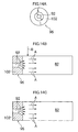
- a usable form includes such various forms, so far as a headspace part 116 is formed above the gas-liquid interface 119 when a reaction liquid LM flows through the gas-liquid separation pipe 118, as an ellipsoid form as shown in Fig. 4 and a square form in Fig. 5, and further a box form.
- the most preferable form of a gas-liquid separation pipe 118 is an ellipsoid form, particularly having the same shape in a lower circle part of the gas-liquid separation pipe 118 with a lower semicircle of the pipe 14, the secondly preferable form of the gas-liquid separation pipe 118 is a cylindrical form, and the thirdly preferable form of the gas-liquid separation pipe 118 is a square form.
- the gas-liquid separation pipe 118 has preferably 1.5 times or larger volume per unit length (in the longitudinal direction of a reaction liquid LM) than the volume per unit length of a pipe 14.
- a gas-liquid interface 119 is formed between a liquid phase part in which the reaction liquid LM flows, and a gas phase part of a headspace part 116 in which a byproduct gas released from the reaction liquid LM is accumulated.
- the byproduct gas generated with proceeding of a reaction in the pipe 14 changes into bubbles in a reaction liquid, and moves up to the surface, so that when the reaction liquid LM passes through the gas-liquid separation pipe 118, the byproduct gas is floatation-separated into a headspace part 116 from a gas-liquid interface 119.
- the gas-liquid separation pipe 118 preferably has enough length L in a flowing direction of the reaction liquid, for the bubbles generated in the bottom part of the gas-liquid separation pipe 118, to rise to the surface and be released into the headspace. part, after the reaction liquid LM flows into the gas-liquid separation pipe 118 and before the reaction liquid flows out from the gas-liquid separation pipe.
- a pressure adjustment device 120 mainly comprises a pressure sensor 122 for measuring the pressure of a headspace part 116, a vent pipe 126 with a valve 124 for exhausting a byproduct gas accumulated in the headspace part 116, and a control part 128 for opening and closing the valve 124 on the basis of the measured value by the pressure sensor 122.
- a valve 124 used for a pressure adjustment device 120 preferably opens and closes both at a response speed of 10 milliseconds or shorter, and further preferably of 5 milliseconds or shorter.
- a servo valve is available. Thereby, when the measured value of the pressure sensor 122 varies from a predetermined pressure set value, the valve 124 opens or closes at a very high opening or closing speed, which can eliminate fluctuation in the pressure of a headspace part 116.
- a resistor (not shown) for decreasing a discharge rate of a byproduct gas may be installed at some point of the vent pipe 126 including the valve 124, to make pressure control easy.
- the resistor an orifice or a filter can be preferably used.
- a purging pipe 117 provided with the valve 117A is connected in order to purge air with an inert gas such as gaseous nitrogen into the gas-liquid separation pipe 118.
- the purging pipe 117 feeds an inert gas, when the reaction is anaerobic, or a byproduct gas generated by the reaction is a dangerous gas in the presence of oxygen, such as hydrogen gas, into the gas-liquid separation pipe 118 through itself in order to purge air and fill the gas-liquid separation pipe 118 with the inert gas.
- the purging pipe 117 can be used for the case of feeding the inert gas into the gas-liquid separation pipe 118 to previously raise the pressure in the gas-liquid separation pipe 118 into a higher pressure than ambient pressure, and then sending a reaction liquid LM into the gas-liquid separation pipe 118 to form a gas-liquid interface at an appropriate position in the gas-liquid separation pipe 118 from the beginning.
- the appropriate position of the gas-liquid interface is the position, for instance, where the cross-sectional area of a reaction liquid flowing through the gas-liquid separation pipe 118 becomes approximately equal to the cross-sectional area of the reaction liquid flowing through the pipe 14. It can be determined by a preliminary test or calculation of what previous pressure in a headspace part 116 forms the appropriate position of the gas-liquid interface.
- a gas-liquid separation unit 16 configured as described above can continuously and efficiently remove a byproduct gas only by passing a reaction liquid LM in a gas-liquid separation pipe 118 where the pressure of a headspace part 116 is kept constant.
- an apparatus 10 for continuously producing metal microparticles can be easily constituted only by installing the gas-liquid separation unit 16 in a midway of the pipe 14 which connects a mixing unit 12 with a recovery tank 23.
- the flow of the reaction liquid LM in the gas-liquid separation pipe 118 can be stabilized by keeping the pressure of the headspace part 116 constant, the flow of a reaction liquid LM flowing through a pipe 14 can be stabilized in the pipes 14 in front and in the rear of the gas-liquid separation unit 16.
- a mixing unit used in the present invention is preferably a type of immediately discharging the reaction liquid LM which can be instantly mixed in a mixing field and reacts right after mixture, without making it stay in the mixing field, in the view point of forming metal microparticles which has fine sizes and preferable monodispersibility, and a preferably usable mixing unit includes a high-speed stirring and mixing type, a narrow-gap mixing type and a high pressure mixing type.
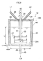
- Fig. 6 is a sectional view of a mixing unit 12 of a high-speed stirring and mixing type.
- a mixing unit 12 is formed into a cylindrical vessel shape and comprises a narrow mixing vessel 30 having a retention time of 10 seconds or shorter, and a high-speed stirrer 32 installed therein.
- the high-speed stirrer 32 has the top part of its vertical rotating shaft 34 rotatably supported on the closure plate 36 of the mixing vessel 30 through a bearing 38, and to the upper end of the rotating shaft 34, a motor 40 fixed to the pedestal which is not shown is connected.
- two stages of edge turbulent type stirring blades 42 in the top and the bottom are installed so as to be immersed in a liquid.
- the spacing between the stirring blades 42 is preferably in a range of 1.0 d to 0.5 d, when the diameter of the stirring blade 42 is defined as d.
- the depth of the static liquid in the mixing vessel 30 is preferably in a range of 2 d to 3 d.
- the type of the stirring blade 42 is shown as an edge turbine type, but a dissolver type, a paddle type, a propeller type and a flat disk type can be used, and further a turbine type and disc turbine type can be also used. Even when any type of a stirring blade 42 is used, the high speed stirrer 32 has such a structure as to make peripheral velocity at the top of the stirring blade 42 to be preferably 5 m/second or longer, and further preferably 10 m/second or longer.
- a jacket 44 through which a heating medium having comparatively large heat capacity, such as water and oil, is wound, and a heat medium inlet 44A and a heat medium water outlet 44B of the jacket 44 are connected to a heat medium-feeding device which is not shown.
- a first solution L1 is supplied from the previously described first preparation tank 22 through a feed pipe 26, and a second solution L2 is supplied from the second preparation tank 24 through a feed pipe 28.
- the top of each of feed pipes 26 and 28 penetrates the top board 36 of the mixing vessel 30, and is extended preferably to the vicinity of a liquid level along a rotating shaft 34 of a high-speed stirrer 32.
- an outlet duct 46 for a reaction liquid LM is connected to the base plate 30A of the mixing vessel 30, and a valve 48 is installed on the way of the outlet duct 46.
- a mixing vessel 30 receives a predetermined quantity of a first solution L1 prepared in a first preparation tank 22 and supplied through a feed pipe 26, and then a high-speed stirrer 32 starts high-speed stirring so as to make a circumferential speed at the tip of the stirring blade 42 to be 5 m/second or longer, and preferably 10 m/second or longer. Subsequently, a second solution L2 is added from a second preparation tank 24 to the first solution L1 in the mixing vessel 30 through a feed pipe 28.
- the temperatures of the solutions L1 and L2 and the temperature in the mixing vessel 30 are set to predetermined temperatures suitable for an early reaction by which metal microparticles with a crystal structure are formed.
- the first solution L1 in the mixing vessel 30 has an extremely strong slewing flow formed into a V-shape around a rotating shaft 34 which convolutes the solution from a liquid level toward the bottom, and then the second solution L2 added to the vicinity of the rotating shaft 34 is instantly convoluted into the first solution L1 by the slewing flow forming a V-shape, and is uniformly dispersed in the whole first solution L1 in the mixing vessel 30.
- the reaction liquid LM is mixed and reacts in the mixing vessel 30, and is promptly discharged from an exhaust pipe 46.
- the residence time in the mixing vessel 30 is preferably 10 seconds or shorter. Thereby, the metal microparticles having fine sizes and preferable monodispersibility are formed.
- the second solution L2 may be charged in the mixing vessel 30 at first, and then the first solution L1 may be charged.
- Fig. 7 shows another aspect of a high-speed stirring and mixing type of a mixing unit 12.
- a narrow mixing vessel 55 which gives a solution a residence time of 10 seconds or shorter, is separated into two mixing chambers 54 and 56 with a partition plate 52 having a communicating port 50.
- stirring blades 58 and 60 are respectively installed and stir the solution at high speed with motors 59 and 61 so as to make circumferential speeds at the tips to be 5 m/second or higher, and preferably 10 m/second or higher.
- first and second solutions L1 and L2 are supplied to one mixing chamber 54 at first, and are stirred and mixed with the stirring blade 58 at high speed, and then, the mixed solution flows into another mixing chamber 56 through the communicating port 50, is further stirred and mixed at high speed with the stirring blade 60, and then is discharged.
- the mixing unit 12 of a high-speed stirring and mixing type in Fig. 7 because a mixed liquid immediately moves to each of the mixing chambers 54 and 56 without staying, the first and second solutions L1 and L2 are instantly mixed and the reaction liquid can be immediately discharged. Thereby, metal microparticles having fine sizes and preferable monodispersibility are formed.
- a mixing unit 12 for conducting a high-speed stirring method is not limited to the mixing units in Figs. 6 and 7, but has only to have a structure which can accommodate first and second solutions L1 and L2 in a mixing vessel 30, mix and react them with a liquid-phase reaction method, and make a circumferential speed at the tip of a stirring blade 42 to be 5 m/second or higher.
- Fig. 8 is a sectional view of a mixing unit 12 of a narrow-gap mixing type.
- a mixing unit 12 has a cylindrical rotatable drum 64 with a slightly smaller diameter than the minor diameter of a mixing vessel 62, installed in the vertical mixing vessel 62 with the shape of a cylindrical vessel having the top and bottom sealed.
- the rotatable drum 64 has an upright rotating shaft 66 along a rotation center S, and the upper and lower parts of the rotating shaft 66 are rotatably supported on the top board 62A and the bottom plate 62B of the mixing vessel 62 through bearings 68 and 68.
- a motor 70 fixed to the pedestal which is not shown, is connected.
- a ring-shaped narrow-gap 72 is formed between the internal circumferential wall face of a mixing vessel 62 and the outer circumferential face of a rotatable drum 64.
- the ring-shaped narrow-gap 72 can be formed by such a setting that when a distance D1 between a rotation center S and a top of the rotatable drum 64 is supposed to be 1, a distance D2 between the rotation center S of the rotatable drum 64 and the closest inner wall of the mixing vessel 62 is in a range of 1.001 to 1.200.
- a supply port 74 for a first solution L1 and a supply port 76 of a second solution L2 are formed, and each of the supply ports 74 and 76 is respectively connected to each of feed pipes 26 and 28.
- an exhaust port 75 for a reaction liquid LM is formed and connected to a pipe 14.
- width of a gap is from 10 ⁇ m to 10mm. More preferably, width of a gap is from 0.1mm to 5mm.
- first and second solutions L1 and L2 are supplied into the narrow-gap 72 of a mixing vessel 62, under an appropriate mixture reaction temperature condition, in a state that a rotatable drum 64 rotates at such an ultra-high speed as to make a circumferential speed at the tip (the top circumferential position) to be 5 m/second or higher, and preferably 10 m/second or higher.
- the small distance when the above described distance D2 is too small as smaller than 1.001, the small distance causes ununiformity of a shearing force due to the effect of surface roughness on the internal circumferential wall face of the mixing vessel 62 and the outer circumferential face of the rotatable drum 64, and thereby makes the monodispersibility of the formed metal microparticles inferior.
- the distance D2 when the distance D2 is too long as larger than 1.200, the large distance causes a small shearing force given to the solutions L1 and L2, and makes the particle sizes of the formed metal microparticles easily large, and also the monodispersibility easily inferior.
- Fig. 9 is a sectional view showing another aspect of the mixing unit 12 of a narrow-gap mixing type, and the same reference numeral will be put on the same member as in Fig. 8 for explanation.
- a mixing unit 12 is composed so as to make the inner wall diameter of a mixing vessel 62 get smaller with respect to the major diameter of a rotatable drum 64 as going up to the upper end from the lower end of a mixing vessel 62, and a narrow-gap 72 narrowed as going up to the upper end from the lower end of the mixing vessel 62.
- first and second solutions L1 and L2 supplied into the narrow-gap 72 get a faster flow rate as the solutions move to the upper end from the lower end of the mixing vessel 62, so that the shearing force given to the first and second solutions L1 and L2 can be slowly increased.
- a distance D 1 between a center and a top of a rotatable drum 64, and a distance D2 from the rotation center S of the rotatable drum 64 to the closest inner wall of the mixing vessel 62 are the dimension at the upper end position of the mixing vessel 62 as shown in Fig. 9.
- Fig. 10 is a sectional view which shows further different aspect of the mixing unit 12 of a narrow-gap mixing type, and the same reference numeral is put on the same member as in Fig. 8 for explanation.
- a mixing unit 12 has a plurality of disc-shaped flat disks 80, in place of a rotatable drum 64 arranged around a rotating shaft 66 at a predetermined spacing.
- a distance between adjacent flat disks 80 is preferably equal to the narrow-gap 72 which is formed between the outer peripheral surface of the flat disk 80 and the internal circumferential wall face of a mixing vessel 62.
- the mixing unit 12 of a narrow-gap mixing type is not limited to Figs. 8, 9 and 10, but has only to be a unit having the narrow-gap 72 formed between the inner wall of a mixing vessel 62 and the stirring members 64 and 80 which rotate at a high speed, and having such a setting that when a distance between the rotation center S and the top of the stirring members 64 and 80 is supposed to be 1, a distance between the rotation center S of the stirring members 64 and 80 and the closest inner wall is in a range of 1.001 to 1.200, in order to form the narrow-gap 72, and to have such a structure as to supply first and second solutions L1 and L2 into the narrow-gap 72 and mix them and discharge a mixed reaction liquid LM from the narrow-gap 72.
- any of a one-jet type, a T-shaped type, a Y-shaped type and a two-jet facing type can be preferably used.
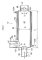
- Fig. 11 is a sectional view showing a concept of a one-jet type mixing unit 12.
- a mixing unit 12 comprises a mixing vessel 84 having a cylindrical mixing chamber 82 (a mixing field) formed therein for mixing and reacting first and second solutions L1 and L2 therein, a first conduit 86 for introducing the first solution L1 into the mixing chamber 82, which is connected to an opening at one-end side of the mixing vessel 84, and an outlet duct 88 for discharging a reaction liquid mixed and reacted in the mixing chamber 82, which is connected to the other opening at the other end side of the mixing vessel 84.
- a second conduit 90 for introducing the second solution L2 into the mixing chamber 82 is connected to the part on the peripheral surface of the mixing vessel 84 and close to the outlet of the first conduit 86.
- a first orifice 92 and a second orifice 94 are respectively formed, and thereby, in the first conduits 86 and the second conduits 90, a first nozzle 96 and a second nozzle 98 are formed so as to jet a turbulent liquid.
- the first solution L1 is introduced from the first conduit 86
- the second solution L2 is introduced from the second conduit 90, but each liquid can be introduced from a reverse conduit.
- an outlet duct 88 may be connected to the side part of the mixing vessel 84, so far as the side part is close to the other end side of the mixing vessel 84.
- a mixture reaction temperature is preferably set appropriately to a predetermined temperature suitable for early reaction according to the types of first and second solutions L1 and L2.
- a plurality of nozzle positions for sprouting the plurality of solutions L1 may be arranged on the peripheral side of a mixing vessel 84, or alternatively, a plurality of solutions L1 may be sequentially sprouted from one nozzle position. Consequently, a nozzle for the straight high-pressure jet flow is basically one, but there may be a plurality of nozzles for an orthogonal flow perpendicular to the straight flow.
- the methods well-known as working methods for precisely boring an exhaust nozzle with a diameter of about 100 ⁇ m in the orifice materials 102 such as metal, ceramic and glass can be preferably used.
- the well-known methods include micro cutting working, micro grinding, blasting, micro electric discharge machining, a LIGA method, laser beam machining and SPM working.
- a material for the orifice material 102 has preferably a superior workability and has hardness close to diamond.
- the preferably usable materials include, aside from diamond, various metals and metal alloys which are hardened by quenching, nitriding, sintering or the like.
- ceramic can be also preferably used, because of having high hardness and superior workability to diamond.
- a throttle structure of first and second nozzles 96 and 98 is described by taking an orifice as an example, but so far as the throttle structure has a function for jetting a turbulent liquid, any other device can be used without being limited to the orifice.
- a first conduit 86 and a second conduit 90 have a compressing device which is not shown, through which a first solution L1 and a second solution L2 are compressed and supplied to the first and second nozzles 96 and 98.
- the pressure for sprouting the solution from the second nozzle 98 into a mixing chamber 82 is controlled smaller than the pressure of the high-pressure jet flow which jets out from the first nozzle 96 to the mixing chamber 82.
- the compressing device for applying a high pressure to a liquid various devices are known and any one can be used, but a reciprocating pump such as a plunger pump and a booster pump are preferably used, because they are comparatively available and inexpensive.
- a rotary pump cannot generate such a high pressure as the reciprocating pump, a high-pressure generation type of the rotary pump may be used.
- a first solution L1 is sprouted to a mixing chamber 82 from a first nozzle 96 in the form of a jet flow at a high pressure of 1 MPa or higher and a turbulent flow with the Reynolds number of 10,000 or more when flowing into the mixing chamber 82, and a second solution L2 having a lower pressure than the first solution L1 is sprouted from a second nozzle 98 to the mixing chamber 82, as a cross flow almost perpendicular to the first solution L1.
- the second solution L2 even if the second solution L2 is not perpendicular to the first solution L1 precisely at an angle of 90 degree, the second solution L2 has only to contain a perpendicular velocity vector component as the main component.
- the mixture reaction utilizes high eddy viscosity generated when the first solution L1 of a turbulent jet flow with a high speed and a high pressure convolutes the second solution L2 sprouted from an almost perpendicular direction to the first solution L1 so as to be accompanied by the second solution L2, and the first and second solutions L1 and L2 are mixed to obtain a high mixing efficiency, so that the above described mixing chamber 82, first and second nozzles 96 and 98 and exhaust pipe 88 of the mixing unit 12 are formed so as to have the relation described below.
- a cylinder diameter D 1 is formed so as to be larger than an orifice diameter D2 of a first nozzle 96 and an orifice diameter D3 of a second nozzle 98. Because the eddy viscosity particularly produced by a first solution L1 of a straight flow A is important for increasing a mixing efficiency, the dimension ratio of the cylinder diameter D 1 of the mixing chamber 82 to the orifice diameter D2 of the first nozzle 96 is preferably in a range of 1.1 to 50, and further preferably 1.1 to 20.
- the pressure of the cross flow B is preferably decreased below the pressure of the straight flow A to make a spouting speed of flow equal to that of the straight flow A or less.
- the ratio of the spouting speed of the cross flow B to that of the straight flow A is preferably 0.05 to 0.4, and further preferably 0.1 to 0.3.
- a cross flow B is necessary to be sprouted to a mixing chamber 82 before the position in which eddy viscosity C formed by the straight flow A which is sprouted from the first nozzle 96 with a small diameter to the mixing chamber 82 having a larger diameter than it, is maximized, and consequently a second nozzle 98 is necessary to be placed at a position between the first nozzle 96 and the position of the maximum eddy viscosity C. Accordingly, it is necessary to know the position in which the eddy viscosity C is maximized.
- the position in the mixing chamber 82, in which the eddy viscosity C is maximized can be grasped by previously performing a simulating calculation with the use of the numerical analysis software RFLOW made by Rflow Co., Ltd., which has been already on the market as a flow analysis software in Japan and is known well as the flow analysis software.
- the position of allowing the eddy viscosity C maximized is not a pinpoint but has a region, so that the position of allowing the eddy viscosity C maximized has only to be determined as a point P of an almost central position of the eddy viscosity C.
- the second nozzle 98 is preferably positioned in the front of the point P, but the position of the second nozzle 98 is more preferably determined so that the crossing flow B can be sprouted at an early stage of forming the eddy viscosity C.
- the central point P of the region where eddy viscosity C appears has a relationship to the flow rate of a straight flow A, and approximately matches the position in which the maximum flow rate (normally a flow rate at the first nozzle position) of the straight flow A is lowered to 1/10. Accordingly, by calculating the position in which the maximum flow rate of the straight flow A is lowered to 1/10, the position of a second nozzle 98 can be determined so that the crossing flow B can be sprouted to the front of the point. Then, it is not necessary to calculate the point P.
- the length L (see Fig. 1) of the mixing chamber 82 is necessary to be secured, but too long length makes a reaction liquid LM easy to stay or reversely flow in the mixing chamber 82 and adversely affects the atomization and the monodispersibility of metal microparticles. Consequently, the length L of the mixing chamber 82 is preferably 2 to 5 times, and further preferably 2 to 3 times of a distance between the first nozzle 96 and the point P which is the position of allowing the eddy viscosity C maximized.
- the shape of a spouted flow from a first nozzle 96 to a mixing chamber 82 is controlled by a first orifice 92 installed in the first nozzle 96, and affects a mixing performance.
- the shape of a spouted flow is preferably selected among a filar shape, a cone shape, a slit shape and a deltaic shape, through appropriately selecting the first orifice 92 which forms the above shapes.
- a straight flow A and a crossing flow B are necessary to be sprouted so as to make eddy viscosity C instantly maximized in as narrow an area as possible, and then such a first orifice 92 as to form a filar shape of a sprouting flow is preferable.
- the straight flow A and the crossing flow B are preferably sprouted so as to make the eddy viscosity C maximized in as wide an area as possible, to increase an accompanied interfacial area produced by the straight flow A, and thus in this case, the first orifice 92 which forms a thin-film shape of a sprouting flow is preferably employed. Furthermore, in the case of an intermediate reaction rate between an extremely low reaction rate of a millisecond order and a comparably low reaction rate, the first orifice 92 which forms a cone shape of a sprouting flow is preferable.
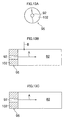
- Figs. 13A to 16C show the first orifice 92 for forming each sprouting flow with a filar shape, a cone shape, a slit shape and a deltaic shape.
- Fig. A show a figure of viewing an orifice from a top side
- Fig. B shows a longitudinal section of an orifice
- Fig. C shows a cross section of an orifice.
- Figs. 13A to 13C show the shape of a first orifice 92 for sprouting a filar straight flow A to a mixing chamber 82, which is formed into a filar shape.
- Figs. 14A to 14C show a shape of the first orifice 92 for sprouting the cone-shape of the straight flow A to the mixing chamber 82, and the straight flow A is formed into the wrapper-tube shape of which the front end is opened.
- Figs. 15A to 15C show the first orifice 92 for sprouting a thin straight flow A to the mixing chamber 82, which is formed into the shape of a rectangular slit.
- Figs. 16A to 16C show the first orifice 92 for sprouting a deltaic thin straight flow A to the mixing chamber 82, which is formed into a deltaic shape having the diameter of the front end expanded.
- the mixing unit 12 of a one-jet mixing type is not limited to Fig. 11 described above, but any type can be used so far as it employs the static mixing unit which sprouts out first and second solutions L1 and L2 from each nozzle to a mixing field having a larger diameter than the diameter of the nozzle to mix and react the solutions, and discharges the mixed reaction liquid from an exhaust port having a smaller diameter than that of the above described mixing field, sprouts out at least one of the solutions L1 and L2 into a mixing field in the form of a jet flow at a high pressure of 1 MPa or higher and a turbulent flow with the Reynolds number of 10,000 or more when flowing into the mixing field, and can add the rest solution to the front of the position at which the eddy viscosity formed by the high-pressure jet flow in a flow direction, is maximized, with a lower pressure than that of the above described high-pressure jet flow.
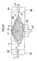
- Figs. 17 and 18 are sectional views of T-shaped and Y-shaped mixing units 12, and Fig. 17 shows a T-shaped pipe and Fig. 18 shows a Y-shaped pipe.
- a T-shaped pipe and a Y-shaped pipe instantly mix first and second solutions L1 and L2 at the intersection (a mixing field) of extremely thin pipes of themselves by colliding both solutions in the form of a jet flow with a high pressure of 1 MPa or higher, and discharge the reacted reaction solution from an exhaust pipe in a short time.
- the T-shaped type and the Y-shaped type sprout a first solution L1 from a first adding pipe 106 to the mixing field 108 in the jet flow with a high pressure of 1 MPa or higher, and the second solution L2 from a second adding pipe 110 to the mixing field 108 in the jet flow with a high pressure of 1 MPa or higher, to collide both solutions; and then the reaction liquid LM which has been mixed by the energy of collision and reacted, is discharged from an exhaust pipe 112 in a short time.
- the pressures of the first and second solutions L1 and L2 may be equal or different from each other, so far as they are 1 MPa or higher.
- a jacket 114 is wound to control a mixture reaction temperature of the first and second solutions L1 and L2 in the mixing field 108.
- a numeral 114A in Figs. 17 and 18 denotes an inlet for a heating medium of the jacket 114
- a numeral 114B denotes an outlet for the heating medium.
- first and second solutions L1 and L2 are so instantly and effectively mixed and react under an appropriate mixture reaction temperature condition, and the reacted liquid is so immediately discharged from an exhaust pipe 112 that metal microparticles having fine sizes and adequate monodispersibility can be formed.
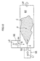
- Fig. 19 shows a mixing method adding a concept of eddy viscosity to a T-shaped type, where the same member with the member in Fig. 11 is marked with the same numeral for convenience of explanation.
- the mixing method comprises sprouting first and second solutions L1 and L2 from a counter direction in the form of a jet flow with a high pressure of 1 MPa or higher, to a mixing chamber 82 (a mixing field) having a diameter larger than that of a nozzle for sprouting the solutions L1 and L2, to collide them, mixing them by taking the advantage of eddy viscosity produced in both solutions, and discharging the reacted liquid LM from an exhaust pipe 88 having a smaller diameter than the mixing chamber 82 has.
- a mixing unit 12 in Fig. 19 has a first conduit 86 for introducing a first solution L1 into a mixing chamber 82 connected to the one-end opening of a mixing vessel 84 having a cylindrical mixing chamber 82 for mixing and reacting the first solution L1 and a second solutions L2, formed therein; the second conduit 90 for introducing the second solution L2 into the mixing chamber 82 connected to the other-end opening; and an exhaust pipe 88 for discharging the reacted liquid LM which has been mixed and reacted in the mixing chamber 82, from the mixing chamber 82, connected to the central opening of the mixing vessel 84.
- first and second orifices 92 and 94 are respectively installed, and thereby first and second nozzles 96 and 98 for jetting turbulent straight flows A1 and A2 are formed in the first and second conduits 86 and 90.
- first and second orifices 92 and 94 are respectively installed, and thereby first and second nozzles 96 and 98 for jetting turbulent straight flows A1 and A2 are formed in the first and second conduits 86 and 90.
- a jacket 100 is wound around the periphery of a mixing vessel 84 to control a mixture reaction temperature of first and second solutions L1 and L2 in a mixing vessel 84, as having been described in Fig. 11.
- the two counter-jets type has the similar cylindrical diameter D1 of a mixing chamber 82, the similar orifice diameter D2 of a first nozzle 96, the similar orifice diameter D3 of a second nozzle 98, and the similar dimension relations thereof to the one-jet type; and has a similar method for forming first and second orifices 92 and 94, and material of an orifice material 102 and a compressing device to those described in the one-jet type.
- the shapes of the straight flows A1 and A2 as have been described in the one-jet type, can be formed into each shape of a sprouting flow of a filar shape, a cone shape, a slit shape and a deltaic shape.
- first and second solutions L1 and L2 are sprouted in the form of a jet flow with a high pressure of 1 MPa or higher from both one end and the other end of a mixing chamber 82, through first and second nozzles 96 and 98, and are collided as counter turbulent straight flows A1 and A2 in the mixing chamber 82.
- the solutions L1 and L2 are instantly mixed under an appropriate mixture reaction temperature condition, and the reacted reaction liquid LM is immediately discharged from an exhaust pipe 88.
- metal microparticles having fine sizes and adequate monodispersibility can be formed.
- a mixture reaction acquires a high mixing efficiency, when the positions to obtain maximum eddy viscosities C and D formed in a mixing chamber 82 by respective two high-speed turbulent straight counter-flows A1 and A2, are overlapped so as to make the eddy viscosity at an area E as large as possible.
- the straight flows A1 and A2 do not collide with each other right after being sprouted into the mixing chamber 82, but collide at the position where the two eddy viscosities C and D formed in the mixing chamber 82 by the straight flows A1 and A2 make the eddy viscosity at the overlapped area E as large as possible.
- it is preferable to adequately set a separation distance L see Fig.
- the separation distance L between the first nozzle 96 and the second nozzle 98 is desirably determined as a total value of a distance between the first nozzle 96 and a point P1 and a distance between the second nozzle 98 and a point P2 when the point P1 is matched with the point P2, where the points P1 and P2 are defined as the positions of the approximately central parts in the obtained maximum eddy viscosities C and D.
- the points P1 and P2 are defined as the positions of the approximately central parts in the obtained maximum eddy viscosities C and D.
- the points P1 and P2 for allowing the eddy viscosities C and D maximized by straight flows A1 and A2 have a relation with the flow rates of the straight slows A 1 and A2, and approximately match the positions for allowing the flow rates of the straight flows A 1 and A2 lowered to 1/10 of the maximum flow rates (normally flow rates of the first or second nozzle positions). Accordingly, by calculating such positions as to allow the flow rates of the straight flows A1 and A2 lowered to 1/10 of the maximum flow rates, the points P1 and P2 may be grasped.
- overlapping of the eddy viscosities C and D at the positions of allowing the eddy viscosities C and D maximized has an effect of improving a mixture reaction performance through increasing a contacting efficiency on a liquid-liquid interface of the straight flows A1 and A2, and besides, exerts the effect of controlling the heat generation caused by liquid-liquid friction due to the collision of the straight flows A1 with the straight flow A2.
- the above described apparatus 10 for producing metal microparticles incorporates such a gas-liquid separation unit 16 according to the present invention on the way of pipe 14 for making a reaction liquid LM flow therein that a byproduct gas generated by a reaction changes into bubbles, moves upward in a reaction liquid and is continuously released from a gas-liquid interface 119 in a gas-liquid separation pipe 118 into a headspace part 116. While the gas is removed in the gas-liquid separation pipe 118, the pressure of the headspace part 116 is controlled so as to be constant by a pressure adjustment device 120, and consequently the flow of the reaction liquid LM does not become unstable in the pipes 14 in front and in the rear of the gas-liquid separation pipe 118.
- a gas-liquid separation unit 16 according to the present invention is suitable for degassing in a flow reaction process which performs such a reaction as to generate a byproduct gas while a reaction liquid LM flows, and particularly for the process of continuously producing metal microparticles contained in a magnetic layer of a magnetic recording medium. Because when the gas-liquid separation unit 16 according to the present invention is employed in the process, the reaction accompanied by the generation of a byproduct gas can be so uniformized that the monodispersibility of the produced metal microparticles can be improved. In addition, because it is considered that the equilibrium of the reaction moves to a reaction acceleration side by continuous degassing, it improves the reactivity, enables a prompt reaction, and consequently can minimize the sizes of metal microparticles.
- the gas-liquid separation unit 16 can effectively remove the byproduct gas in the flow of continuous treatment, thereby improves control accuracy for a solution temperature, and consequently reduces the size of the produced microparticles and improves the monodispersibility thereof.
- the production process of metal microparticles incorporates a gas-liquid separation unit 16 according to the present invention therein, it can reliably continuously produce the metal microparticles, and as a result, it can eliminate batch-to-batch variations in the quality of metal microparticles which occur in a conventional batch-type production process. Thereby, the metal microparticles having small particle sizes, adequate dispersibility and a constant quality, can be stably produced.
- the gas-liquid separation unit 16 enables a reaction to be conducted in a flow of a continuous process, and can use the whole pipe 14 for allowing a reaction liquid LM to flow as a temperature control line for controlling a reaction temperature, to make the reaction temperature control easy compared to the reaction in a conventional batch-type process.
- the apparatus may have purging devices for sending an inert gas such as nitrogen (N2) installed in first and second preparation tanks 22 and 24 and a recovery tank 23 as well.
- N2 nitrogen
- a reversed micelle solution (L1) and a reversed micelle solution (L2) were instantly mixed with the use of any one of mixing units 12 in Figs. 6 to 20.
- the reaction liquid LM was taken out from the mixing unit 12 simultaneously with the end of mixing, was passed in a gas-liquid separation unit 16 where a byproduct gas was removed, and in 10 minutes, was collected into a recovery tank 23.
- the metal microparticle obtained thereby is called a present invention method sample.
- both of a conventional method sample and a present invention method sample were then heated to 50°C and were aged for 60 minutes while being stirred by a magnetic stirrer; and to the solution, subsequently, 2 ml of oleic acid (made by Wako Pure Chemical Industries, Ltd.) was added; and the resultant solution was mixed and cooled to a room temperature, and then was taken out into the atmosphere.
- a conventional method sample and a present invention method sample were then heated to 50°C and were aged for 60 minutes while being stirred by a magnetic stirrer; and to the solution, subsequently, 2 ml of oleic acid (made by Wako Pure Chemical Industries, Ltd.) was added; and the resultant solution was mixed and cooled to a room temperature, and then was taken out into the atmosphere.
- the mixed liquid of 100 ml of H 2 O (previously deoxygenated into 0.1 mg/l or less of dissolved oxygen) with 100 ml of methanol was added to the above solution to separate it into a water phase and an oil phase.
- oil phase metal nanoparticles in a dispersed state were obtained.
- the oil phase was washed five times with a mixed liquid of 600 ml of H 2 O (previously deoxygenated into 0.1 mg/l or less of dissolved oxygen) and 200 ml of methanol. Then, 1,100 ml of methanol was added to flocculate and settle the metal nanoparticles.
- the supernatant liquid was removed, 20 ml of heptane (made by Wako Pure Chemical Industries, Ltd.) was added to redisperse the metal nanoparticles, and 100 ml of methanol was added to sediment the metal nanoparticles. The treatment was repeated three times, and finally 5 ml of octane (made by Wako Pure Chemical Industries, Ltd.) was added to obtain a dispersion containing metal nanoparticles of FePt dispersed in a liquid having a mass ratio (water/surface active agent) of water to a surface active agent in the value of 2.
- the metal nanoparticles obtained by a conventional method and a method according to the present invention were subjected to the measurement of its yield, its composition, its volume, its average particle diameter and particle size distribution (coefficient of variation), and its coercive force.
- the composition and the yield were measured with ICP spectrochemical analysis (inductively coupled plasma atomic emission spectrochemical analysis), and the volume, the average particle diameter and the particle size distribution were determined by statistically processing the values obtained through measuring the particle diameters of the particles photographed with a TEM.
- the coercive force was measured with the use of a high-sensitive magnetization vector measuring instrument made by Toei Industry CO., LTD.
- the metal nanoparticles were prepared and used for the measurement, by means of collecting the metal nanoparticles from a prepared dispersion containing the metal nanoparticles, thoroughly drying them and heating them at 550°C for 30 minutes in an electric furnace.
- the measured results of the metal nanoparticles obtained in the embodiment 1 by a conventional method and a method according to the present invention are shown in Table 1.
- the metal nanoparticles obtained by a method according to the present invention showed smaller sizes and superior monodispersibility, compared to those of the metal nanoparticles obtained by a conventional method.
- a method according to the present invention provided a higher percentage of a Pt content than a conventional method did.
- the metal nanoparticles obtained by a conventional method and a method according to the present invention were subjected to the same measurement as in the embodiment 1, of the yield, the composition, the volume, the average particle diameter and particle size distribution (coefficient of variation), and the coercive force. These measuring methods are the same methods as used in the embodiment 1.
- the measured results of the metal nanoparticles obtained in the embodiment 2 by a conventional method and a method according to the present invention are shown in Table 2.
- the metal nanoparticles obtained by a conventional method and a method according to the present invention were subjected to the same measurement as in the embodiment 1, of the yield, the composition, the volume, the average particle diameter and particle size distribution (coefficient of variation), and the coercive force. These measuring methods are the same methods as used in the embodiment 1.
- the measured results of the metal nanoparticles obtained in the embodiment 3 by a conventional method and a method according to the present invention are shown in Table 3.
Landscapes
- Chemical & Material Sciences (AREA)
- Chemical Kinetics & Catalysis (AREA)
- Physical Or Chemical Processes And Apparatus (AREA)
- Degasification And Air Bubble Elimination (AREA)
- Manufacture Of Metal Powder And Suspensions Thereof (AREA)
Applications Claiming Priority (2)
| Application Number | Priority Date | Filing Date | Title |
|---|---|---|---|
| JP2003368896 | 2003-10-29 | ||
| JP2003368896A JP2005131492A (ja) | 2003-10-29 | 2003-10-29 | 気液分離方法及び装置 |
Publications (1)
| Publication Number | Publication Date |
|---|---|
| EP1527804A1 true EP1527804A1 (de) | 2005-05-04 |
Family
ID=34420163
Family Applications (1)
| Application Number | Title | Priority Date | Filing Date |
|---|---|---|---|
| EP04025768A Ceased EP1527804A1 (de) | 2003-10-29 | 2004-10-29 | Verfahren und Vorrichtung zur Gas-Flüssigkeitstrennung |
Country Status (3)
| Country | Link |
|---|---|
| US (1) | US7384451B2 (de) |
| EP (1) | EP1527804A1 (de) |
| JP (1) | JP2005131492A (de) |
Cited By (2)
| Publication number | Priority date | Publication date | Assignee | Title |
|---|---|---|---|---|
| WO2011153048A1 (en) | 2010-05-31 | 2011-12-08 | Corning Incorporated | Microreactor device having an essentially vertical or inclined upper portion comprising means for collection and removal of gas formed in situ during a liquid-medium reaction and method |
| CN101868316B (zh) * | 2007-09-27 | 2012-06-20 | M技术株式会社 | 磁性体微粒的制造方法、由此得到的磁性体微粒、及磁性流体、磁性体制品的制造方法 |
Families Citing this family (17)
| Publication number | Priority date | Publication date | Assignee | Title |
|---|---|---|---|---|
| GB0120835D0 (en) | 2001-08-28 | 2001-10-17 | Smithkline Beecham Plc | Process |
| JP4381260B2 (ja) * | 2004-08-31 | 2009-12-09 | 愛知機械工業株式会社 | 自動車 |
| TW200702035A (en) * | 2005-03-07 | 2007-01-16 | Univ Okayama Nat Univ Corp | Deaerator and deaerating method |
| US8148276B2 (en) | 2005-11-28 | 2012-04-03 | University Of Hawaii | Three-dimensionally reinforced multifunctional nanocomposites |
| US7658870B2 (en) * | 2005-12-20 | 2010-02-09 | University Of Hawaii | Polymer matrix composites with nano-scale reinforcements |
| JP5216996B2 (ja) * | 2006-02-15 | 2013-06-19 | 国立大学法人 岡山大学 | 脱気・溶解装置 |
| GB0706908D0 (en) * | 2007-04-10 | 2007-05-16 | Nitech Solutions Ltd | Plug flow tubular mixing apparatus and method |
| WO2009008390A1 (ja) * | 2007-07-06 | 2009-01-15 | M.Technique Co., Ltd. | 金属微粒子の製造方法及びその金属微粒子を含む金属コロイド溶液 |
| KR101321911B1 (ko) * | 2007-09-10 | 2013-10-25 | 삼성전자주식회사 | 3차원 기포 포획 장치 |
| JP4399612B2 (ja) * | 2007-11-09 | 2010-01-20 | エム・テクニック株式会社 | 磁性体微粒子の製造方法、これにより得られた磁性体微粒子及び磁性流体、磁性体製品 |
| JP5176168B2 (ja) * | 2008-09-12 | 2013-04-03 | 旭有機材工業株式会社 | 空気排出装置 |
| US20110174159A1 (en) * | 2010-01-15 | 2011-07-21 | Westinghouse Electric Company Llc | Pump suction gas separator |
| WO2012102367A1 (ja) * | 2011-01-28 | 2012-08-02 | 株式会社ニチレイバイオサイエンス | 細長い容器内液体の攪拌手段・方法 |
| KR102058347B1 (ko) * | 2012-02-21 | 2019-12-23 | 엠. 테크닉 가부시키가이샤 | 미립자의 제조 방법 |
| CN104383722B (zh) * | 2014-11-19 | 2015-12-16 | 成都彼斯特生物科技有限公司 | 用于生物制药的电磁搅拌分离装置 |
| DE102017002080A1 (de) * | 2017-03-04 | 2018-09-06 | Hydac Filter Systems Gmbh | Vorrichtung zur Entgasung von fließfähigen Fluiden |
| CN112274971B (zh) * | 2020-09-30 | 2021-11-30 | 南京扬子精细化工有限责任公司 | 一种降低装置能耗的加氢反应产物气液分离方法 |
Citations (2)
| Publication number | Priority date | Publication date | Assignee | Title |
|---|---|---|---|---|
| US5639930A (en) * | 1995-01-04 | 1997-06-17 | Penick; Joe E. | Process of producing alkylates |
| WO1999004088A1 (en) * | 1997-07-14 | 1999-01-28 | Quantum Technologies, Inc. | Method of oxidizing white and black liquor |
Family Cites Families (15)
| Publication number | Priority date | Publication date | Assignee | Title |
|---|---|---|---|---|
| DE108310C (de) | 1897-11-23 | 1900-02-06 | ||
| US2376221A (en) * | 1942-04-08 | 1945-05-15 | Hartford Empire Co | Method of and apparatus for degassing liquids |
| US2749234A (en) * | 1953-08-13 | 1956-06-05 | Eisenberg Morris | Method of producing metal powders |
| US4141857A (en) * | 1976-04-30 | 1979-02-27 | Uop Inc. | Support matrices for immobilized enzymes |
| GB2117662A (en) * | 1982-04-06 | 1983-10-19 | Shinichi Sugano | Device for removing gas or air bubbles from fluid in a circuit |
| US4415663A (en) * | 1982-08-25 | 1983-11-15 | Uop Inc. | Support matrix for immobilized enzymes |
| DK0641859T3 (da) * | 1993-09-01 | 2004-03-29 | Genencor Int | Fremgangsmåde til fremstilling af immobiliserede enzymkonjugater og immobiliserede enzymkonjugater fremstillet derved |
| JPH07253272A (ja) | 1994-03-17 | 1995-10-03 | Fujitsu Ltd | ガス分離装置 |
| US5490874A (en) * | 1995-01-03 | 1996-02-13 | Sparco, Inc. | De-aerator apparatus |
| JP3554181B2 (ja) | 1998-03-31 | 2004-08-18 | 京セラ株式会社 | 流体分離装置およびその形成方法 |
| JPH11333236A (ja) | 1998-05-22 | 1999-12-07 | Tokico Ltd | 気体分離装置 |
| ES2244225T3 (es) | 1998-11-06 | 2005-12-01 | Shell Internationale Research Maatschappij B.V. | Aparato separador. |
| JP2002529228A (ja) | 1998-11-06 | 2002-09-10 | シエル・インターナシヨネイル・リサーチ・マーチヤツピイ・ベー・ウイ | 分離装置 |
| US6284021B1 (en) | 1999-09-02 | 2001-09-04 | The Boc Group, Inc. | Composite adsorbent beads for adsorption process |
| JP4274678B2 (ja) | 2000-08-09 | 2009-06-10 | 東洋鋼鈑株式会社 | ガス分離ユニット及びその製造方法 |
-
2003
- 2003-10-29 JP JP2003368896A patent/JP2005131492A/ja active Pending
-
2004
- 2004-10-29 EP EP04025768A patent/EP1527804A1/de not_active Ceased
- 2004-10-29 US US10/975,371 patent/US7384451B2/en not_active Expired - Fee Related
Patent Citations (2)
| Publication number | Priority date | Publication date | Assignee | Title |
|---|---|---|---|---|
| US5639930A (en) * | 1995-01-04 | 1997-06-17 | Penick; Joe E. | Process of producing alkylates |
| WO1999004088A1 (en) * | 1997-07-14 | 1999-01-28 | Quantum Technologies, Inc. | Method of oxidizing white and black liquor |
Cited By (3)
| Publication number | Priority date | Publication date | Assignee | Title |
|---|---|---|---|---|
| CN101868316B (zh) * | 2007-09-27 | 2012-06-20 | M技术株式会社 | 磁性体微粒的制造方法、由此得到的磁性体微粒、及磁性流体、磁性体制品的制造方法 |
| WO2011153048A1 (en) | 2010-05-31 | 2011-12-08 | Corning Incorporated | Microreactor device having an essentially vertical or inclined upper portion comprising means for collection and removal of gas formed in situ during a liquid-medium reaction and method |
| US9259705B2 (en) | 2010-05-31 | 2016-02-16 | Corning Incorporated | Microreactor device having an essentially vertical or inclined upper portion comprising means for collection and removal of gas formed in situ during a liquid-medium reaction and method |
Also Published As
| Publication number | Publication date |
|---|---|
| US20050109211A1 (en) | 2005-05-26 |
| JP2005131492A (ja) | 2005-05-26 |
| US7384451B2 (en) | 2008-06-10 |
Similar Documents
| Publication | Publication Date | Title |
|---|---|---|
| US7717977B2 (en) | Method and unit for continuously producing metal microparticle | |
| US7384451B2 (en) | Gas-liquid separation method and unit | |
| US8118905B2 (en) | Method for producing magnetic microparticles, magnetic microparticles obtained therefrom, magnetic fluid, and method for producing magnetic product | |
| US5921478A (en) | Dispersion method and dispersing apparatus using supercritical state | |
| EP2177294A1 (de) | Verfahren zur herstellung einer metallmikropartikel und kolloidale metalllösung mit der metallmikropartikel | |
| JP2003284938A (ja) | 微細化された安定な固体ディスパージョンを製造するための方法 | |
| US20090087683A1 (en) | Reaction Method and Apparatus and Method and Apparatus for Manufacturing Chemical Substance Using the Same | |
| EP3628399A1 (de) | Verfahren zur herstellung von mikropartikeln mit kontrolliertem kristallitdurchmesser | |
| EP1635934A2 (de) | Vorrichtung und verfahren zur erzeugung von mikroblasen in einer flüssigkeit unter verwendung von hydrodynamischer kavitation | |
| JPS6049700B2 (ja) | 液体金属浴処理用回転式ガス拡散装置 | |
| US9468891B2 (en) | Method for producing microparticles | |
| US7470308B2 (en) | Method of producing magnetic particles and reaction method using microreactor and microreactor | |
| EP0559259A1 (de) | Verfahren zur Transformierung eines Flüssigkeitsstromes in einen Gasstrom und Vorrichtung zur Durchführung dieser Verfahren | |
| KR101860379B1 (ko) | 미립자의 제조 방법 | |
| US20040131538A1 (en) | Method of producing metal particles, and metal oxide obtained from the particles | |
| CN101151093A (zh) | 反应方法和装置以及使用它们制备化学物质的方法和装置 | |
| Laponov et al. | Determination of wear of the rotary-disk mixer according to the emulsion analysis data | |
| JP2005131494A (ja) | 気液分離方法及び装置 | |
| JP2005131493A (ja) | 気液分離方法及び装置 | |
| JP2006272132A (ja) | 化学物質の製造方法及び装置 | |
| JP2008081772A (ja) | 金属微粒子の製造方法及び装置 | |
| JP2003315946A (ja) | ハロゲン化銀乳剤粒子の形成方法及び装置並びに微粒子の形成方法 | |
| US6506229B2 (en) | Two experimental trials using the system 10 demonstrate the efficacy of the present process: | |
| WO2006041521A1 (en) | Process for the formation of particulate material | |
| CN103298533A (zh) | 包括萃取的流体处理方法 |
Legal Events
| Date | Code | Title | Description |
|---|---|---|---|
| PUAI | Public reference made under article 153(3) epc to a published international application that has entered the european phase |
Free format text: ORIGINAL CODE: 0009012 |
|
| AK | Designated contracting states |
Kind code of ref document: A1 Designated state(s): AT BE BG CH CY CZ DE DK EE ES FI FR GB GR HU IE IT LI LU MC NL PL PT RO SE SI SK TR |
|
| AX | Request for extension of the european patent |
Extension state: AL HR LT LV MK |
|
| 17P | Request for examination filed |
Effective date: 20050720 |
|
| AKX | Designation fees paid |
Designated state(s): DE GB |
|
| RAP1 | Party data changed (applicant data changed or rights of an application transferred) |
Owner name: FUJIFILM CORPORATION |
|
| 17Q | First examination report despatched |
Effective date: 20090710 |
|
| STAA | Information on the status of an ep patent application or granted ep patent |
Free format text: STATUS: THE APPLICATION HAS BEEN REFUSED |
|
| 18R | Application refused |
Effective date: 20111202 |