EP1527800A2 - Elément de réalisation d'un noeud à une corde. - Google Patents
Elément de réalisation d'un noeud à une corde. Download PDFInfo
- Publication number
- EP1527800A2 EP1527800A2 EP04450197A EP04450197A EP1527800A2 EP 1527800 A2 EP1527800 A2 EP 1527800A2 EP 04450197 A EP04450197 A EP 04450197A EP 04450197 A EP04450197 A EP 04450197A EP 1527800 A2 EP1527800 A2 EP 1527800A2
- Authority
- EP
- European Patent Office
- Prior art keywords
- rope
- slots
- circumference
- loop
- disc
- Prior art date
- Legal status (The legal status is an assumption and is not a legal conclusion. Google has not performed a legal analysis and makes no representation as to the accuracy of the status listed.)
- Withdrawn
Links
- 239000000758 substrate Substances 0.000 claims description 9
- 125000006850 spacer group Chemical group 0.000 claims description 4
- 238000004519 manufacturing process Methods 0.000 description 4
- 230000009194 climbing Effects 0.000 description 3
- 230000000694 effects Effects 0.000 description 3
- 239000000463 material Substances 0.000 description 3
- 230000002028 premature Effects 0.000 description 3
- 241001503987 Clematis vitalba Species 0.000 description 2
- 230000009471 action Effects 0.000 description 2
- 230000002349 favourable effect Effects 0.000 description 2
- 238000000034 method Methods 0.000 description 2
- 239000000725 suspension Substances 0.000 description 2
- 239000002023 wood Substances 0.000 description 2
- 206010019233 Headaches Diseases 0.000 description 1
- 241000826860 Trapezium Species 0.000 description 1
- 230000008859 change Effects 0.000 description 1
- 238000006073 displacement reaction Methods 0.000 description 1
- 238000000605 extraction Methods 0.000 description 1
- 231100000869 headache Toxicity 0.000 description 1
- 230000001771 impaired effect Effects 0.000 description 1
- 230000006698 induction Effects 0.000 description 1
- 238000003780 insertion Methods 0.000 description 1
- 230000037431 insertion Effects 0.000 description 1
- 239000002184 metal Substances 0.000 description 1
- 239000007769 metal material Substances 0.000 description 1
- 230000007935 neutral effect Effects 0.000 description 1
- 230000008569 process Effects 0.000 description 1
- 230000001105 regulatory effect Effects 0.000 description 1
- 239000007787 solid Substances 0.000 description 1
- 230000008719 thickening Effects 0.000 description 1
- XLYOFNOQVPJJNP-UHFFFAOYSA-N water Substances O XLYOFNOQVPJJNP-UHFFFAOYSA-N 0.000 description 1
- 238000004804 winding Methods 0.000 description 1
Images

Classifications
-
- A—HUMAN NECESSITIES
- A62—LIFE-SAVING; FIRE-FIGHTING
- A62B—DEVICES, APPARATUS OR METHODS FOR LIFE-SAVING
- A62B1/00—Devices for lowering persons from buildings or the like
- A62B1/06—Devices for lowering persons from buildings or the like by making use of rope-lowering devices
- A62B1/16—Life-saving ropes or belts
-
- A—HUMAN NECESSITIES
- A62—LIFE-SAVING; FIRE-FIGHTING
- A62B—DEVICES, APPARATUS OR METHODS FOR LIFE-SAVING
- A62B1/00—Devices for lowering persons from buildings or the like
- A62B1/02—Devices for lowering persons from buildings or the like by making use of rescue cages, bags, or the like
- A62B1/04—Single parts, e.g. fastening devices
-
- A—HUMAN NECESSITIES
- A62—LIFE-SAVING; FIRE-FIGHTING
- A62B—DEVICES, APPARATUS OR METHODS FOR LIFE-SAVING
- A62B35/00—Safety belts or body harnesses; Similar equipment for limiting displacement of the human body, especially in case of sudden changes of motion
- A62B35/0006—Harnesses; Accessories therefor
- A62B35/0025—Details and accessories
- A62B35/0031—Belt sorting accessories, e.g. devices keeping the belts in comfortable positions
Definitions
- the invention relates to a device which can be attached to an 8 Eil, consisting of a disc-shaped, preferably circular component with a central circular opening and at least 2 slots on one side on the circumference, passing through the opening in the middle and the 2 Slits a rope loop can be pulled.
- an 8 Eil consisting of a disc-shaped, preferably circular component with a central circular opening and at least 2 slots on one side on the circumference, passing through the opening in the middle and the 2 Slits a rope loop can be pulled.
- an 8 Eil consisting of a disc-shaped, preferably circular component with a central circular opening and at least 2 slots on one side on the circumference, passing through the opening in the middle and the 2 Slits a rope loop can be pulled.
- Such devices are e.g. when sailing for the tying of ropes or climbing as safety and Descender used.
- a device for tying ropes on boats is the so-called mooring gruel. She has a circular opening in the middle with, this assigned, two opposite "horns", also called Klüsenbrettern. On these one or two ropes can be moored become. To do this, pull the ropes through the central hole and wind one horn at a time. You have to be screwed in that way on the horn creates a self-locking loop.
- This device reminiscent of a cleat with a hole in the middle, is simple, sturdy and effective, however, the mooring requires some practice and it can not hang freely - without being attached to a subsoil to be used.
- Disc-shaped, one-piece devices that can hold or brake cables by combinations of central openings and these associated slots, serrations or rings on the circumference are used in mountaineering and climbing. These devices serve as Securing and descending devices, with which the climber can brake the rope, which runs through the device controlled. The braking effect is achieved by friction of the rope to the device, this being by different Einknüpfvarin and control of the free end of the rope regulated by the climber.
- a common abseiling and securing device is the so-called Abseilachter, consisting of two rings, which are connected by a bridge. The smaller ring is attached to the harness, through the larger the rope is threaded in loop form and braked by friction on the eighth.
- the document CH 494 041 A shows a, a Abseilachter similar device, with an additional small ring on the side of the circumference, which et al for secure fixation of the rope during abseiling, to get both hands free, is used.
- This device is also not very practicable to attach a rope immovable, as the above-described eights it is alsz.
- Document US 4 774 742 A shows a disc-shaped abseiling device with a central opening in the middle and two concentric, Horn-like projections on the side of the circumference, connected by a bridge with the central part. On one side of the perimeter are thus two deep slots. Another projection on the circumference with a smaller opening is used to the element, for example, with a Climbing harness to connect.
- the illustrated figures show various Einknüpfkonfigurationen a rope in the element, depending on Winding guide different strong braking effect is achieved. It is also possible the element frictionally and thus immovably on the rope to attach, for example, when the rope is screwed so that a self-locking loop is formed in the "knot customer" is called this a "head stroke".
- the device can also be attached to an endless rope To do this, it is necessary to form a loop in the rope, to stick it through the opening from one side and from the opposite side over to put down both horn-like protrusions. Depending on whether the noose without crossing or with crossing ("head beat") before the Tying was formed, the device is now slidably or immovably fixed to the rope. The great depth of the slots should ensure that the rope z. b.
- Document US 5 307 751 A shows a flat one-piece device with a central opening in the middle, on two opposite sides arranged are each three pointed teeth, which in between each 2 tapered slots result with toothed edges.
- the Device is mainly used to connect two ropes by putting each rope through the central opening and once each up and down between the opening and a slot is wound.
- An attachment to an endless rope would have to be the same as for the aforementioned document described.
- the loop can not be tight against the element tighten because the toothed slot causes the rope prematurely To block.
- the rope is also heavily pinched by the tapered slots, so that in this Einknüpfsection solving difficult designed.
- stopper element has it by the pointed points and the asymmetry the same disadvantages as in the front described devices.
- the devices described can perform well certain functions.
- the object of the device according to the invention is functional To be used universally, as a stopper element in a rope, for fast frictional tying a rope, the device Also easy and fast to anchor to a surface and can also be used as a rope brake.
- the device should also be on Endless ropes be used because applications where the free end of the rope is not tangible, often occur. Furthermore, should be prevented can, that in certain applications, the device falls out of the rope when the frictional connection is released.
- the object is achieved with a device which is characterized in that provided on the circumference two more similar slots which are arranged diagonally opposite the first and in which the cable loop can ultimately be imposed non-positively, wherein the loop comes to rest in all slots and on a web formed between the slots and that in a bore along the radial Symmmetrieachse a locking pin can be inserted in the basic concept, four slots are uniform over the circumference distributed, the device is symmetrically symmetrical in plan view, also be advantageous two mutually orthogonal radial holes for the Secured pin provided.
- the simple geometric shape and compactness are advantageous when used as a stopper element, it reduces the risk of premature sticking. Due to the simple Shape is inexpensive to manufacture, the compact shape creates favorable strength properties, it also holds even larger loads acceptable size.
- the Einknüpfzin of the element in the rope is simple after a brief practice, it does not have to be threaded with the free end of the rope become. The simple, visually striking Einknüpfkonfiguration can be easily checked by eye, whether the rope is properly attached The Use also on endless ropes increases the application possibilities.
- the position of the device on the rope can be moved quickly be without having to pull out the optional locking pin, this prevents the moving out of the Element from the rope.
- the central circular opening can be used to attach an additional load, or the device can firmly anchored to a substrate, e.g. B. via a band loop or an additional short loop of rope, which through the opening is pulled.
- the symmetry creates favorable load transfer conditions without deflections in free-hanging application.
- the device according to Figure 6 is characterized in that the disc from the element edge on the circumference between two successive Slits on one side to the central opening is provided with a continuous slot, so that the side loop at the beginning of Attachment can be fed from the side. This speeds up attaching to the rope in certain applications.
- the device of FIG. 7,8 u . 9 is characterized in that it is connected via screwed or molded spacer bolts fixed or at right angles to the disk surface slidably connected to a substrate, the disk along a radial axis of symmetry, between two opposite pairs of slots can be slightly increased to reinforce them in the support area and in the case of the sliding connection, the spacer pads slide in corresponding bushes in the ground.
- the device is used for mooring of ropes, in the case of sliding connection to the ground, the element is flat retractable in case of non-use, provided that the disk outline is excluded from the substrate
- the device according to FIG . 10 , 11 u. 12 is characterized in that the prong is omitted between two consecutive slots of one side and the opposite prong is peelable from the element body, the fastener which secures the prong to the elment body and secures directly to the peelable prong via a pulling line, element body, Zackenbefest Trentsdetail and Abziehmechanismus are advantageously designed so that the spike can be selectively placed on two opposite sides of the central opening.
- This embodiment of the device allows by pulling a jaw, the rapid release of the element from the rope, or the rope from the element, even if the rope and node element are under load, or the rope is tensioned
- the apparatus of Figure 13 is characterized in that the slots on the circumference of the element are partially closed by a closure element, with an outwardly as well as inwardly rotating tab-like element which is fastened in the slot disguise as an accessory attachable or fixed to the element body.
- This partial closing of the slots which does not hinder the insertion and Ausknüpfen of the rope serves as an additional safeguard against unintentional loosening of the cable loop from the element, eg. In applications where redundancy is required in terms of safety (eg, rappelling and belaying).
- each two slots on the circumference of the element by two concentric to the disk body sliding bolt, slightly shorter than the arc between two slots, are manually closed and the sliding bolt either the slot left or right of each spike on which they just
- These slide bolts for example, have a C-shaped cross section and are guided in a groove which is incorporated concentrically into the element body just inside the circumference.
- This complete closing of slots after tying in the cable serves as an additional safeguard against unintentional locking Loosening the rope loop from the element, z. In applications where redundancy is required in terms of safety (eg offsets and backups). Before releasing the element from the rope, pull the bolts back to open the slots on the perimeter for pulling out the rope loop.
- rope node element Type and geometry of the invention here so-called rope node element will be exemplified below with reference to representations described in more detail.
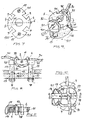
- Figures 1 , 3 and 4 show by way of example the Einknüpfen a rope in the device + ( Figure 1 ): rope node element in the plan with inserted, not yet imposed rope loop; + ( Figure 2): rope node element; cut along AA; BB; + ( Fig. 3):
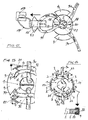
- Rope node element in the plan with inserted and once folded rope loop + ( Figure 4): rope node element in the plan, frictionally tied into a rope; + ( Fig.5 ); Rope node element knotted into a rope with additionally attached rope loop for attaching a load, or for hanging the element on a solid surface; + ( Figure 6 ): rope node element in the plan view with continuous slot axially to a tine + ( Fig. 7,8,9): rope knot element fixed or slidably mounted on a substrate; + ( Fig. 10): node element with a peelable prong in the top view; + ( Fig. 11): Section along DD, Fig. 10 + ( Fig. 12): Node element of Fig.
- disk-shaped component (1) preferably approximately circular or elliptical in plan view ( FIGS . 7, 8 and 9), with a circular hole in the middle (2).
- the sketched axes AA and BB define 4 sectors on the disc (each 90 degrees), axially to each bisector of these sectors, the disc has an incised preferably trapezoidal slot (3).
- a total element thus has a total of 4 slots (3), which results in a total of 4 teeth (4) on the aforementioned axes.
- the diameter of the central hole (2) depends mainly on the largest rope diameter for which the element is still to be used: minimum diameter is twice rope diameter plus a few millimeters for handling, possibly inserted locking pin (6) and ev. Additional suspensions ( Fig . 5 ).
- the slots (3) open inwards in a trapezoidal shape so that the knotted rope (30) holds more reliably on the element. The approximately pointed inner Trapezecken should the cable (30) but only minimal pinch, otherwise the rope (30) is very difficult to solve again from the element.
- the width of the slot (3) on the outside of the disc should at least the maximum rope diameter used plus a few millimeters for easier Matching and unfolding correspond.
- the width of the slot (3) at the trapezium base (5) inside, is about twice the rope thickness, the depth of the slot (3) should at least equal to the rope diameter plus a few millimeters.
- the concrete geometric design of an element must ensure that between tooth (4) and central hole (2) a pad, or support for below described crossing cable sections (32) is present, which means there must be disc material in a flat form.
- the knotting of the node element in the rope (30) is based on FIG . 1,3 u . 4 is formed in the rope (30) at the desired location a loop (31) is formed, this is inserted through the central hole (2) ( Fig . 1 ), then pulled over the tine (4) on one side of the element ( Fig. 3) and finally slipped over the tine (4) on the opposite side and imposed there ( Fig . 4 ), the rope is thus in all 4 slots (3) to lie.
- the cable (30) is tightened by tightening on one of the rope sections above or below the element.
- a securing pin (6) can be inserted laterally through a small bore (7) in the middle by the teeth (4), radially to the node disc, in the form of, for example, a rod-shaped splint (6).
- the holes (7) for this purpose are expediently provided at all points (4).
- This pin (6) has no load-bearing function, or is not necessary for holding the connection knot element - rope, but prevents when moving the node element along the rope that this falls out of the rope, but this is desirable, the pin (6 ) not used or removed before.
- the tying is summarized as an example as follows: Take knot element in his hand, at the desired rope point in this tie, plug in locking pin (6) or not.
- the loosening, or loosening of the node element from the rope (30) takes place from one side of the cable sections, which must be relieved for this purpose.
- the rope (30) is plugged in the direction node element until the occupied loop (31) can come out of the tine ( Figure 3), the loop (31) is picked up with the fingers and out of the two prongs (4) unscrewed.
- the loop (31) can thereby be pulled out of the rope and the Knotanelement, the rope falls off the element, or vice versa, the element of the rope - except it was the locking pin (6) used.
- Fig. 4 shows as the most essential part of the holding action, the two intersecting cable sections (32), which arise due to oa Einknüpfkaes, or design of the element after attachment in the rope (30) on the element.
- a load additionally attached to the node element can be used by way of example as shown in FIG . 5 are shown by another short loop of rope (10) is threaded through the central hole. Via the node element can thus be a load at the desired location, also slidably attached to a rope.
- a node element can also be fixedly suspended from a described cable loop (10) on a substrate and a rope (30) can be fastened to it with the described tying process - FIG . 5 is then to be considered in the reverse direction.
- Fig . Fig. 6 shows a node element whose disc is provided on one side with a slot (26) along a radial serration axis to the central hole (2).
- This slot (26) halves a prong (4), the first during the mooring in the rope (30) to be formed loop (31) can be inserted laterally into the element in this case.
- the outline shape of the disc is excluded to disk thickness from the substrate (12.1), the element inserted into this negative mold (12) and pulled out in the application, with the hole in the center (2) acts as a finger engagement.
- the frictional connection to the substrate (12.1) can be done by two rigidly mounted on the disc bolts (11) which slide into corresponding bushes (13) in the ground (12.1) under the recess (12).
- the only remaining tine (4.1) of a side is releasably connected to the element body (1.1) by having on both sides tabs (16) which engage over the element body (1.1).
- a fastener (17) which is inserted through both tabs (16), a bore (18) in the element body and the central hole (2), the tine (4.1) is secured against unintentional release of the element body.
- the node element is in the assembled state ( Figure 10 ) to handle as the standard node element ( Figure 1) .
- the side (30) can be additionally secured to the node element by partially closing the slots (3) of the element Fig. 13 shows Closure element (21) that slots (3) on the outside can close approximately half - the remaining open gap is thus something less than the rope diameter.
- This closure element may for example be a flat tab (21), fixed in the soffit of the slots (3) as a separate Accessory or fixed to the element body formed, fulfills the function described above: resilient both rotatable inward and outward.
- Fig . 14 shows lying on the outer edge of the wheel manually displaceable sliding bolt (22) with which slots (3) can be completely closed outside: two bars (22) on the disk circumference, slightly shorter than the arc between two slots (3) close either two of the four slots.
- the latch (22) can be pushed to the left or to the right, depending on where the loop to be secured (31).
- the concentric to the disc latch (22) have z.
- B. a C-shaped cross-section and are guided in a groove (24), which is also incorporated concentrically with the disc just inside the circumference in the element body.
- plastic offers, also metal materials are suitable, as well Combinations of said materials (eg inner ring of metal, the rest of plastic). It could also be made of wood or wood-based materials getting produced.
Landscapes
- Health & Medical Sciences (AREA)
- General Health & Medical Sciences (AREA)
- Business, Economics & Management (AREA)
- Emergency Management (AREA)
- Ropes Or Cables (AREA)
- Emergency Lowering Means (AREA)
- Food-Manufacturing Devices (AREA)
- Lift-Guide Devices, And Elevator Ropes And Cables (AREA)
Applications Claiming Priority (2)
| Application Number | Priority Date | Filing Date | Title |
|---|---|---|---|
| AT17382003 | 2003-11-03 | ||
| AT17382003A AT500316B1 (de) | 2003-11-03 | 2003-11-03 | Seilknotenelement |
Publications (2)
| Publication Number | Publication Date |
|---|---|
| EP1527800A2 true EP1527800A2 (fr) | 2005-05-04 |
| EP1527800A3 EP1527800A3 (fr) | 2006-08-02 |
Family
ID=34397365
Family Applications (1)
| Application Number | Title | Priority Date | Filing Date |
|---|---|---|---|
| EP04450197A Withdrawn EP1527800A3 (fr) | 2003-11-03 | 2004-10-29 | Elément de réalisation d'un noeud à une corde. |
Country Status (2)
| Country | Link |
|---|---|
| EP (1) | EP1527800A3 (fr) |
| AT (1) | AT500316B1 (fr) |
Cited By (3)
| Publication number | Priority date | Publication date | Assignee | Title |
|---|---|---|---|---|
| GB2464928A (en) * | 2008-10-28 | 2010-05-05 | Latchways Plc | Safety line capture device |
| CN108301119A (zh) * | 2018-03-19 | 2018-07-20 | 厦门承亿橡塑五金工业有限公司 | 一种绳子的辅助打结器及绳子打结方法 |
| US20220054872A1 (en) * | 2020-08-19 | 2022-02-24 | Cmc Rescue, Inc. | Convertible harness |
Citations (3)
| Publication number | Priority date | Publication date | Assignee | Title |
|---|---|---|---|---|
| CH494041A (de) | 1968-07-19 | 1970-07-31 | Richard Dr Med Hopf | Abseilgerät |
| US4774742A (en) | 1987-04-03 | 1988-10-04 | Lloyd Johnson | Rappelling tool |
| US5307751A (en) | 1992-07-02 | 1994-05-03 | David Shell | Device for releaseably connecting rope ends in tension |
Family Cites Families (1)
| Publication number | Priority date | Publication date | Assignee | Title |
|---|---|---|---|---|
| US4763595A (en) * | 1985-06-28 | 1988-08-16 | Shaffner Lorn O | Line fastening unit |
-
2003
- 2003-11-03 AT AT17382003A patent/AT500316B1/de not_active IP Right Cessation
-
2004
- 2004-10-29 EP EP04450197A patent/EP1527800A3/fr not_active Withdrawn
Patent Citations (3)
| Publication number | Priority date | Publication date | Assignee | Title |
|---|---|---|---|---|
| CH494041A (de) | 1968-07-19 | 1970-07-31 | Richard Dr Med Hopf | Abseilgerät |
| US4774742A (en) | 1987-04-03 | 1988-10-04 | Lloyd Johnson | Rappelling tool |
| US5307751A (en) | 1992-07-02 | 1994-05-03 | David Shell | Device for releaseably connecting rope ends in tension |
Cited By (4)
| Publication number | Priority date | Publication date | Assignee | Title |
|---|---|---|---|---|
| GB2464928A (en) * | 2008-10-28 | 2010-05-05 | Latchways Plc | Safety line capture device |
| CN108301119A (zh) * | 2018-03-19 | 2018-07-20 | 厦门承亿橡塑五金工业有限公司 | 一种绳子的辅助打结器及绳子打结方法 |
| US20220054872A1 (en) * | 2020-08-19 | 2022-02-24 | Cmc Rescue, Inc. | Convertible harness |
| US12558581B2 (en) * | 2020-08-19 | 2026-02-24 | Cmc Rescue, Inc. | Convertible harness |
Also Published As
| Publication number | Publication date |
|---|---|
| EP1527800A3 (fr) | 2006-08-02 |
| AT500316B1 (de) | 2007-03-15 |
| AT500316A1 (de) | 2005-11-15 |
Similar Documents
| Publication | Publication Date | Title |
|---|---|---|
| DE102015107075B3 (de) | Befestigungssystem für eine Sport- und Freizeitvorrichtung | |
| EP3839277B1 (fr) | Dispositif de liaison permettant d'accoupler une charge à un oeillet au moyen d'un boulon porteur | |
| EP0859647B1 (fr) | Appareil de levage et d'abaissement a elingue | |
| EP1229258B1 (fr) | Mousqueton constitué d'un corps muni d'une ouverture d'accès | |
| DE2646024C3 (de) | Lösbares, schellenartiges sowie einstückiges Verbindungsmittel, insbesondere zum Schließen von Tüten oder zum Zusammenbinden eines Pflanzenstiels bzw. -Stammes mit einer Stütze oder auch zum Verbinden einer Vielzahl von elektrischen Kabeln | |
| DE2625651C2 (de) | Schneekette | |
| EP2065077B1 (fr) | Ensemble pour l'installation d'un slackline | |
| AT500316B1 (de) | Seilknotenelement | |
| DE10220758B4 (de) | Aufhängevorrichtung für ein Kletterseil | |
| EP4052931B1 (fr) | Élément d'assemblage destiné à la fixation d'un dispositif antipatinage à une roue de véhicule | |
| DE102016001396B4 (de) | Variabel einsetzbare Zugseilklemme | |
| EP2580490A1 (fr) | Attache d'extrémité de corde | |
| DE3712227A1 (de) | Seilsicherung fuer ein bergsteiger-kletterseil | |
| DE2310584C3 (fr) | ||
| EP2342469A1 (fr) | Mousqueton muni d'une sécurité de suspension | |
| AT392591B (de) | Verbindungsschlinge | |
| EP1159987A2 (fr) | Frein de câble | |
| AT504043A1 (de) | Seilbrems- und befestigungsvorrichtung | |
| DE3632537A1 (de) | Verfahren und vorrichtung zur befestigung eines kletterseils an einem kletterguertel | |
| EP0773714B1 (fr) | Collier pour retenir et guider des animaux | |
| AT392592B (de) | Selbstblockierendes abseilgeraet | |
| DE102006021081A1 (de) | An einer Leine entfernbar anbringbare Vorrichtung und Verfahren zu ihrer Anbringung und Entfernung | |
| EP4169584A1 (fr) | Ceinture de protection personnelle contre les chutes avec un connecteur | |
| DE2518724A1 (de) | Kieferorthopaedisches, elastisches band | |
| DE2413885C3 (de) | Schnürverschluß mit einer Vorrichtung für eine blockierende Bindung der freien Enden des Schnürsenkels |
Legal Events
| Date | Code | Title | Description |
|---|---|---|---|
| PUAI | Public reference made under article 153(3) epc to a published international application that has entered the european phase |
Free format text: ORIGINAL CODE: 0009012 |
|
| AK | Designated contracting states |
Kind code of ref document: A2 Designated state(s): AT BE BG CH CY CZ DE DK EE ES FI FR GB GR HU IE IT LI LU MC NL PL PT RO SE SI SK TR |
|
| AX | Request for extension of the european patent |
Extension state: AL HR LT LV MK |
|
| PUAL | Search report despatched |
Free format text: ORIGINAL CODE: 0009013 |
|
| AK | Designated contracting states |
Kind code of ref document: A3 Designated state(s): AT BE BG CH CY CZ DE DK EE ES FI FR GB GR HU IE IT LI LU MC NL PL PT RO SE SI SK TR |
|
| AX | Request for extension of the european patent |
Extension state: AL HR LT LV MK |
|
| AKX | Designation fees paid | ||
| REG | Reference to a national code |
Ref country code: DE Ref legal event code: 8566 |
|
| STAA | Information on the status of an ep patent application or granted ep patent |
Free format text: STATUS: THE APPLICATION IS DEEMED TO BE WITHDRAWN |
|
| 18D | Application deemed to be withdrawn |
Effective date: 20070402 |