EP1527720A1 - Elektischer Wassererhitzer - Google Patents
Elektischer Wassererhitzer Download PDFInfo
- Publication number
- EP1527720A1 EP1527720A1 EP05002219A EP05002219A EP1527720A1 EP 1527720 A1 EP1527720 A1 EP 1527720A1 EP 05002219 A EP05002219 A EP 05002219A EP 05002219 A EP05002219 A EP 05002219A EP 1527720 A1 EP1527720 A1 EP 1527720A1
- Authority
- EP
- European Patent Office
- Prior art keywords
- filter
- water
- liquid
- vessel
- steam
- Prior art date
- Legal status (The legal status is an assumption and is not a legal conclusion. Google has not performed a legal analysis and makes no representation as to the accuracy of the status listed.)
- Granted
Links
- 238000010438 heat treatment Methods 0.000 title claims abstract description 77
- XLYOFNOQVPJJNP-UHFFFAOYSA-N water Substances O XLYOFNOQVPJJNP-UHFFFAOYSA-N 0.000 title description 106
- 239000007788 liquid Substances 0.000 claims abstract description 64
- 239000000463 material Substances 0.000 claims description 21
- 239000008187 granular material Substances 0.000 claims description 6
- 230000005484 gravity Effects 0.000 claims 1
- 238000009835 boiling Methods 0.000 description 28
- 238000004891 communication Methods 0.000 description 16
- OKTJSMMVPCPJKN-UHFFFAOYSA-N Carbon Chemical compound [C] OKTJSMMVPCPJKN-UHFFFAOYSA-N 0.000 description 15
- 239000012530 fluid Substances 0.000 description 15
- 230000002035 prolonged effect Effects 0.000 description 14
- 230000033001 locomotion Effects 0.000 description 10
- 238000000034 method Methods 0.000 description 9
- 238000001914 filtration Methods 0.000 description 8
- 239000003456 ion exchange resin Substances 0.000 description 8
- 229920003303 ion-exchange polymer Polymers 0.000 description 8
- 230000007246 mechanism Effects 0.000 description 8
- ZAMOUSCENKQFHK-UHFFFAOYSA-N Chlorine atom Chemical compound [Cl] ZAMOUSCENKQFHK-UHFFFAOYSA-N 0.000 description 7
- 229910052799 carbon Inorganic materials 0.000 description 7
- 239000000460 chlorine Substances 0.000 description 7
- 229910052801 chlorine Inorganic materials 0.000 description 7
- 238000010276 construction Methods 0.000 description 6
- 230000008569 process Effects 0.000 description 6
- 239000011347 resin Substances 0.000 description 6
- 229920005989 resin Polymers 0.000 description 6
- 238000007789 sealing Methods 0.000 description 6
- 238000004659 sterilization and disinfection Methods 0.000 description 6
- 239000003651 drinking water Substances 0.000 description 5
- 235000020188 drinking water Nutrition 0.000 description 5
- 230000000694 effects Effects 0.000 description 5
- 239000004033 plastic Substances 0.000 description 5
- 229920003023 plastic Polymers 0.000 description 5
- NWUYHJFMYQTDRP-UHFFFAOYSA-N 1,2-bis(ethenyl)benzene;1-ethenyl-2-ethylbenzene;styrene Chemical compound C=CC1=CC=CC=C1.CCC1=CC=CC=C1C=C.C=CC1=CC=CC=C1C=C NWUYHJFMYQTDRP-UHFFFAOYSA-N 0.000 description 4
- 241000894006 Bacteria Species 0.000 description 4
- 238000009833 condensation Methods 0.000 description 4
- 230000005494 condensation Effects 0.000 description 4
- 230000001627 detrimental effect Effects 0.000 description 4
- 230000036541 health Effects 0.000 description 4
- 244000005700 microbiome Species 0.000 description 4
- 230000000717 retained effect Effects 0.000 description 4
- OYPRJOBELJOOCE-UHFFFAOYSA-N Calcium Chemical compound [Ca] OYPRJOBELJOOCE-UHFFFAOYSA-N 0.000 description 3
- FYYHWMGAXLPEAU-UHFFFAOYSA-N Magnesium Chemical compound [Mg] FYYHWMGAXLPEAU-UHFFFAOYSA-N 0.000 description 3
- 230000004888 barrier function Effects 0.000 description 3
- 230000008901 benefit Effects 0.000 description 3
- 239000011575 calcium Substances 0.000 description 3
- 229910052791 calcium Inorganic materials 0.000 description 3
- 238000005660 chlorination reaction Methods 0.000 description 3
- 238000005056 compaction Methods 0.000 description 3
- 230000000295 complement effect Effects 0.000 description 3
- 239000000356 contaminant Substances 0.000 description 3
- 238000000151 deposition Methods 0.000 description 3
- 150000002500 ions Chemical class 0.000 description 3
- -1 landfills Substances 0.000 description 3
- 239000011777 magnesium Substances 0.000 description 3
- 229910052749 magnesium Inorganic materials 0.000 description 3
- 230000009467 reduction Effects 0.000 description 3
- RYGMFSIKBFXOCR-UHFFFAOYSA-N Copper Chemical compound [Cu] RYGMFSIKBFXOCR-UHFFFAOYSA-N 0.000 description 2
- XEEYBQQBJWHFJM-UHFFFAOYSA-N Iron Chemical compound [Fe] XEEYBQQBJWHFJM-UHFFFAOYSA-N 0.000 description 2
- HCHKCACWOHOZIP-UHFFFAOYSA-N Zinc Chemical compound [Zn] HCHKCACWOHOZIP-UHFFFAOYSA-N 0.000 description 2
- 229910052793 cadmium Inorganic materials 0.000 description 2
- BDOSMKKIYDKNTQ-UHFFFAOYSA-N cadmium atom Chemical compound [Cd] BDOSMKKIYDKNTQ-UHFFFAOYSA-N 0.000 description 2
- 229910052802 copper Inorganic materials 0.000 description 2
- 239000010949 copper Substances 0.000 description 2
- 230000001419 dependent effect Effects 0.000 description 2
- 230000008021 deposition Effects 0.000 description 2
- 238000011049 filling Methods 0.000 description 2
- 239000008233 hard water Substances 0.000 description 2
- 239000008236 heating water Substances 0.000 description 2
- 238000011068 loading method Methods 0.000 description 2
- 230000000813 microbial effect Effects 0.000 description 2
- 230000002906 microbiologic effect Effects 0.000 description 2
- 238000013021 overheating Methods 0.000 description 2
- 230000002093 peripheral effect Effects 0.000 description 2
- 239000000575 pesticide Substances 0.000 description 2
- 238000005096 rolling process Methods 0.000 description 2
- 241000894007 species Species 0.000 description 2
- 238000003860 storage Methods 0.000 description 2
- 239000011800 void material Substances 0.000 description 2
- 229910052725 zinc Inorganic materials 0.000 description 2
- 239000011701 zinc Substances 0.000 description 2
- 229910002651 NO3 Inorganic materials 0.000 description 1
- NHNBFGGVMKEFGY-UHFFFAOYSA-N Nitrate Chemical compound [O-][N+]([O-])=O NHNBFGGVMKEFGY-UHFFFAOYSA-N 0.000 description 1
- 239000004743 Polypropylene Substances 0.000 description 1
- 241001505400 Strix Species 0.000 description 1
- 230000002411 adverse Effects 0.000 description 1
- 239000003905 agrochemical Substances 0.000 description 1
- 239000004411 aluminium Substances 0.000 description 1
- XAGFODPZIPBFFR-UHFFFAOYSA-N aluminium Chemical compound [Al] XAGFODPZIPBFFR-UHFFFAOYSA-N 0.000 description 1
- 229910052782 aluminium Inorganic materials 0.000 description 1
- 239000010828 animal waste Substances 0.000 description 1
- 239000010425 asbestos Substances 0.000 description 1
- 235000013361 beverage Nutrition 0.000 description 1
- 230000000903 blocking effect Effects 0.000 description 1
- 239000000969 carrier Substances 0.000 description 1
- 150000001793 charged compounds Chemical class 0.000 description 1
- 230000008878 coupling Effects 0.000 description 1
- 238000010168 coupling process Methods 0.000 description 1
- 238000005859 coupling reaction Methods 0.000 description 1
- 230000002939 deleterious effect Effects 0.000 description 1
- 230000000881 depressing effect Effects 0.000 description 1
- 230000000994 depressogenic effect Effects 0.000 description 1
- 238000013461 design Methods 0.000 description 1
- 238000011161 development Methods 0.000 description 1
- 230000018109 developmental process Effects 0.000 description 1
- 238000010586 diagram Methods 0.000 description 1
- 238000004821 distillation Methods 0.000 description 1
- 239000010791 domestic waste Substances 0.000 description 1
- 239000003814 drug Substances 0.000 description 1
- 230000009977 dual effect Effects 0.000 description 1
- 238000005516 engineering process Methods 0.000 description 1
- 239000000835 fiber Substances 0.000 description 1
- 238000005243 fluidization Methods 0.000 description 1
- 238000011010 flushing procedure Methods 0.000 description 1
- 239000000446 fuel Substances 0.000 description 1
- 231100001261 hazardous Toxicity 0.000 description 1
- 230000008821 health effect Effects 0.000 description 1
- 239000012770 industrial material Substances 0.000 description 1
- 229910010272 inorganic material Inorganic materials 0.000 description 1
- 239000011147 inorganic material Substances 0.000 description 1
- 229910052742 iron Inorganic materials 0.000 description 1
- 238000004900 laundering Methods 0.000 description 1
- 238000002386 leaching Methods 0.000 description 1
- 239000011133 lead Substances 0.000 description 1
- QSHDDOUJBYECFT-UHFFFAOYSA-N mercury Chemical compound [Hg] QSHDDOUJBYECFT-UHFFFAOYSA-N 0.000 description 1
- 229910052753 mercury Inorganic materials 0.000 description 1
- VNWKTOKETHGBQD-UHFFFAOYSA-N methane Chemical class C VNWKTOKETHGBQD-UHFFFAOYSA-N 0.000 description 1
- 238000012986 modification Methods 0.000 description 1
- 230000004048 modification Effects 0.000 description 1
- 239000002991 molded plastic Substances 0.000 description 1
- 150000002823 nitrates Chemical class 0.000 description 1
- 230000006911 nucleation Effects 0.000 description 1
- 238000010899 nucleation Methods 0.000 description 1
- 150000002894 organic compounds Chemical class 0.000 description 1
- 238000006385 ozonation reaction Methods 0.000 description 1
- 239000002245 particle Substances 0.000 description 1
- 244000052769 pathogen Species 0.000 description 1
- 238000009428 plumbing Methods 0.000 description 1
- 229920001155 polypropylene Polymers 0.000 description 1
- 238000012545 processing Methods 0.000 description 1
- 230000035755 proliferation Effects 0.000 description 1
- 238000000746 purification Methods 0.000 description 1
- 229910052704 radon Inorganic materials 0.000 description 1
- SYUHGPGVQRZVTB-UHFFFAOYSA-N radon atom Chemical compound [Rn] SYUHGPGVQRZVTB-UHFFFAOYSA-N 0.000 description 1
- 230000008929 regeneration Effects 0.000 description 1
- 238000011069 regeneration method Methods 0.000 description 1
- 239000012260 resinous material Substances 0.000 description 1
- 238000001223 reverse osmosis Methods 0.000 description 1
- 229910052895 riebeckite Inorganic materials 0.000 description 1
- 230000001954 sterilising effect Effects 0.000 description 1
- 229940013840 strix Drugs 0.000 description 1
- 150000003467 sulfuric acid derivatives Chemical class 0.000 description 1
- 238000013022 venting Methods 0.000 description 1
- 239000012855 volatile organic compound Substances 0.000 description 1
- 238000005406 washing Methods 0.000 description 1
Images


Classifications
-
- A—HUMAN NECESSITIES
- A47—FURNITURE; DOMESTIC ARTICLES OR APPLIANCES; COFFEE MILLS; SPICE MILLS; SUCTION CLEANERS IN GENERAL
- A47J—KITCHEN EQUIPMENT; COFFEE MILLS; SPICE MILLS; APPARATUS FOR MAKING BEVERAGES
- A47J27/00—Cooking-vessels
- A47J27/21—Water-boiling vessels, e.g. kettles
- A47J27/21008—Water-boiling vessels, e.g. kettles electrically heated
- A47J27/21058—Control devices to avoid overheating, i.e. "dry" boiling, or to detect boiling of the water
- A47J27/21083—Control devices to avoid overheating, i.e. "dry" boiling, or to detect boiling of the water with variable operating parameters, e.g. temperature or boiling period
-
- A—HUMAN NECESSITIES
- A47—FURNITURE; DOMESTIC ARTICLES OR APPLIANCES; COFFEE MILLS; SPICE MILLS; SUCTION CLEANERS IN GENERAL
- A47J—KITCHEN EQUIPMENT; COFFEE MILLS; SPICE MILLS; APPARATUS FOR MAKING BEVERAGES
- A47J27/00—Cooking-vessels
- A47J27/21—Water-boiling vessels, e.g. kettles
- A47J27/21008—Water-boiling vessels, e.g. kettles electrically heated
- A47J27/21058—Control devices to avoid overheating, i.e. "dry" boiling, or to detect boiling of the water
- A47J27/21066—Details concerning the mounting thereof in or on the water boiling vessel
- A47J27/21075—Details concerning the mounting thereof in or on the water boiling vessel relating to the boiling sensor or to the channels conducting the steam thereto
-
- A—HUMAN NECESSITIES
- A47—FURNITURE; DOMESTIC ARTICLES OR APPLIANCES; COFFEE MILLS; SPICE MILLS; SUCTION CLEANERS IN GENERAL
- A47J—KITCHEN EQUIPMENT; COFFEE MILLS; SPICE MILLS; APPARATUS FOR MAKING BEVERAGES
- A47J27/00—Cooking-vessels
- A47J27/21—Water-boiling vessels, e.g. kettles
- A47J27/21166—Constructional details or accessories
- A47J27/21175—Covers
-
- A—HUMAN NECESSITIES
- A47—FURNITURE; DOMESTIC ARTICLES OR APPLIANCES; COFFEE MILLS; SPICE MILLS; SUCTION CLEANERS IN GENERAL
- A47J—KITCHEN EQUIPMENT; COFFEE MILLS; SPICE MILLS; APPARATUS FOR MAKING BEVERAGES
- A47J27/00—Cooking-vessels
- A47J27/21—Water-boiling vessels, e.g. kettles
- A47J27/21166—Constructional details or accessories
- A47J27/21183—Water filters
-
- C—CHEMISTRY; METALLURGY
- C02—TREATMENT OF WATER, WASTE WATER, SEWAGE, OR SLUDGE
- C02F—TREATMENT OF WATER, WASTE WATER, SEWAGE, OR SLUDGE
- C02F1/00—Treatment of water, waste water, or sewage
- C02F1/001—Processes for the treatment of water whereby the filtration technique is of importance
- C02F1/003—Processes for the treatment of water whereby the filtration technique is of importance using household-type filters for producing potable water, e.g. pitchers, bottles, faucet mounted devices
-
- C—CHEMISTRY; METALLURGY
- C02—TREATMENT OF WATER, WASTE WATER, SEWAGE, OR SLUDGE
- C02F—TREATMENT OF WATER, WASTE WATER, SEWAGE, OR SLUDGE
- C02F1/00—Treatment of water, waste water, or sewage
- C02F1/02—Treatment of water, waste water, or sewage by heating
-
- C—CHEMISTRY; METALLURGY
- C02—TREATMENT OF WATER, WASTE WATER, SEWAGE, OR SLUDGE
- C02F—TREATMENT OF WATER, WASTE WATER, SEWAGE, OR SLUDGE
- C02F1/00—Treatment of water, waste water, or sewage
- C02F1/28—Treatment of water, waste water, or sewage by sorption
- C02F1/283—Treatment of water, waste water, or sewage by sorption using coal, charred products, or inorganic mixtures containing them
-
- C—CHEMISTRY; METALLURGY
- C02—TREATMENT OF WATER, WASTE WATER, SEWAGE, OR SLUDGE
- C02F—TREATMENT OF WATER, WASTE WATER, SEWAGE, OR SLUDGE
- C02F1/00—Treatment of water, waste water, or sewage
- C02F1/42—Treatment of water, waste water, or sewage by ion-exchange
-
- C—CHEMISTRY; METALLURGY
- C02—TREATMENT OF WATER, WASTE WATER, SEWAGE, OR SLUDGE
- C02F—TREATMENT OF WATER, WASTE WATER, SEWAGE, OR SLUDGE
- C02F2201/00—Apparatus for treatment of water, waste water or sewage
- C02F2201/002—Construction details of the apparatus
- C02F2201/006—Cartridges
-
- C—CHEMISTRY; METALLURGY
- C02—TREATMENT OF WATER, WASTE WATER, SEWAGE, OR SLUDGE
- C02F—TREATMENT OF WATER, WASTE WATER, SEWAGE, OR SLUDGE
- C02F2209/00—Controlling or monitoring parameters in water treatment
- C02F2209/02—Temperature
-
- C—CHEMISTRY; METALLURGY
- C02—TREATMENT OF WATER, WASTE WATER, SEWAGE, OR SLUDGE
- C02F—TREATMENT OF WATER, WASTE WATER, SEWAGE, OR SLUDGE
- C02F2209/00—Controlling or monitoring parameters in water treatment
- C02F2209/42—Liquid level
-
- C—CHEMISTRY; METALLURGY
- C02—TREATMENT OF WATER, WASTE WATER, SEWAGE, OR SLUDGE
- C02F—TREATMENT OF WATER, WASTE WATER, SEWAGE, OR SLUDGE
- C02F2303/00—Specific treatment goals
- C02F2303/04—Disinfection
-
- C—CHEMISTRY; METALLURGY
- C02—TREATMENT OF WATER, WASTE WATER, SEWAGE, OR SLUDGE
- C02F—TREATMENT OF WATER, WASTE WATER, SEWAGE, OR SLUDGE
- C02F2307/00—Location of water treatment or water treatment device
- C02F2307/04—Location of water treatment or water treatment device as part of a pitcher or jug
Definitions
- This invention relates to electrically powered appliances for heating water, such as electric kettles, hot water jugs, beverage makers and so on, and in particular to the purification of water in such appliances.
- Drinking water supplies may potentially be contaminated by many sources which may include, but are not limited to, hazardous household wastes, agricultural chemicals, landfills, fuel sources and storage tanks, animal waste, septic systems, industrial materials, incorrect water storage and processing and leaching of materials from plumbing systems.
- Examples of materials which have been identified in drinking water systems include volatile organic compounds, pesticides, pharmaceuticals, radon, lead, mercury, iron, asbestos fibres, nitrates, sulphates, micro-organisms and hardness resulting from excess calcium or magnesium.
- Home treatment systems presently available include carbon filters, ion exchange resins, fibre filters, reverse osmosis, distillation, ozonation, UV treatment and disinfection processes.
- carbon filter will remove most of the organic compounds which can cause taste and odour problems, along with chlorine resulting from disinfection processes which has been implicated as a source of secondary disinfection products that are detrimental to human health.
- the effectiveness of the carbon filter is dependent on the amount of carbon present and the contact time between the carbon and the water.
- carbon filters must be replaced on a regular basis when taste or odour problems reappear, and they also suffer from a capacity to allow the proliferation of bacteria within the filter, which may result in an increased microbiological loading of the resultant filtered water.
- Ion exchange resins work by exchanging ions in the water for those present on the resin, resulting in the removal or reduction in contaminants ions or charged compounds and their replacement by alternate ions from the resin. This allows the reduction or removal of a range of inorganic materials including cadmium, lead, copper, zinc, calcium, magnesium, nitrate and alkalinity. A large number of these species are associated with known health risks and the presence of calcium, magnesium and alkalinity are the cause of hard water. Hard water has a detrimental effect on washing and laundering and other water processes and forms scum on top of heated water e.g. in a teacup. It is particularly undesirable because of the deposition of scale on heating surfaces in domestic appliances, which increases the cost associated with heating water and reduces the lifetime of the appliance.
- the control of micro-organisms in domestic drinking water systems is typically provided by continuous chlorination systems that feed sufficient amounts of chlorine into the water to kill bacteria. Some chlorine must remain in the water in order to ensure the disinfection process is complete. The necessary rate of chlorination is dependent on a number of factors including the rate of flow and the pH of the water system and must therefore be carefully controlled in order to ensure successful application.
- the use of chlorine in water treatment may result in secondary chlorinated organic products that have been shown to result in detrimental health effects. In addition the chlorine residual contributes to taste problems.
- chlorination procedures at a water treatment plant does not necessarily ensure that properly disinfected water is obtained from the supply by the end user as improper application, breaches in the water supply, excess microbiological loading or stagnant or low flow areas in the supply may result in the establishment of bacteria prior to the point of usage.
- the present invention provides a water boiling appliance comprising a filter for treating water being heated in the appliance and a boiling control arranged so as to produce a prolonged boil in the appliance.
- a water boiling appliance is provided not only with a water treatment means, but also with a control which produces a prolonged boil in the appliance.
- a prolonged boil is meant a boil which is prolonged with respect to traditional vessels in which boiling is discontinued after about typically of the order of 5-30 seconds. By prolonging the boil, pathogens potentially present in drinking water are killed. Furthermore, the prolonged boiling period exposes the treatment material to sterilizing steam for a prolonged period, thereby reducing dramatically the risk of microbial growth in the treatment material.
- a further advantage of an extended boiling time is that the continued nucleation of scale particles is allowed to continue throughout this period, thereby depositing the scale in the heating chamber of the appliance. This reduces the amount of scum on the water surface after the water is poured from the appliance.
- the control is configured and arranged so that the water is boiled for at least one minute. This time is in compliance with the World Health Organisation (WHO) recommendation that water should be boiled for at least one minute to kill harmful micro-organisms and bacteria in the water.
- WHO World Health Organization
- the treatment material in the filter comprises both activated carbon and ion exchange resin.
- the treatment material is contained in a cartridge, most preferably an elongate, tubular, cartridge whereby water being poured into the appliance must flow along the length of the cartridge before entering the chamber.
- the performance of the filter is related to the amount of time which the liquid to be filtered spends passing through the filter. Accordingly, for consistent liquid quality, the filtration time should also be consistent.
- the invention provides a liquid treatment filter comprising a filter chamber, a liquid treatment medium within said chamber, said chamber having a restricted outlet so as to control the flow of liquid through the treatment medium.
- the invention provides a method of controlling the treatment of liquid through a liquid treatment medium in a filter treatment chamber comprising providing the chamber with a restricted outlet.
- the outlet restriction helps avoid compaction of the filter material. Furthermore, the restriction allows a reduction in the depth of the filter material bed without adversely affecting performance, which is advantageous from a design part of view.
- the liquid treatment time and thus the quality of the liquid can be controlled by the size of the chamber outlet.
- the outlet of the filter chamber will be less than 1 cm, more preferably less than 6 mm and most preferably around 4 mm. This latter size has been found to give a consistent filter time of about 100 seconds per litre throughout the effective life of the filter, which is satisfactory from the water treatment point of view, and also is not so long that filtered liquid in the heating chamber of the appliance will have boiled before filtration is complete.
- the filter comprises a plastics housing with a mesh provided at its upper and lower ends to retain the filter medium.
- a drainage space is preferably provided below the lower filter leading to the filter outlet. Preferably the space tapers towards the outlet.
- the filter meshes may be, e.g. of plastics and mounted, e.g. bonded to, mounting flanges on the filter body.
- the mesh is supported by, e.g. insert moulded in a support member, e.g. of plastics.
- the filter may be mounted in or to the lid of the liquid heating vessel of the appliance, or in some other location. In some embodiments, therefore, it may depend from an undersurface of the vessel lid. In other embodiments, however, it may be mounted in an upper region of the vessel proper, for example in an opening formed in a wall extending across an upper part of the vessel body.
- the filter comprises means to mount it in its desired location.
- the filter is preferably mounted in any manner that it can be readily removed and replaced. Accordingly the filter may be fitted with a releasable fastener such as a twist lock, bayonet or similar fitting.
- a compartment within the water heating vessel of the appliance into which water to be boiled is poured and from which it leaves via the filter.
- a separate water hopper is provided into which water is filled and which is then mounted on the vessel. This has the advantage that the potentially smaller reservoir, rather than the whole appliance, can be taken to a tap for filling purposes.
- a valve mechanism is preferably incorporated in the water reservoir such that the release of the water is initiated by the positioning of the hopper on the vessel.
- a water heating appliance comprising a heating vessel, a reservoir detachably mountable on said vessel for receiving water to be heated from a water source, filter means for treating water to be heated and valve means operable to release water from the reservoir into the heating vessel when the hopper is positioned on the heating vessel.
- a dual fill gauge showing both the volume in the vessel and an inverse scale indicating the maximum volume to be placed in the hopper may be provided on the chamber.
- Means are preferably provided for retaining a desired volume of water in the heating vessel after pouring so as to ensure that excessive element temperatures are not generated during the initial phase of the heating process by the absence of water on the surface of the heater prior to water being passed through the filter.
- a barrier is provided, for example either on the jug body or the spout filter, in order that a small volume of water is retained in the heated region after the vessel is. emptied using a typical pouring process. This retained volume may be of the order of 100 cm 3 .
- the filter may be mounted in the hopper and a filtered water chamber formed in the hopper such that when the hopper is positioned on the heating vessel a volume of filtered water is immediately released into the heating vessel.
- a filter mesh is preferably provided in the spout of the heating vessel to prevent any scale formed during the heating process from being poured out of the vessel.
- the compaction of the treatment material in the filter, and also the sterilisation of the treatment material may be improved by restricting the venting of the steam to atmosphere. This promotes the flushing of steam through the treatment material.
- the pouring spout of the vessel is provided with a closure which reduces the egress of steam from the spout.
- the closure could, for example, comprise a flap mounted in the spout. Most preferably, the flap would be pivotally mounted so as to be pivoted out of position when water is poured from the vessel.
- the invention provides a water boiling appliance comprising a filter for treating water being poured into the appliance, and a pouring spout through which water is poured from the appliance, said pouring spout being provided with means to reduce or prevent egress of steam therefrom whereby more steam may pass through said filter.
- suitable means may be provided on the hopper which close the spout when in position during heating but which will allow water to be poured from the spout when the hopper is removed.
- the time necessary to treat one litre of water does not exceed one hundred and eighty seconds, this being the amount of time considered necessary to heat the water from room temperature to boiling using a typical high power heating element.
- the heater used in the appliance may be of the traditional sheathed type, either extending into the heating vessel through a wall thereof or, more preferably, mounted on the underside of the base of the vessel.
- the heater is a so-called thick film heater.
- Such heaters are now widely used in kettles and hot water jugs.
- the boiling control for producing a prolonged boiling time may be configured in a number of different ways.
- a standard boiling control such as a Strix U18, U28 or R48 control
- an extended steam path to the actuator of the control Another possibility would be to use a separate timer mechanism initiated by a steam blade or other mechanism which operates to continue boiling for the desired period of time.
- Electronic controls could also be used.
- control is configured and arranged such that the water in the heating vessel is heated at relatively high power until it boils whereafter the power is reduced to maintain a rolling boil for the predetermined desired boiling time.
- This is advantageous in that the total amount of steam generated is reduced, avoiding possible problems of excess condensation outside the appliance, while at the same time producing sufficient steam to flush the filter.
- This control may be achieved electronically or electromechanically, for example by a system as described in WO 99/02080.
- two separate boiling sensitive controls are used.
- the first is in good fluid communication with the chamber such that it operates quite quickly after the water boils. This operates to reduce the heating power, for example by disconnecting one of two or more parallel heating elements.
- the other steam sensitive control is in less good fluid communication with the chamber so that it will not operate for some predetermined time thereafter. When this operates, it can completely disconnect the power supply to the heater, or it may just leave a much smaller "keep warm" element energised.
- the invention provides a liquid heating appliance having a liquid heating vessel provided with relatively high power heating means and relatively low power heating means, a first steam sensitive control for controlling the high power heating means and a second steam sensitive control for controlling the low power heating means.
- the steam path to the second steam sensitive control may be via a steam passage such as a steam pipe which is in fluid communication with the interior of the vessel, and to delay the actuation of the second control, a constriction may be formed in the steam passage, most preferably at the entrance to the passage.
- the constriction should preferably have a minimum dimension of more than about 1mm.
- the constriction may be in the form of an aperture in a closure of the passage, and preferably it comprises a slot formed in the end of the passage.
- the closure is angled to the horizontal, most preferably by at least 30°.
- the invention provides a steam passage in or for a liquid boiling appliance, said passage having a constriction to limit the flow of steam into or through the passage.
- the invention provides a liquid heating appliance having first and second steam sensitive controls arranged in fluid communication with the interior of a liquid heating vessel of the appliance and comprising means for interrupting or restricting the fluid communication between the first control and the interior of the liquid heating vessel upon operation of the first control.
- the interruption or restriction of the fluid communication with the vessel interior may be effected by a shutter which selectively covers or uncovers an aperture through which the steam flows to the first control and which is operatively coupled to the first control.
- the shutter may be mounted for linear or, more preferably, pivotal movement.
- the fluid communication between the second control and the interior of the vessel is interrupted or restricted until the first control has operated. This will allow the full amount or a greater amount of steam to act on the first control, thereby ensuring rapid operation thereof.
- the invention provides a liquid heating appliance comprising first and second steam sensitive controls each arranged in fluid communication with the interior of a liquid heating vessel of the appliance and comprising means for interrupting or restricting the fluid communication between the second control and the interior of the liquid heating vessel until operation of the first control.
- this interruption or restriction is effected by the flow interruption or restriction means of the first control.
- a single flow interruption or restriction means may be provided which alternately interrupts or restricts the flow of steam to one or other of the controls.
- a linearly or preferably rotationally reciprocating shutter is operatively coupled to the first control to effect selective interruption of the steam supply to the first and second controls.
- a common actuator such as a control knob or the like.
- the actuator should be such that operation of the first control causes some degree of movement of the actuator, to indicate that the control has operated, and operation of the second control then producing a further movement of the actuator means. Resetting the actuator should then reset both controls.
- a common actuator is provided for both controls.
- the actuator incorporates a lost motion mechanism to ensure that operation of the first control does not cause the actuator means to move so far as to operate the second control.
- the actuator may, for example, comprise a linearly movable arm extending between the two controls.
- the actuator is a split actuator comprising associated actuator parts, a first actuator part operatively coupled to the first control and a second actuator part operatively coupled to the second control.
- the actuator parts are preferably arranged such that should the first control operate then only the first actuator part will move but should the second control operates then at least the second actuator part will move.
- the arrangement is preferably such that should the second control operate before the first, then both actuator parts will move together and the first control also be operated by the first actuator part.
- the second control incorporates overheat protection means or means which operate the second control when the appliance is lifted from a support surface such that both the high power and low power heating means are switched off.
- the arrangement may have application outside the particular arrangement described above where two boiling controls are employed, for example in any arrangement wherein an appliance has high power and low power heating means which can be selectively energised, for example where the second heater is a keep warm or simmer heater intended to keep liquid in the appliance warm, but not necessarily boiling, after it has boiled initially.
- the invention provides a liquid heating appliance comprising first and second heating means and first and second controls for controlling said heating means, and an actuator for actuating said controls, said actuator comprising first and second associated parts respectively operatively coupled to the first and second controls and arranged so as to permit operation of the first control to switch out said first heating means without switching out said second heating means and so as to ensure switching out of both heaters upon operation of the second control to switch out the second heater.
- the invention also provides a liquid heating appliance comprising first and second heating means and first and second controls for controlling said heating means, and an actuator for actuating said controls, said actuator comprising first and second associated parts respectively operatively coupled to the first and second controls and movable between respective on and off positions, the parts being arranged so as to permit movement of the first actuator part from its on to its off position without movement of the second part from its on to its off position.
- the actuator parts are pivotally mounted about a common axis.
- the parts are interlocking in profile, and most preferably, a part of one part projects into the other, whereby they may both be easily operated upon together by a user.
- the first actuator part may be arranged to overlie the second part such that when in one position, its movement from that position will be away from the second part and so not cause movement of the second part.
- the second actuator part may, however, be provided with a lip, lug or the like to pick up and move first actuator part if it has not already moved away from the second part.
- the interlocking profiles of the parts may, if necessary, be tapered to produce this effect.
- the invention provides a liquid heating appliance comprising first and second heating means and first and second controls for controlling said heating means, and an actuator for manually actuating said controls, said actuator comprising associated first and second parts respectively operatively coupled to the first and second controls and preferably pivotally mounted about a common axis.
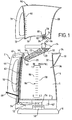
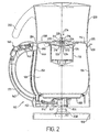
- a water boiling appliance in the form of a cordless electrical kettle 2 comprises a vessel body 4 defining a water boiling vessel 5 and a power base unit 6.
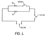
- a thick film heater 8 is arranged in the bottom of the vessel body 4 in a known manner.
- the heater comprises two heating tracks 10, 12 arranged in parallel, as shown schematically in Figure 4.
- the first heater track 10 is rated at about 1800W and the second track 12 at about 400W.
- the kettle further comprises a removable lid 14 and, removably mounted to that lid 14, an elongate filter cartridge 16.
- the cartridge 16 comprises a tubular outer wall 18 of plastics material closed at either end by mesh 20.
- the cartridge contains a combination of activated carbon and ion exchange resin 22.
- the cartridge 16 is, for example, clipped or twist locked into the lid 14.
- the cartridge 16 is mounted so as to slope away from the front of the vessel body 4.
- the lid has an opening 24 above the cartridge 16.
- the vessel body 4 is provided with a pouring spout 30 at its upper end.
- a removable filter mesh 32 is provided in the spout to prevent scale and the like from being poured from the vessel body.
- a pivotally mounted flap 34 is arranged in the mouth of the spout for reasons to be explained further below.
- a barrier 36 is provided on the vessel body 4 just below the spout 30 for reasons which will also be explained further below.
- the appliance 2 is provided with a control which comprises two thermally sensitive switch units 40, 42.
- the first switch 40 is a steam sensitive switch unit arranged in the upper part of the handle 44 of the appliance 2.
- This switch 40 can for simplicity be a standard steam switch such as the Applicant's own R48 switch.
- This switch 40 is in good fluid communication with the interior of the vessel 5 via a steam opening 46 provided in the upper part of the vessel body 4.
- the switch 40 is, as shown in Figure 4, arranged in circuit with one of the tracks 10 of the heater 8.
- the second switch unit 42 is arranged under the bottom of the vessel body 4. Again this switch 42 is a steam sensitive switch which is in fluid communication with the interior of the vessel 5 via a second opening 48 in the upper part of the vessel body 4 and a steam pipe 50.
- the opening 48 and/or steam pipe 50 are arranged and configured such that the switch unit 42 is in much more remote fluid communication with the space 5 than the first switch unit 40.
- the switch unit 42 also comprises overheat protection means for the heater 8.
- the switch unit 42 is one of the Applicant's U28 series of controls comprising a steam sensitive bimetallic actuator 52 which upon operation trips a lever arm 54 which opens a set of contacts (not shown) in the control unit 42.
- a pair of bimetallic actuators (not shown) which are arranged in good thermal contact with the heater 8 act to open the same contacts in the event of the appliance overheating.
- the switch unit 42 is arranged in series with both heater tracks 10, 12.
- the control unit 42 also incorporates a cordless electrical connector 56 for engagement with a complementary connector 58 on the base unit 6.
- a control knob 60 mounted on a rod 62 which extends between the first and second switch units. At its lower end, the rod is directly coupled to the lever arm 54 of the control unit 42 such that when the knob is moved to an "on” position, the lever arm 54 is also moved in a direction to reset the switch unit 42. If the knob 60 is moved to an "off” position, it will also move the lever arm 54 to its “off” position. Similarly should the switch unit 42 operate, the rod 62 and knob 60 are moved to their "off” position.
- the rod 62 is coupled to the switch unit 40 in such a manner that when the control knob is moved to an "on” position it will reset the switch 40. However a degree of lost motion is built into this coupling such that when the switch unit 40 operates it does not move the rod 62.
- a removably mounted water reservoir or hopper 70 This receives water to be poured into the vessel 5 via the filter cartridge 16.
- the hopper 70 is provided with a handle 71 for ease of use.
- the hopper 70 rests with its peripheral rim 72 on the top of the vessel body 4 and it may be provided with appropriate locating means for accurately positioning the reservoir 70 on the vessel body 4.
- An opening 74 is provided in the base 76 of the hopper 70 which aligns with the opening 24 in the lid 14.
- the opening is fitted with a valve 78 comprising a rubber sealing member 80, a shaft 82 attached to the sealing member 80 and having a head 84.
- a spring 86 is arranged between the base 76 of the hopper 70 and the head and acts normally to bias the sealing member 80 against its seat to close the opening.
- the head 84 is pushed upwardly to release the valve and allow water to flow into the vessel 5.
- a filter life indicator "clock" 90 or the like may be provided on the hopper 70.
- the hopper 70 may be filled with a gauge 92 showing the amount of liquid in the hopper. This is useful if a specified amount of water is to be introduced into the vessel 5 for boiling. In order that the vessel 5 is not overfilled with water, it too may be provided with a gauge 94. This shows on one side 96 how much liquid is in the vessel 2 and on the other side 98 how much liquid would have to be added to the hopper to fill the vessel to its maximum filling level.
- a desired amount of water is introduced into the hopper 70 which is placed then on the top of the vessel body 4.
- the valve shaft 82 is pushed upwardly when the valve head 84 abuts against the mesh 20 of the filter cartridge 16 to open the valve 80 and allow water to flow through the cartridge 16 into the vessel 5.
- the water passes through the cartridge it is treated by the filter material to remove deleterious contents.
- the kettle 2 is then switched on by the knob 60, which closes both switches 40,42 to energise both heating tracks 10, 12 of the heater so that the water in the kettle is heated with 2200W power. Water may still flow into the kettle 2 while the water is being heated.
- the hopper 70 can then be removed.
- the end of the steam pipe 50 is offset with respect to the bimetallic actuator 52 so that the latter is not heated very quickly by condensation of steam thereon.
- the steam pipe 50 may be constricted to limit the flow of steam to the actuator 52.
- the knob 60 can be moved to re-close the switches 40, 42 to re-energise the heater 8, and more liquid added to the vessel 5 from the hopper 70 through the filter 16.
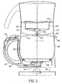
- a cordless electrical kettle 102 comprises a vessel body 104 defining a water heating vessel 105 and a power base unit 106.
- a thick film heater 108 is arranged in the bottom of the vessel body 104.
- the heater comprises two heating tracks 10, 12 as shown schematically in Figure 4.
- the kettle comprises a lid 114 and, removably mounted thereto, a cylindrical filter cartridge 116.
- the construction of the cartridge 116 and its attachment to the lid is described in greater detail below with reference to Figs. 8 and 9.
- the cartridge 116 contains a combination of activated carbon and ion exchange resin.
- the lid has an opening 124 above the cartridge 116.
- the vessel body 104 is provided with a pouring spout 130 at its upper end.
- a removable filter (not shown) may be provided in the spout 130 to prevent scale and the like from being poured from the spout 130.
- the kettle 102 is provided with two steam sensitive switch units 140, 142.
- the first switch unit 140 is one of the Applicant's R48 steam switches which are well known in the art and need not, therefore, be described in detail here.
- This switch unit 140 is in good fluid communication with the vessel 105 via a steam opening 146 provided in the upper part of the vessel body 104.
- the second switch unit 142 is one of the Applicant's U28 controls which is in fluid communication with the vessel 105 via the opening 146 and a steam pipe 150.
- the U28 comprises a steam sensitive bimetal 152, a pair of overheat protection bimetals (not shown) in good thermal contact with the heater 108 as well as an electrical connector 156 for engagement with a complementary connector 158 on the base unit 106.
- the connector 158 is one of the Applicant's P72 connectors.
- a push rod 162 extends between the first and second switch units 140, 142. At its lower end, the push rod is directly coupled to the lever arm 154 of the control unit 142. The upper end of the push rod 162 is coupled to one end of a two-part control knob 160. The other end of the control knob 160 is coupled to the first steam switch 140.
- a cam 161 is provided on the spring loaded movable arm 164 of the control 140 which engages with a lug 166 provided on a first part 168 of the knob 160 which is pivotally mounted about an axis 170.
- the upper end of the push rod 162 is provided with a guide 172 in which is received a pin 174 attached to a second part 176 of the control knob 160 which is also pivotally mounted about the axis 170.
- the push rod 162 passes through the handle 171 of the vessel, but it could, in other embodiments pass along the back wall thereof.
- first and second knob parts 168, 176 are form interlocking, with the first part 168 having a nose 178 which projects into a complementary recess 180 formed in the second part 176.
- first and second parts 168, 176 are separately pivotable about the axis 170.
- a pivotally mounted, generally L-shaped shutter 190 is also coupled to the first switch 140.
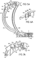
- This shutter 190 is movable between two positions. In the first position shown in Figures 5B and 7B the shutter 190 blocks the entrance 192 to the steam pipe 150, thereby preventing steam reaching the second control 142. In the second position shown eg in Figures 5A and 7A it blocks the steam entrance 194 to the first steam switch 140.
- a water hopper 200 is received on the lid 114 of the vessel 104.
- the hopper 200 is provided with a handle 202 for ease of use.
- the hopper 200 rests with its peripheral rim 204 on the top of the vessel body 104. It will be seen that the front portion 205 of the rim 204 extends down into the pouring spout 130 to perform a similar function to the flap 32 in the first embodiment.
- An opening 206 is provided in the base 208 of the hopper 200 which aligns with the opening 124 in the lid 114.
- the lid opening 124 is provided in a well 210 and the hopper opening 206 in a spigot 212 which locates in the well 210.
- the opening 206 is fitted with a valve 214.
- the valve comprises a valve stem 216 slidably mounted in a bore 218 and whose upper end mounts a sealing member 220.
- a spring 222 is arranged in the bore 218 between the base thereof and the lower end 224 of the valve stem and acts normally to bias the sealing member 220 against its seat to close the opening.
- the stem 216 is pushed upwardly by a spigot 226 formed on the lid to release the sealing member 220 and allow water to flow into the vessel 205.
- the filter cartridge 250 is actually arranged within the hopper 252 rather than in the vessel 104.
- the hopper 252 has a generally horizontal dividing wall 254 provided about half to two-thirds down the hopper 252 and the filter 250 is mounted in this wall 254, for example by a bayonet fitting.
- the construction of the filter 250 is generally similar to that of the embodiment of Figure 2 and need not, therefore be described in detail here.
- the filter is, however, slightly squatter than that of the earlier embodiment.
- the base 256 of the hopper locates on the upper surface of the lid 258 of the vessel body 104 and is provided with a valve mechanism 260 the same as that of the embodiment of Figure 2.
- the lid 258 is moulded with a spigot 262 to release the valve 260.
- the effect of the dividing wall 254 is to create a reservoir 270 of filtered water which will be released into the vessel 205 as soon as the hopper 252 is located on the vessel body 104 so that the heater will be covered immediately and thus be unlikely to overheat if the heater is switched on straight away.
- FIGS 5A, 6A and 7A show the operative condition when both heaters 10, 12 are switched off.
- the water hopper 200, 252 can be filled and returned to the vessel 104.
- the knob parts 168, 176 lie in a first, coplanar, position.
- the heaters can be turned on by depressed the knob 160 in the interlocking region 179 of the knob parts so as to move both knob parts 168, 176 together to a second coplanar position shown in Figure 5B in which both heaters are turned on via the respective controls 140, 142 which are operatively coupled to the respective knob parts 168, 170.
- the push rod 162 pushes down on the lever arm 154 of the control 142 and the lug 166 of the first knob part 168 pushes on the cam 161 of the movable part 164 of the control 140 to close the respective sets of contacts within the switch units.
- the upright limb 196 of the steam shutter 190 moves away from the steam opening 194 to the first control 140 so as to permit steam to enter that switch. Its curved limb 198, however, occludes the opening 192 to the steam pipe 150 so as to prevent steam entering the steam pipe 150 and thus reaching'the control 142. As such when liquid in the vessel boils, substantially all the steam entering the steam inlet 146 will be conducted to the first control 140 which will then operate quickly.
- the first control 140 When liquid in the vessel boils, the first control 140 will operate so as to disconnect the main heater of the vessel. In so doing, the cam 162 of the control 140 will move the lug 166, and thus the first knob part 168, back to its original position, as shown in Figures 7A, 7B and 7C. However, because the two knob parts 168, 176 are independently pivotable, the second knob part 176 remains in its second position, whereby the second control 142 does not operate and the lower power heater 12 will remain energised.
- the knob 160 adopts a "broken back" appearance which indicates to a user of the appliance that the water has been brought to boiling and is now in its prolonged boil mode.
- the steam shutter 190 which is coupled to the first control 140 moves to the position shown in Figure 7C in which the vertical limb 196 moves to close the steam opening 194 to the first control 140 and the curved limb 198 moves away from the opening 192 in the top of the steam tube 150 to allow steam to flow to the second control 142.
- the mechanism described above will also allow the main heater 10 to be reconnected during the prolonged low power heating by depressing the nose 178 of the first knob part 204, which effectively returns the system to the condition shown in Figures 5B, 6B and 7B.
- the mechanism is configured to allow both heaters 10, 12 to be switched out in the event of the second control 142 operating before the first control 140, for example in the event of the vessel boiling dry, being switched on dry or if it is lifted from its power stand.
- the interlocking profile of the knob parts 168, 176 is such that should the control 142 operate in such conditions, its movement will translate to the first knob part 168 via the second part 176 to switch off the first control 140.
- the nose 178 and recess 180 may, if necessary, taper inwardly from their respective upper surfaces, or a lip or the like may be provided on the second knob part 176 such that the second knob part 176 will pick up the first part 168 as it moves.
- the filter cartridge 116 comprises a moulded plastics, e.g. polypropylene body 300, contains a bed of ion exchange resin and activated carbon granules 302.
- the granules 302 are retained in the filter body 300 by upper and lower plastics meshes 304, 306. Although these meshes could be simple meshes suitably bonded to the body 302, in this embodiment they are insert moulded into spoked carriers 308, 310 respectively.
- the top of the upper mesh 304 slopes to promote flow of water towards the centre of the cartridge 116.
- the granules are filled to a level 307 below the upper mesh 304, eg about 5mm below.
- the lower end 312 of the body is provided with a tapering drainage void 314 and a restricted aperture 316.
- the angle of the taper is about 20° in this embodiment.
- a plurality of radially extending ribs 318 act to support the lower mesh 306 above the void 314.
- the mesh may for example br ultrasonically bonded to the ribs 318.
- the filter diameter is about 60-65 mm and the opening diameter about 4 mm.
- the bed of filter material 302 is about 40-50 mm.
- the upper end 320 of the body 300 is provided with a flange 322 to which is eg bonded the upper mesh 304.
- the flange 322 is provided with three equispaced twist locking lugs 324 for engagement with corresponding slots 326 in a mounting ring 328 which is suitably attached to the lid 114 of the vessel 102 eg by fasteners extending through holes 330. This allows the cartridge very easily to be installed and also replaced when its life is finished.
- the effect of the restricted opening 316 in the cartridge base is to control the flow of liquid through the filter so as to obtain a consistent flow time through the filter.
- This Figure shows the length of time to filter 1 litre of water, against the total number of litres drained.
- Lines 400 and 402 illustrate results obtained for commercially available filter which have no restrictions on the flow therethrough. It will be seen that there is a wide variation in the flow time and thus in the quality of treated water. Also, it may mean that in certain circumstances, water in the heating vessel into which the water drains will have boiled before filtration is complete. This is not acceptable.
- Lines 404, 406 and 408, however, show the effect of restricting the outlet of a filter.
- Line 404 represents a 2 mm diameter opening
- lines 406 and 408 represent 4mm openings in a standard depth filter and a shallower filter respectively.
- the 2mm opening gives consistent, but slow, filter times while a 4 mm opening (in either a deeper or shallower filter) gives a very satisfactory time of about 100 seconds/litre.
- These sizes are merely illustrative, and the size of the opening can be chosen to give a suitable balance between the quality of the filtered water and the flow time to ensure filtration is complete before liquid in the vessel boils.
- the top of the steam pipe is shown with a restricted circular opening 192 (which may, for example be integrally formed with the pipe, or a separate piece mounted thereto).
- a restricted circular opening 192 which may, for example be integrally formed with the pipe, or a separate piece mounted thereto.
- the steam pipe 150 could be closed by a sloping face having an opening therein.
- the slope e.g. at least 30°, more preferably about 45° acts to prevent condensation build up on the closure which might impede steam flow into the steam tube.
- the opening is preferably over 1mm wide.
- the filter cartridge may be mounted in a wall extending across the vessel 105.
- the upper part of the vessel 105 then acts as the water hopper.
- the hopper may be pivotally mounted to the top of the vessel body around a pivot axis preferably arranged near the handle.
- heating means may be differently configured to the particular configuration shown.
- the heating means may be sheathed heating elements rather than thick film elements as disclosed.
- the heaters or heater tracks may be configured differently. For example two heaters or heater tracks may be arranged in series, rather than in parallel. In such an arrangement the first steam control is arranged to connect the second heater or heater track in series with the first so as to reduce the overall heating power (as the total resistance will be greater). Such arrangements are clearly intended to fall within the scope of the invention.
- the second control will then act to switch off both elements or merely leave energised a further section for keeping water in the vessel 105 warm after it has boiled.
- the individual track portions have been described in the preferred embodiment as having different resistances and thus heating powers, each could be the same.
- the "prolonged boil” heating means would have half the power of the "bring to boil” heating means if they are connected in first connected in parallel and one then switched out by the first control, or one quarter the power if the first control acts to switch both heaters in series.
- the appliance may have more than two heating means which are controlled by respective control means, so from a further broad aspect, the invention provides a liquid heating appliance having multiple heating means and a first steam sensitive control for controlling a first heating means and a second steam sensitive control for controlling a second heating means.
- respective controls could be used to progressively reduce the power of the heating means.
- the split knob mechanism described above may have broader application than the particular heating vessel shown herein.
- it could be used in any situation where different heating levels are required, eg where a main heater and a keep warm heater are provided and can be used in conjunction with boiling controls other than the steam controls described, for example boiling controls of the type which sense the temperature of a sump of the vessel, as shown in WO 97/04694.
- Certain other aspects of the invention may also be used more generally than in an appliance having a filter
- the cartridge is configured to provide a treatment material depth not less than 75 mm. Most preferably it is circular in cross section, with a typical average diameter of 45mm and a typical total internal volume of 120 cm 3 . These figures are, however, merely exemplary and do not limit the scope of the invention.
Landscapes
- Engineering & Computer Science (AREA)
- Food Science & Technology (AREA)
- Organic Chemistry (AREA)
- Environmental & Geological Engineering (AREA)
- Water Supply & Treatment (AREA)
- Chemical & Material Sciences (AREA)
- Life Sciences & Earth Sciences (AREA)
- Hydrology & Water Resources (AREA)
- Cookers (AREA)
- Water Treatment By Sorption (AREA)
- Resistance Heating (AREA)
- Apparatus For Making Beverages (AREA)
- General Preparation And Processing Of Foods (AREA)
Applications Claiming Priority (7)
| Application Number | Priority Date | Filing Date | Title |
|---|---|---|---|
| GBGB9930504.7A GB9930504D0 (en) | 1999-12-23 | 1999-12-23 | Electric water heating vessels |
| GB9930504 | 1999-12-23 | ||
| GB0008560A GB0008560D0 (en) | 2000-04-07 | 2000-04-07 | Electric water heating vessels |
| GB0008560 | 2000-04-07 | ||
| GB0023481 | 2000-09-25 | ||
| GB0023481A GB0023481D0 (en) | 2000-09-25 | 2000-09-25 | Electric water heating vessels |
| EP00985645A EP1220630B2 (de) | 1999-12-23 | 2000-12-20 | Elektischer wassererhitzer |
Related Parent Applications (1)
| Application Number | Title | Priority Date | Filing Date |
|---|---|---|---|
| EP00985645A Division EP1220630B2 (de) | 1999-12-23 | 2000-12-20 | Elektischer wassererhitzer |
Publications (2)
| Publication Number | Publication Date |
|---|---|
| EP1527720A1 true EP1527720A1 (de) | 2005-05-04 |
| EP1527720B1 EP1527720B1 (de) | 2009-02-25 |
Family
ID=27255656
Family Applications (2)
| Application Number | Title | Priority Date | Filing Date |
|---|---|---|---|
| EP00985645A Expired - Lifetime EP1220630B2 (de) | 1999-12-23 | 2000-12-20 | Elektischer wassererhitzer |
| EP05002219A Expired - Lifetime EP1527720B1 (de) | 1999-12-23 | 2000-12-20 | Elektischer Wassererhitzer |
Family Applications Before (1)
| Application Number | Title | Priority Date | Filing Date |
|---|---|---|---|
| EP00985645A Expired - Lifetime EP1220630B2 (de) | 1999-12-23 | 2000-12-20 | Elektischer wassererhitzer |
Country Status (9)
| Country | Link |
|---|---|
| EP (2) | EP1220630B2 (de) |
| CN (4) | CN1304083C (de) |
| AT (2) | ATE423492T1 (de) |
| AU (1) | AU2204801A (de) |
| DE (3) | DE60030455T3 (de) |
| ES (2) | ES2274815T5 (de) |
| GB (1) | GB2363564B (de) |
| PT (1) | PT1527720E (de) |
| WO (1) | WO2001047399A2 (de) |
Cited By (3)
| Publication number | Priority date | Publication date | Assignee | Title |
|---|---|---|---|---|
| WO2008026989A3 (en) * | 2006-07-20 | 2009-03-12 | Purity Ab | Device for purification of a liquid |
| EP1915930A3 (de) * | 2006-10-19 | 2009-10-07 | WIK Far East Ltd. | Wasserkocheinrichtung sowie Filtervorrichtung dafür |
| CN109907642A (zh) * | 2017-12-12 | 2019-06-21 | 佛山市顺德区美的电热电器制造有限公司 | 烹饪器具的上盖加热控制方法及装置 |
Families Citing this family (44)
| Publication number | Priority date | Publication date | Assignee | Title |
|---|---|---|---|---|
| GB2377751B (en) * | 2001-07-20 | 2003-10-15 | Kwei Tang Chang | Electric thermos bottle capable of filtering flowing water |
| GB0204493D0 (en) * | 2002-02-26 | 2002-04-10 | Strix Ltd | Electric liquid heating appliances |
| US6715406B2 (en) * | 2002-05-02 | 2004-04-06 | Kwei Tang Chang | Coffee maker |
| GB0218318D0 (en) | 2002-08-07 | 2002-09-11 | Strix Ltd | Water treatment apparatus |
| GB2397745B (en) * | 2003-02-03 | 2006-02-08 | Strix Ltd | Water heating appliances |
| CA2486614A1 (en) | 2003-11-04 | 2005-05-04 | Edward Joseph Khoury | Multiple kettle element system |
| GB2411837A (en) * | 2004-03-12 | 2005-09-14 | Vogue Internat Ltd | Steriliser for baby feeding or care products |
| GB0502786D0 (en) | 2005-02-10 | 2005-03-16 | Strix Ltd | Heaters for liquid heating vessels |
| GB0519593D0 (en) * | 2005-09-26 | 2005-11-02 | Strix Ltd | Liquid heating vessels |
| DE102005059504A1 (de) * | 2005-12-06 | 2007-06-14 | E.G.O. Elektro-Gerätebau GmbH | Verfahren zum Betrieb eines Haushaltsgerätes für eine Funktion mit Wasser und ein solches Haushaltsgerät |
| ATE435604T1 (de) * | 2006-07-11 | 2009-07-15 | Nestec Sa | MASCHINE ZUR ZUBEREITUNG VON GETRÄNKEN MIT FUNKTIONSVORRICHTUNG UND FUßAUFBAU |
| GB0709164D0 (en) * | 2007-05-11 | 2007-06-20 | Otter Controls Ltd | Liquid heating vessels |
| DE202007007413U1 (de) * | 2007-05-24 | 2008-10-02 | Wik Far East Ltd. | Wasserfiltergerät |
| US8097834B2 (en) | 2007-06-28 | 2012-01-17 | Strix Limited | Liquid heating vessels |
| US7783176B2 (en) | 2007-06-28 | 2010-08-24 | Strix Limited | Heaters for liquid heating vessels |
| ITPD20070240A1 (it) * | 2007-07-16 | 2009-01-17 | Laica Spa | Metodo di determinazione delle condizioni di esaurimento della cartuccia filtrante in un apparato riscaldatore d' acqua o simili ed apparato operante secondo tale metodo. |
| CN101455521B (zh) * | 2007-12-14 | 2011-11-30 | 邵志成 | 电热水壶 |
| CN101455524B (zh) * | 2007-12-14 | 2011-11-23 | 邵志成 | 烧水煮咖啡组合器具 |
| DE102008015112B9 (de) | 2008-03-20 | 2010-08-12 | Brita Gmbh | Behälter für die Filtration von Flüssigkeit |
| DE102008027536B4 (de) * | 2008-06-10 | 2012-03-08 | Nürnberg Gummi Babyartikel GmbH & Co. KG | Behältnis zum Kühlen eines fluiden Mediums |
| CN101301165B (zh) * | 2008-06-17 | 2011-11-30 | 孟卓 | 一种电水壶及其烧水方法和使用方法 |
| GB2466219A (en) * | 2008-12-12 | 2010-06-16 | Otter Controls Ltd | Thick film heating element |
| DE102009000231B4 (de) * | 2009-01-14 | 2020-11-19 | Brita Gmbh | Ventilbetätigungseinrichtung eines Ventils, Flüssigkeitsbehälter einer Flüssigkeitsbehandlungsvorrichtung, Flüssigkeitsbehandlungsvorrichtung sowie Verwendung einer solchen Vorrichtung |
| RU2417816C1 (ru) * | 2009-09-23 | 2011-05-10 | Общество с ограниченной ответственностью "Аквафор" | Модуль фильтрационный (варианты) |
| GB201107426D0 (en) * | 2011-05-04 | 2011-06-15 | Strix Ltd | Water treatment apparatus |
| CN104245095B (zh) * | 2012-03-31 | 2017-02-22 | 皇家飞利浦有限公司 | 用于净化液体的装置和方法 |
| US20150090673A1 (en) * | 2012-03-31 | 2015-04-02 | Koninklijke Philips N.V. | Apparatus and method for purifying liquid |
| WO2014084997A1 (en) * | 2012-11-30 | 2014-06-05 | Empire Technology Development Llc | Filtration systems and methods for filtering solids |
| ITVI20130080A1 (it) * | 2013-03-22 | 2014-09-23 | Beghelli Spa | Dispositivo filtrante per liquidi |
| CN104138212B (zh) * | 2013-05-10 | 2017-03-29 | 广东德豪润达电气股份有限公司 | 咖啡机用锅炉及具有该锅炉的咖啡机 |
| FR3006875B1 (fr) * | 2013-06-14 | 2015-06-05 | Seb Sa | Bouilloire munie d'un ensemble filtre et clapet anti-poussiere amovible |
| CN103592857A (zh) * | 2013-09-04 | 2014-02-19 | 梁洪浪 | 烧开水全自动排毒器 |
| WO2015102553A1 (en) * | 2014-01-03 | 2015-07-09 | Arzum Elektri̇kli̇ Ev Aletleri̇ San. Ve Ti̇c. A.Ş. | A turkish coffee machine |
| CN104490266A (zh) * | 2015-01-12 | 2015-04-08 | 潘桂周 | 煮水器及其制作方法 |
| CN106852644B (zh) * | 2015-12-08 | 2019-05-31 | 广东美的生活电器制造有限公司 | 电水壶 |
| WO2018224517A1 (en) * | 2017-06-09 | 2018-12-13 | Brita Gmbh | Liquid treatment cartridge and system and method of manufacturing and use of a liquid treatment cartridge |
| CN109222636B (zh) * | 2017-07-10 | 2021-07-06 | 九阳股份有限公司 | 一种液体加热器 |
| WO2019120641A1 (de) | 2017-12-21 | 2019-06-27 | Bwt Ag | Vorrichtung zum filtern von trinkwasser |
| FR3089402B1 (fr) * | 2018-12-07 | 2022-08-12 | Seb Sa | Accessoire cuiseur vapeur avec couvercle verrouillable |
| US20220143236A1 (en) * | 2019-02-12 | 2022-05-12 | Irtronix, Inc. | Sterilization device and sterilization container using same |
| CN111174417B (zh) * | 2020-01-10 | 2021-06-22 | 绍兴市沂风机械有限公司 | 一种高效速热式家用电热水器 |
| CN112568736B (zh) * | 2020-12-23 | 2021-11-05 | 广东海洋大学 | 一种可回收余热蒸汽对杯具灭菌的家用暖水壶 |
| CN112811674A (zh) * | 2021-02-05 | 2021-05-18 | 武文青 | 一种热轧镍基合金不锈钢中厚板的酸洗废水中和处理装置 |
| CN119655609B (zh) * | 2024-11-22 | 2025-11-18 | 珠海格力电器股份有限公司 | 一种电水壶的控制方法和装置 |
Citations (4)
| Publication number | Priority date | Publication date | Assignee | Title |
|---|---|---|---|---|
| EP0324634A2 (de) | 1988-01-15 | 1989-07-19 | Ara Coffee Club Limited | Gerät zum Aufbrühen von Tee, Kaffee mit Wasserreinigungsgerät |
| DE9207977U1 (de) | 1992-06-13 | 1992-11-26 | Leifheit AG, 5408 Nassau | Haushaltswasserfilter |
| WO1996022045A1 (en) * | 1995-01-19 | 1996-07-25 | Kenwood Marks Limited | A kettle |
| EP0992458A2 (de) * | 1998-10-09 | 2000-04-12 | Brita GmbH | Wasserfiltervorrichtung mit einer Auffangkanne und mit Heizelement |
Family Cites Families (25)
| Publication number | Priority date | Publication date | Assignee | Title |
|---|---|---|---|---|
| US3934118A (en) * | 1974-06-27 | 1976-01-20 | Jorgenson Morris E | Variable wattage kettle |
| US4283283A (en) * | 1980-03-20 | 1981-08-11 | Bon Aqua | Water filter |
| DE3607290A1 (de) * | 1986-03-06 | 1987-10-22 | Rowenta Werke Gmbh | Einsatztopf fuer elektrisch beheizten wasserkocher |
| JPS63278512A (ja) * | 1987-05-08 | 1988-11-16 | Eiichi Sugiura | 油または水等の濾過装置 |
| GB2215325B (en) * | 1988-02-29 | 1991-10-16 | Pre Mac | Portable water-purifying devices |
| JPH0299190A (ja) * | 1988-10-04 | 1990-04-11 | Sankuru:Kk | 浄水器 |
| US5061367A (en) * | 1989-10-13 | 1991-10-29 | Ametek, Inc. | Water purifying filter device |
| GB9108597D0 (en) * | 1991-04-22 | 1991-06-05 | Otter Controls Ltd | Controls for water heating appliances |
| CN2122561U (zh) * | 1992-05-20 | 1992-11-25 | 杨天燕 | 矿泉热水壶 |
| CN2127287Y (zh) * | 1992-06-29 | 1993-02-24 | 杨天燕 | 矿泉热水壶 |
| CN2134390Y (zh) * | 1992-11-16 | 1993-05-26 | 刘芳 | 多功能一体化矿化磁水器 |
| CN1103384A (zh) * | 1993-02-11 | 1995-06-07 | 杨天燕 | 矿泉热水壶 |
| FR2708451B1 (fr) * | 1993-07-29 | 1997-07-25 | Moulinex Sa | Bouilloire électrique. |
| GB9321698D0 (en) * | 1993-10-21 | 1993-12-15 | Fast Forward Design Ltd | Water boiling apparatus |
| FR2712474B1 (fr) | 1993-11-16 | 1997-12-19 | Moulinex Swan Holdings Ltd | Bouilloire électrique équipée d'un filtre. |
| US5503740A (en) * | 1994-09-20 | 1996-04-02 | Teledyne Industries, Inc. | Filter funnel having releasably mounted reservoir |
| CN2201879Y (zh) * | 1994-09-28 | 1995-06-28 | 中外合作南海立昌家用电器有限公司 | 一种保健快速电热开水瓶 |
| US5552046A (en) * | 1995-01-23 | 1996-09-03 | Johnston; Arthur W. | Multi-stage microbiological water filter |
| GB2298723B (en) † | 1995-02-20 | 1998-10-28 | Simatelex Manuf Co | Thermopots |
| US6153859A (en) | 1995-07-31 | 2000-11-28 | Strix Limited | Liquid heating vessels |
| US5637214A (en) * | 1995-11-09 | 1997-06-10 | Kahana; Dov | Filter assembly for water treatment apparatus |
| US5888381A (en) * | 1997-05-16 | 1999-03-30 | United States Filter Corporation | Water filter with pressure actuated flow monitor |
| WO1999002080A1 (en) * | 1997-07-11 | 1999-01-21 | Strix Limited | Liquid heating vessels and controls therefor |
| US6103114A (en) * | 1998-01-09 | 2000-08-15 | Recovery Engineering, Inc. | Pour-through water treatment carafe |
| US6158328A (en) † | 1998-04-17 | 2000-12-12 | Cai; Edward Zhihua | Apparatus and methods for making beverages |
-
2000
- 2000-12-20 DE DE60030455T patent/DE60030455T3/de not_active Expired - Lifetime
- 2000-12-20 AT AT05002219T patent/ATE423492T1/de not_active IP Right Cessation
- 2000-12-20 GB GB0120570A patent/GB2363564B/en not_active Expired - Fee Related
- 2000-12-20 DE DE20023875U patent/DE20023875U1/de not_active Expired - Lifetime
- 2000-12-20 CN CNB2004100117967A patent/CN1304083C/zh not_active Expired - Fee Related
- 2000-12-20 DE DE60041668T patent/DE60041668D1/de not_active Expired - Lifetime
- 2000-12-20 PT PT05002219T patent/PT1527720E/pt unknown
- 2000-12-20 CN CNB2004100117952A patent/CN1286419C/zh not_active Expired - Fee Related
- 2000-12-20 ES ES00985645T patent/ES2274815T5/es not_active Expired - Lifetime
- 2000-12-20 EP EP00985645A patent/EP1220630B2/de not_active Expired - Lifetime
- 2000-12-20 CN CNB2004100117948A patent/CN1304085C/zh not_active Expired - Fee Related
- 2000-12-20 CN CNB008053359A patent/CN1277498C/zh not_active Expired - Lifetime
- 2000-12-20 AU AU22048/01A patent/AU2204801A/en not_active Abandoned
- 2000-12-20 AT AT00985645T patent/ATE337721T1/de not_active IP Right Cessation
- 2000-12-20 EP EP05002219A patent/EP1527720B1/de not_active Expired - Lifetime
- 2000-12-20 WO PCT/GB2000/004905 patent/WO2001047399A2/en not_active Ceased
- 2000-12-20 ES ES05002219T patent/ES2321726T3/es not_active Expired - Lifetime
Patent Citations (4)
| Publication number | Priority date | Publication date | Assignee | Title |
|---|---|---|---|---|
| EP0324634A2 (de) | 1988-01-15 | 1989-07-19 | Ara Coffee Club Limited | Gerät zum Aufbrühen von Tee, Kaffee mit Wasserreinigungsgerät |
| DE9207977U1 (de) | 1992-06-13 | 1992-11-26 | Leifheit AG, 5408 Nassau | Haushaltswasserfilter |
| WO1996022045A1 (en) * | 1995-01-19 | 1996-07-25 | Kenwood Marks Limited | A kettle |
| EP0992458A2 (de) * | 1998-10-09 | 2000-04-12 | Brita GmbH | Wasserfiltervorrichtung mit einer Auffangkanne und mit Heizelement |
Cited By (3)
| Publication number | Priority date | Publication date | Assignee | Title |
|---|---|---|---|---|
| WO2008026989A3 (en) * | 2006-07-20 | 2009-03-12 | Purity Ab | Device for purification of a liquid |
| EP1915930A3 (de) * | 2006-10-19 | 2009-10-07 | WIK Far East Ltd. | Wasserkocheinrichtung sowie Filtervorrichtung dafür |
| CN109907642A (zh) * | 2017-12-12 | 2019-06-21 | 佛山市顺德区美的电热电器制造有限公司 | 烹饪器具的上盖加热控制方法及装置 |
Also Published As
| Publication number | Publication date |
|---|---|
| EP1220630B1 (de) | 2006-08-30 |
| ATE337721T1 (de) | 2006-09-15 |
| CN1593304A (zh) | 2005-03-16 |
| CN1593305A (zh) | 2005-03-16 |
| GB2363564A (en) | 2002-01-02 |
| DE60030455T2 (de) | 2007-02-01 |
| ES2274815T3 (es) | 2007-06-01 |
| ES2274815T5 (es) | 2011-03-31 |
| DE60030455D1 (de) | 2006-10-12 |
| CN1304085C (zh) | 2007-03-14 |
| ES2321726T3 (es) | 2009-06-10 |
| CN1277498C (zh) | 2006-10-04 |
| EP1220630A2 (de) | 2002-07-10 |
| DE60030455T3 (de) | 2011-05-05 |
| DE60041668D1 (de) | 2009-04-09 |
| EP1220630B2 (de) | 2010-11-24 |
| CN1304083C (zh) | 2007-03-14 |
| DE20023875U1 (de) | 2007-02-15 |
| EP1527720B1 (de) | 2009-02-25 |
| PT1527720E (pt) | 2009-04-02 |
| ATE423492T1 (de) | 2009-03-15 |
| CN1354633A (zh) | 2002-06-19 |
| GB2363564B (en) | 2004-06-16 |
| GB0120570D0 (en) | 2001-10-17 |
| WO2001047399A2 (en) | 2001-07-05 |
| CN1286419C (zh) | 2006-11-29 |
| CN1593306A (zh) | 2005-03-16 |
| WO2001047399A3 (en) | 2001-12-27 |
| AU2204801A (en) | 2001-07-09 |
Similar Documents
| Publication | Publication Date | Title |
|---|---|---|
| EP1220630B1 (de) | Elektischer wassererhitzer | |
| AU747674B2 (en) | Water filter device having a collecting pot and a heating element | |
| EP1416838B1 (de) | Kessel zum erhitzen und filtern von wasser | |
| EP0804114A1 (de) | Wasserkocher | |
| CN103582613B (zh) | 水处理设备 | |
| GB2392371A (en) | Electric water heating appliances | |
| US5277828A (en) | Steam regenerable filter and method | |
| EP1442689B1 (de) | Wasserheizgeräte | |
| JP2893209B2 (ja) | ジャーポット | |
| KR200393319Y1 (ko) | 수도물의 염소성분 제거장치 | |
| KR100697301B1 (ko) | 수도물의 염소성분 제거장치 | |
| EP1690478A1 (de) | Heizer für Heizgefässe für Flüssigkeiten | |
| JPH0499532A (ja) | ジャーポット | |
| CZ2000402A3 (cs) | Vodní filtrovací zařízení s nádobou na filtrát |
Legal Events
| Date | Code | Title | Description |
|---|---|---|---|
| PUAI | Public reference made under article 153(3) epc to a published international application that has entered the european phase |
Free format text: ORIGINAL CODE: 0009012 |
|
| 17P | Request for examination filed |
Effective date: 20050203 |
|
| AC | Divisional application: reference to earlier application |
Ref document number: 1220630 Country of ref document: EP Kind code of ref document: P |
|
| AK | Designated contracting states |
Kind code of ref document: A1 Designated state(s): AT BE CH CY DE DK ES FI FR GB GR IE IT LI LU MC NL PT SE TR |
|
| 111Z | Information provided on other rights and legal means of execution |
Free format text: ATBECHCYDEDKESFIFRGBGRIEITLUMCNLPTSETR Effective date: 20050822 |
|
| AKX | Designation fees paid |
Designated state(s): AT BE CH CY DE DK ES FI FR GB GR IE IT LI LU MC NL PT SE TR |
|
| TPAC | Observations filed by third parties |
Free format text: ORIGINAL CODE: EPIDOSNTIPA |
|
| GRAP | Despatch of communication of intention to grant a patent |
Free format text: ORIGINAL CODE: EPIDOSNIGR1 |
|
| GRAS | Grant fee paid |
Free format text: ORIGINAL CODE: EPIDOSNIGR3 |
|
| GRAA | (expected) grant |
Free format text: ORIGINAL CODE: 0009210 |
|
| AC | Divisional application: reference to earlier application |
Ref document number: 1220630 Country of ref document: EP Kind code of ref document: P |
|
| AK | Designated contracting states |
Kind code of ref document: B1 Designated state(s): AT BE CH CY DE DK ES FI FR GB GR IE IT LI LU MC NL PT SE TR |
|
| REG | Reference to a national code |
Ref country code: GB Ref legal event code: FG4D |
|
| REG | Reference to a national code |
Ref country code: CH Ref legal event code: EP |
|
| REG | Reference to a national code |
Ref country code: IE Ref legal event code: FG4D |
|
| REG | Reference to a national code |
Ref country code: PT Ref legal event code: SC4A Free format text: AVAILABILITY OF NATIONAL TRANSLATION Effective date: 20090324 |
|
| REF | Corresponds to: |
Ref document number: 60041668 Country of ref document: DE Date of ref document: 20090409 Kind code of ref document: P |
|
| REG | Reference to a national code |
Ref country code: ES Ref legal event code: FG2A Ref document number: 2321726 Country of ref document: ES Kind code of ref document: T3 |
|
| PG25 | Lapsed in a contracting state [announced via postgrant information from national office to epo] |
Ref country code: NL Free format text: LAPSE BECAUSE OF FAILURE TO SUBMIT A TRANSLATION OF THE DESCRIPTION OR TO PAY THE FEE WITHIN THE PRESCRIBED TIME-LIMIT Effective date: 20090225 Ref country code: FI Free format text: LAPSE BECAUSE OF FAILURE TO SUBMIT A TRANSLATION OF THE DESCRIPTION OR TO PAY THE FEE WITHIN THE PRESCRIBED TIME-LIMIT Effective date: 20090225 |
|
| NLV1 | Nl: lapsed or annulled due to failure to fulfill the requirements of art. 29p and 29m of the patents act | ||
| PG25 | Lapsed in a contracting state [announced via postgrant information from national office to epo] |
Ref country code: AT Free format text: LAPSE BECAUSE OF FAILURE TO SUBMIT A TRANSLATION OF THE DESCRIPTION OR TO PAY THE FEE WITHIN THE PRESCRIBED TIME-LIMIT Effective date: 20090225 Ref country code: SE Free format text: LAPSE BECAUSE OF FAILURE TO SUBMIT A TRANSLATION OF THE DESCRIPTION OR TO PAY THE FEE WITHIN THE PRESCRIBED TIME-LIMIT Effective date: 20090525 |
|
| PG25 | Lapsed in a contracting state [announced via postgrant information from national office to epo] |
Ref country code: BE Free format text: LAPSE BECAUSE OF FAILURE TO SUBMIT A TRANSLATION OF THE DESCRIPTION OR TO PAY THE FEE WITHIN THE PRESCRIBED TIME-LIMIT Effective date: 20090225 |
|
| PG25 | Lapsed in a contracting state [announced via postgrant information from national office to epo] |
Ref country code: DK Free format text: LAPSE BECAUSE OF FAILURE TO SUBMIT A TRANSLATION OF THE DESCRIPTION OR TO PAY THE FEE WITHIN THE PRESCRIBED TIME-LIMIT Effective date: 20090225 |
|
| PLBI | Opposition filed |
Free format text: ORIGINAL CODE: 0009260 |
|
| 26 | Opposition filed |
Opponent name: BRITA GMBH Effective date: 20091125 |
|
| PLAX | Notice of opposition and request to file observation + time limit sent |
Free format text: ORIGINAL CODE: EPIDOSNOBS2 |
|
| PLAF | Information modified related to communication of a notice of opposition and request to file observations + time limit |
Free format text: ORIGINAL CODE: EPIDOSCOBS2 |
|
| PG25 | Lapsed in a contracting state [announced via postgrant information from national office to epo] |
Ref country code: MC Free format text: LAPSE BECAUSE OF NON-PAYMENT OF DUE FEES Effective date: 20100701 |
|
| REG | Reference to a national code |
Ref country code: CH Ref legal event code: PL |
|
| PLAF | Information modified related to communication of a notice of opposition and request to file observations + time limit |
Free format text: ORIGINAL CODE: EPIDOSCOBS2 |
|
| PLBP | Opposition withdrawn |
Free format text: ORIGINAL CODE: 0009264 |
|
| PG25 | Lapsed in a contracting state [announced via postgrant information from national office to epo] |
Ref country code: LI Free format text: LAPSE BECAUSE OF NON-PAYMENT OF DUE FEES Effective date: 20091231 Ref country code: GR Free format text: LAPSE BECAUSE OF FAILURE TO SUBMIT A TRANSLATION OF THE DESCRIPTION OR TO PAY THE FEE WITHIN THE PRESCRIBED TIME-LIMIT Effective date: 20090526 Ref country code: CH Free format text: LAPSE BECAUSE OF NON-PAYMENT OF DUE FEES Effective date: 20091231 Ref country code: IE Free format text: LAPSE BECAUSE OF NON-PAYMENT OF DUE FEES Effective date: 20091220 |
|
| PG25 | Lapsed in a contracting state [announced via postgrant information from national office to epo] |
Ref country code: LU Free format text: LAPSE BECAUSE OF NON-PAYMENT OF DUE FEES Effective date: 20091220 |
|
| PLBB | Reply of patent proprietor to notice(s) of opposition received |
Free format text: ORIGINAL CODE: EPIDOSNOBS3 |
|
| PLBD | Termination of opposition procedure: decision despatched |
Free format text: ORIGINAL CODE: EPIDOSNOPC1 |
|
| PG25 | Lapsed in a contracting state [announced via postgrant information from national office to epo] |
Ref country code: TR Free format text: LAPSE BECAUSE OF FAILURE TO SUBMIT A TRANSLATION OF THE DESCRIPTION OR TO PAY THE FEE WITHIN THE PRESCRIBED TIME-LIMIT Effective date: 20090225 |
|
| PG25 | Lapsed in a contracting state [announced via postgrant information from national office to epo] |
Ref country code: CY Free format text: LAPSE BECAUSE OF FAILURE TO SUBMIT A TRANSLATION OF THE DESCRIPTION OR TO PAY THE FEE WITHIN THE PRESCRIBED TIME-LIMIT Effective date: 20090225 |
|
| PLBM | Termination of opposition procedure: date of legal effect published |
Free format text: ORIGINAL CODE: 0009276 |
|
| STAA | Information on the status of an ep patent application or granted ep patent |
Free format text: STATUS: OPPOSITION PROCEDURE CLOSED |
|
| 27C | Opposition proceedings terminated |
Effective date: 20110822 |
|
| REG | Reference to a national code |
Ref country code: FR Ref legal event code: PLFP Year of fee payment: 16 |
|
| REG | Reference to a national code |
Ref country code: FR Ref legal event code: PLFP Year of fee payment: 17 |
|
| REG | Reference to a national code |
Ref country code: FR Ref legal event code: PLFP Year of fee payment: 18 |
|
| PGFP | Annual fee paid to national office [announced via postgrant information from national office to epo] |
Ref country code: PT Payment date: 20191212 Year of fee payment: 20 |
|
| PGFP | Annual fee paid to national office [announced via postgrant information from national office to epo] |
Ref country code: FR Payment date: 20191217 Year of fee payment: 20 |
|
| PGFP | Annual fee paid to national office [announced via postgrant information from national office to epo] |
Ref country code: IT Payment date: 20191223 Year of fee payment: 20 Ref country code: GB Payment date: 20191218 Year of fee payment: 20 Ref country code: ES Payment date: 20200102 Year of fee payment: 20 Ref country code: DE Payment date: 20191219 Year of fee payment: 20 |
|
| REG | Reference to a national code |
Ref country code: DE Ref legal event code: R071 Ref document number: 60041668 Country of ref document: DE |
|
| REG | Reference to a national code |
Ref country code: GB Ref legal event code: PE20 Expiry date: 20201219 |
|
| PG25 | Lapsed in a contracting state [announced via postgrant information from national office to epo] |
Ref country code: GB Free format text: LAPSE BECAUSE OF EXPIRATION OF PROTECTION Effective date: 20201219 |
|
| PG25 | Lapsed in a contracting state [announced via postgrant information from national office to epo] |
Ref country code: PT Free format text: LAPSE BECAUSE OF EXPIRATION OF PROTECTION Effective date: 20210104 |
|
| REG | Reference to a national code |
Ref country code: ES Ref legal event code: FD2A Effective date: 20210730 |
|
| PG25 | Lapsed in a contracting state [announced via postgrant information from national office to epo] |
Ref country code: ES Free format text: LAPSE BECAUSE OF EXPIRATION OF PROTECTION Effective date: 20201221 |