EP1527665B1 - Landwirtschaftliche Maschine mit gezogenem Gestell und Walzen mit gewölbten Reifen - Google Patents
Landwirtschaftliche Maschine mit gezogenem Gestell und Walzen mit gewölbten Reifen Download PDFInfo
- Publication number
- EP1527665B1 EP1527665B1 EP04292499A EP04292499A EP1527665B1 EP 1527665 B1 EP1527665 B1 EP 1527665B1 EP 04292499 A EP04292499 A EP 04292499A EP 04292499 A EP04292499 A EP 04292499A EP 1527665 B1 EP1527665 B1 EP 1527665B1
- Authority
- EP
- European Patent Office
- Prior art keywords
- agricultural machine
- rollers
- machine according
- axis
- fixed
- Prior art date
- Legal status (The legal status is an assumption and is not a legal conclusion. Google has not performed a legal analysis and makes no representation as to the accuracy of the status listed.)
- Expired - Lifetime
Links
- 239000006096 absorbing agent Substances 0.000 claims 1
- 230000035939 shock Effects 0.000 claims 1
- 239000002689 soil Substances 0.000 description 4
- 238000009331 sowing Methods 0.000 description 3
- 238000012423 maintenance Methods 0.000 description 2
- 238000000034 method Methods 0.000 description 2
- 238000005096 rolling process Methods 0.000 description 2
- 230000006978 adaptation Effects 0.000 description 1
- 230000000712 assembly Effects 0.000 description 1
- 238000000429 assembly Methods 0.000 description 1
- 238000006243 chemical reaction Methods 0.000 description 1
- 239000002131 composite material Substances 0.000 description 1
- 238000013016 damping Methods 0.000 description 1
- 238000010586 diagram Methods 0.000 description 1
- 238000006073 displacement reaction Methods 0.000 description 1
- 238000010899 nucleation Methods 0.000 description 1
- 230000002028 premature Effects 0.000 description 1
- 238000002360 preparation method Methods 0.000 description 1
- 230000000284 resting effect Effects 0.000 description 1
Images

Classifications
-
- A—HUMAN NECESSITIES
- A01—AGRICULTURE; FORESTRY; ANIMAL HUSBANDRY; HUNTING; TRAPPING; FISHING
- A01B—SOIL WORKING IN AGRICULTURE OR FORESTRY; PARTS, DETAILS, OR ACCESSORIES OF AGRICULTURAL MACHINES OR IMPLEMENTS, IN GENERAL
- A01B29/00—Rollers
- A01B29/06—Rollers with special additional arrangements
-
- A—HUMAN NECESSITIES
- A01—AGRICULTURE; FORESTRY; ANIMAL HUSBANDRY; HUNTING; TRAPPING; FISHING
- A01B—SOIL WORKING IN AGRICULTURE OR FORESTRY; PARTS, DETAILS, OR ACCESSORIES OF AGRICULTURAL MACHINES OR IMPLEMENTS, IN GENERAL
- A01B29/00—Rollers
- A01B29/04—Rollers with non-smooth surface formed of rotatably-mounted rings or discs or with projections or ribs on the roller body; Land packers
- A01B29/041—Rollers with non-smooth surface formed of rotatably-mounted rings or discs or with projections or ribs on the roller body; Land packers of "Cambridge"-type, i.e. the soil-pressing rings being stacked on a shaft
- A01B29/043—Tyre-packers
Definitions
- the invention relates to an agricultural machine of the type comprising one or more rollers each provided with a series of tires slipped on a horizontal tube, these tires having a dome profile for creating in the ground grooves for sowing seeds or transplanting plants.
- a roll of this type is known, for example, by the publication FR-A-2,763,779 in the name of the applicant, which describes in detail the tires used for this purpose, which are tires of the semi-hollow type, non-inflated, having a section such that the rolling part, domed profile, does not sag too much under effort while having sufficient flexibility to allow it to undergo deformations.
- This type of agricultural roller can be used in particular with a seed drill, to form in the ground grooves intended to receive seed seeds. These rollers can also be used to press the soil back after sowing. They can be used alone or in combination, not only with a seeder but with other tools, for example soil preparation.
- rollers have been designed only for field work. To move the machine on the road, the roller must be worn so that its tires do not roll on the road, which would cause rapid wear.
- the roller, or the machine which comprises it is equipped with retractable carrying wheels between a working position, where the roller rests freely on the ground, and a road position, where the roller is supported above the level. soil (see eg DE 3634175 ).
- the invention essentially aims to propose a semi-mounted agricultural machine, comprising several rollers equipped with their tires, which can both work in the field, to create furrows in the ground, and ride on the road without the need to raise it, and thus by saving the retractable carrying wheels or similar systems and control means of these wheels (actuator, lock, etc. .)
- the invention as claimed proposes for this purpose an agricultural machine of the type described by the publication FR-A-2 763 279 aforementioned, ie comprising rollers and a towed support frame, each roller comprising at least one tube rotatably mounted about a horizontal axis on bearings or hubs connected to the support frame, each tube being provided with a series of tires threaded onto this tube and having circumferential dome profiles capable of forming a series of parallel grooves in the ground.
- the machine comprises a determined number of pairs of rollers respectively connected to the support frame of the machine by a connecting piece.
- the connecting piece of each pair of rollers is adapted to allow the rollers to tilt freely around a first roll axis YY 'perpendicular and coplanar with the longitudinal axis XX' of the rollers and about a second axis HH 'parallel to the pitch axis of the frame, regardless of the deformations of the roadway or ground encountered.
- each roller comprises a central tube mounted on a hub at the end of an axle of longitudinal axis XX 'and around which are threaded a series of identical tires and the axle is secured to the frame support via a traction leg fixed by one of its ends in the middle of the axle and engaged by its other end in a thrust bearing of the connecting piece.
- the connecting piece of each pair of rollers preferably has the form of a bracket having a post and a cross member placed at right angles and is articulated at the intersection of the upright and the cross about a hinge axis HH 'parallel to the pitch axis of the frame and the pulling leg is articulated by its end engaged in the thrust bearing of the connecting piece, about an axis YY' of perpendicular roll and coplanar with the axis XX of the axle.
- the thrust bearing is fixed on the amount of the bracket at its end opposite to that common with the cross.
- each pair of rollers is rotated about the roll axis YY 'by two cylinders arranged symmetrically respectively bearing at the ends of a support bar fixed in the middle at the opposite end to that which is fixed to the axle and oriented in a direction parallel to that of the axis XX 'of the axle and the opposite ends of the cylinders to those resting on the support bar are fixed to a second support bar secured to the first and second parallel branches and oriented in a direction parallel to the second hinge axis HH '.
- a damper may be interposed between the free end of the crossmember and the frame to dampen the movements of the connecting piece around the second hinge axis HH '.
- the hubs are equipped with drum or disc brakes.
- the tires are held between two end flanges ensuring the maintenance and tightening of the series of tires. These flanges are removable to mount or replace the tires.
- a transverse disc is fixed perpendicularly to the inner wall of each of the tubes by gussets to ensure the attachment of each tube on two hubs respectively fixed to the ends of the axle.
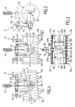
- FIGs 1, 2 and 3 represent an agricultural machine frame 10 on which are mounted two rollers 12a and 12b, for example rollers for seeding, longitudinal axis XX '.
- Each roller comprises a central tube respectively 14a, 14b, mounted on a hub 16a, 16b at the end of an axle 18.
- a series of identical tires 20a, 20b is threaded around each central tube.
- the tires 20a, 20b have a dome circumferential profile which allows the rollers to form grooves on the ground surface, and they are stacked contiguously against one another and held between two flanges. end 22a, 24a and 22b, 24b ensuring the maintenance and tightening of the series of tires ( Figure 3 ).
- the flanges 22a, 24a and 22b, 24b can be dismantled in order to mount or replace the tires. They may further be provided with lugs (not shown) adapted to engage in appropriate recesses of the end tires to lock the tires in rotation relative to the tubes 14a, 14b.
- a transverse disk 26a, 26b is fixed perpendicularly to the inner wall of each of the tubes 14a, 14b in order to fasten each tube 14a, 14b to the two hubs 16a, 16b mounted at the ends of the axle 18, respectively.
- radial gussets 28 are arranged on either side of each of the discs 26a, 26b and are fixed by any known means, between the surfaces of each of the discs 26a, 26b and the inner walls of the tubes 14a, 14b.
- the axle 18 is secured to the support frame by means of a traction leg 30 fixed at one of its ends in the middle of the axle 18 and a connecting piece 32.
- the displacement of the support frame 10 causes, by reaction of the tires 20a, 20b on the ground, the rotation of the rollers 12a, 12b carried out so that the tires, thanks to their dome profile, create in the ground grooves parallel to each other, furrows in which, for example, seeds may be sown.
- the machine which has just been described is adapted to be able not only to work in the field, but also to drive on the road, the tires remaining in contact with the roadway.
- the hubs 16a, 16b are equipped with brakes 34a, 34b drum or disk and the connecting piece 32 is adapted to allow the rollers 12a, 12b to tilt freely from an angle more or less ⁇ ( figure 4 ) about a first axis of articulation YY 'perpendicular to the longitudinal axis of the rollers 12a, 12b and around a second hinge axis HH' direction parallel to the pitch axis of the frame and perpendicular to that of the first hinge axis YY ', to allow the rollers 12a, 12b to remain in contact with the ground regardless of the deformations of the roadway or ground to be seeded encountered.
- ⁇ figure 4
- the connecting piece 32 has the shape of a bracket having a vertical upright 34 and a cross member 36 placed at right angles.
- the connecting piece 32 is articulated at the intersection of the upright 34 and the crosspiece 36 about the second hinge axis HH 'parallel to the pitch axis of the frame 10.
- the traction leg is fixed by one of its ends in the middle of the axle 18 and is engaged by its other end in a thrust bearing 38 of the connecting piece 32 disposed at the end of the upright 34 opposite to that common to the 34 and the cross member 36, which allows it to rotate around the first hinge axis YY '.
- the pulling leg 30 is rotated about the first hinge axis YY 'under the thrust of two cylinders 40a, 40b of the pneumatic or hydraulic type, single or double acting, arranged symmetrically respectively bearing at the ends of a bar support member 42 fixed in the middle at the end of the traction leg 30 opposite that which is fixed to the axle 18 and oriented in a direction parallel to that of the longitudinal axis XX 'of the rollers 12a, 12b.
- the ends of the cylinders 40a, 40b opposite to those bearing on the support bar 42 are fixed to a second support bar 44 integral with the cross member 36 and oriented in a direction parallel to the second axis of articulation HH '.
- a damper 46 is interposed between the free end of the crossmember 36 and the frame 10.
- Figures 1 to 3 correspond to a configuration of the machine that is particularly useful for sowing on land with few irregularities, which is generally the case when the land has been properly prepared before receiving the seedlings.
- the jacks 40a and 40b are locked and have the same elongation.
- the release of the cylinders 40a, 40b allows the longitudinal axis XX 'of the rollers 12a, 12b to take different inclinations of angle of plus or minus ⁇ relative to the second axis of articulation HH' turning around the first reference axis YY ', depending on the irregularities of the roadway.
- the cylinders 40a, 40b have only a damping role similar to that of the damper 46 interposed between the free end of the crossmember 36 and the frame 10.
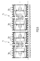
- FIG. 5 is a seedling configuration for which the machine moves on relatively flat ground.
- the axes XX 'of each pair of rollers are aligned and the machine is moving with its jacks blocked.
- the distance between two pairs of rollers P1, P2 and between the rollers 16a, 16b of a pair is determined equal to the pitch X of the circumferential dome profiles of the rollers in order to ensure a smooth working of the ground without leaving space planar continuity between two adjacent grooves dug by two pairs of rollers.
- the length of each roll may be set equal to 0.70 meters with a pitch X circumferential dome profiles of the rollers included, for example, between 100 mm and 200 mm. For a pitch of 125 mm, this corresponds in an exemplary embodiment comprising two pairs of roll rollers to a total length of rolls of about 3 meters.
- the Figures 6 to 8 correspond to road transport configurations of the machine with two pairs of rollers P1, P2 of the figure 5 .
- the machine moves with the jacks 40a, 40b of each pair of unlocked rollers which allows each pair of rollers to adapt to the profile of the roadway.
Landscapes
- Life Sciences & Earth Sciences (AREA)
- Engineering & Computer Science (AREA)
- Mechanical Engineering (AREA)
- Soil Sciences (AREA)
- Environmental Sciences (AREA)
- Soil Working Implements (AREA)
- Tires In General (AREA)
- Sowing (AREA)
Claims (13)
- Landwirtschaftliche Maschine umfassend ein Traggestell (10) und mehrere mit dem Traggestell (10) verbundene Rollen (12a, 12b), wobei zumindest eine der Rollen (12a, 12b) mit dem Traggestell durch ein Verbindungsteil (32) verbunden ist, um dieser zu ermöglichen, sich frei um mindestens eine Gelenkachse zu neigen, dadurch gekennzeichnet, dass sie eine bestimmte Anzahl an jeweils mit dem Traggestell (10) der Maschine über ein Verbindungsteil (32) verbundenen Paaren von Rollen (12a, 12b) umfasst, und dass das Verbindungsteil (32) eines jeden Paars von Rollen angepasst ist, um den Rollen zu ermöglichen, sich frei um eine erste, zu der Längsachse (XX') der Rollen rechtwinklige und koplanare Rollachse (YY') und um eine zweite, zur Nickachse des Traggestells (10) parallele Achse (HH') zu neigen, wie auch immer die anzutreffenden Deformationen der Fahrbahn oder des Bodens sind, wobei jede Rolle (12a, 12b) mit einer Reihe von auf ein Rohr (14a, 14b) aufgezogenen Reifen (20a, 20b) ausgestattet ist und jeweilige umlaufende gewölbte Profile aufweist, die geeignet sind, eine Reihe von Ackerfurchen auf dem Boden zu formen.
- Landwirtschaftliche Maschine nach Anspruch 1, dadurch gekennzeichnet, dass jedes Rohr (14a, 14b) von einem Paar von Rollen auf einer Nabe (16a, 16b) an der Extremität einer Achse (18), deren Längsachse mit der Längsachse (XX') der Rollen (12a, 12b) zusammenfällt, montiert ist.
- Landwirtschaftliche Maschine nach Anspruch 2, dadurch gekennzeichnet, dass die Achse (18) von jedem Paar von Rollen mit dem Traggestell (10) mittels eines Zugbeins (30) zusammengehalten wird, das mit einer seiner Extremitäten in der Mitte der Achse (18) befestigt und mit seiner anderen Extremität in einem auf dem Verbindungsteil (32) befestigten Lageranschlag (38) eingesteckt ist.
- Landwirtschaftliche Maschine nach Anspruch 3, dadurch gekennzeichnet, dass das Verbindungsstück (32) in der Form eines Arms einen Ständer (34) und einen im Anschlagwinkel angeordneten Querträger (36) umfasst und hinsichtlich des Schnitts des Ständers (34) und des Querträgers (36) um eine zur Nickachse des Traggestells (10) parallele Gelenkachse (HH') ausgebildet ist und dass das Zugbein (30) mit seiner Extremität in dem Lageranschlag (38) des Verbindungsteils (32) eingesteckt um die zur Längsachse (XX') der Rollen (12a, 12b) rechtwinklige Rollachse (YY') angeordnet ist.
- Landwirtschaftliche Maschine nach den Ansprüchen 3 und 4, dadurch gekennzeichnet, dass der Lageranschlag (38) auf dem Ständer (34) des Arms (32) an seiner Extremität entgegengesetzt derjenigen mit dem Querträger (36) gemeinsamen Extremität befestigt ist.
- Landwirtschaftliche Maschine nach einem der Ansprüche 4 und 5, dadurch gekennzeichnet, dass das Zugbein (30) um die erste Rollachse (YY') durch zwei Zylinder (40a, 40b), die symmetrisch in der Auflage jeweils an den Extremitäten einer Auflage-Stange (42), die in der Mitte an der Extremität entgegengesetzt derjenigen Extremität, die an der Achse (18) befestigt und in einer Richtung parallel zu der der Längsachse (XX') der Rollen (12a, 12b) orientiert ist, angeordnet sind, in Rotation versetzt wird und dass die der Auflage auf der Auflagestange (42) entgegengesetzten Extremitäten der Zylinder (40a, 40b) an einer zweiten mit dem Querträger (36) verbundenen und einer zur zweiten Gelenkachse (HH') parallelen Richtung folgend orientierten Auflagestange (44) befestigt sind.
- Landwirtschaftliche Maschine nach einem der Ansprüche 4 bis 6, dadurch gekennzeichnet, dass sie einen zwischen der freien Extremität des Querträgers (36) und dem Gestell (10) angeordneten Dämpfer (46) umfasst.
- Landwirtschaftliche Maschine nach einem der Ansprüche 2 bis 7, dadurch gekennzeichnet, dass die Naben (16a, 16b) mit Trommel- oder Scheibenbremsen (34a, 34b) ausgerüstet sind.
- Landwirtschaftliche Maschine nach einem der Ansprüche 1 bis 8, dadurch gekennzeichnet, dass die Reifen (20a, 20b) zwischen zwei die Aufrechterhaltung und die Einspannung der Reihe der Reifen (20a, 20b) sichernden äußeren Flanschen (22a, 24a, 22b, 24b) gehalten sind.
- Landwirtschaftliche Maschine nach Anspruch 9, dadurch gekennzeichnet, dass die Flansche (22a, 24a; 22b, 24b) demontierbar sind, um die Reifen (20a, 20b) zu montieren oder austauschen zu können.
- Landwirtschaftliche Maschine nach einem der Ansprüche 2 bis 10, dadurch gekennzeichnet, dass sie eine Querscheibe (26a, 26b) umfasst, die rechtwinklig an der Innenwand von jedem der Rohre (14a, 14b) befestigt ist, um die Befestigung von jedem Rohr (14a, 14b) jeweils auf den zwei an den Extremitäten der Achse (18) montierten Naben (16a, 16b), zu gewährleisten.
- Landwirtschaftliche Maschine nach Anspruch 11, dadurch gekennzeichnet, dass radiale Taschen (28) auf beiden Seiten von jeder der Scheiben (26a, 26b) angeordnet und zwischen den Oberflächen von jeder der Scheiben (26a, 26b) und der Innenwand von jedem der Rohre (14a, 14b) festgelegt sind.
- Landwirtschaftliche Maschine nach einem der Ansprüche 1 bis 12, dadurch gekennzeichnet, dass die an den beiden Extremitäten der Zusammenstellung der Paare von Rollen angeordneten Paare von Rollen zum Transport auf dem Reiseweg der Maschine um ein am Gestell (10) befestigtes Gelenk angewinkelt sind.
Priority Applications (1)
| Application Number | Priority Date | Filing Date | Title |
|---|---|---|---|
| PL04292499T PL1527665T3 (pl) | 2003-10-27 | 2004-10-21 | Maszyna rolnicza z kadłubem nośnym przyczepnym i rolkami wyposażonymi w serię ogumień o profilu w kształcie kopuły |
Applications Claiming Priority (2)
| Application Number | Priority Date | Filing Date | Title |
|---|---|---|---|
| FR0312539 | 2003-10-27 | ||
| FR0312539A FR2861252B1 (fr) | 2003-10-27 | 2003-10-27 | Machine agricole comportant un bati support tracte et des rouleaux pourvus d'une serie de pneumatiques a profil en dome |
Publications (2)
| Publication Number | Publication Date |
|---|---|
| EP1527665A1 EP1527665A1 (de) | 2005-05-04 |
| EP1527665B1 true EP1527665B1 (de) | 2013-02-20 |
Family
ID=34400814
Family Applications (1)
| Application Number | Title | Priority Date | Filing Date |
|---|---|---|---|
| EP04292499A Expired - Lifetime EP1527665B1 (de) | 2003-10-27 | 2004-10-21 | Landwirtschaftliche Maschine mit gezogenem Gestell und Walzen mit gewölbten Reifen |
Country Status (7)
| Country | Link |
|---|---|
| US (1) | US7124835B2 (de) |
| EP (1) | EP1527665B1 (de) |
| CA (1) | CA2483082C (de) |
| DK (1) | DK1527665T3 (de) |
| ES (1) | ES2407809T3 (de) |
| FR (1) | FR2861252B1 (de) |
| PL (1) | PL1527665T3 (de) |
Families Citing this family (11)
| Publication number | Priority date | Publication date | Assignee | Title |
|---|---|---|---|---|
| GB0413462D0 (en) * | 2004-06-16 | 2004-07-21 | Simba Internat Ltd | A soil treatment apparatus |
| DE202007010209U1 (de) * | 2007-07-23 | 2008-12-04 | Alois Pöttinger Maschinenfabrik Gmbh | Landmaschine |
| ES2372322T3 (es) | 2007-11-02 | 2012-01-18 | Lemken Gmbh & Co. Kg | Combinación de aperos agrícolas replegable. |
| FR2964293B1 (fr) * | 2010-09-03 | 2012-09-07 | Otico | Ensemble de rouleau pour machines agricoles |
| FR2978896B1 (fr) * | 2011-08-12 | 2013-08-09 | Otico | Machine agricole a roue et rouleau adapte |
| GB2496432B (en) * | 2011-11-11 | 2013-12-11 | Brian Mark Thomson | Compactor wheel or roller |
| FR2987715B1 (fr) * | 2012-03-09 | 2014-03-28 | Otico | Machine de modelage du sol a un ou plusieurs rouleaux |
| FR3034283B1 (fr) * | 2015-03-30 | 2017-05-05 | Otico | Pneumatique pour rouleau agricole et rouleau agricole equipe de tels pneumatiques |
| FR3038490B1 (fr) * | 2015-07-10 | 2017-07-21 | Otico | Pneumatique sillonneur |
| US10407842B2 (en) * | 2016-09-08 | 2019-09-10 | Mole Patrol, Llc | Roller devices and systems and methods for using same |
| RU204418U1 (ru) * | 2021-01-29 | 2021-05-24 | Федеральное государственное бюджетное образовательное учреждение высшего образования "Ульяновский государственный аграрный университет имени П.А. Столыпина" | Каток - гребнеобразователь |
Family Cites Families (28)
| Publication number | Priority date | Publication date | Assignee | Title |
|---|---|---|---|---|
| US247698A (en) * | 1881-09-27 | Land-roller | ||
| US85641A (en) * | 1869-01-05 | Improvement in land-rollers | ||
| US201368A (en) * | 1878-03-19 | Improvement in land-rollers | ||
| US649423A (en) * | 1897-09-22 | 1900-05-08 | Clement F Hinman | Road-roller. |
| US634737A (en) * | 1899-08-08 | 1899-10-10 | James W Newman | Land-roller. |
| US681297A (en) * | 1900-01-11 | 1901-08-27 | Fredrick A Bruckman | Land-roller. |
| US694213A (en) * | 1901-06-08 | 1902-02-25 | J Carroll Stark | Land-roller. |
| US976293A (en) * | 1910-06-20 | 1910-11-22 | Charles G Reiff | Farm-roller. |
| US1293600A (en) * | 1914-10-05 | 1919-02-04 | Erastus M Winegarner | Roller. |
| US1607672A (en) * | 1925-08-13 | 1926-11-23 | William D Gray | Crop roller |
| US1843110A (en) * | 1929-08-30 | 1932-02-02 | Harry O Cooper | Furrow packing machine |
| US1842717A (en) * | 1930-05-20 | 1932-01-26 | Patrick A Doyle | Snow roller for roads |
| US2587463A (en) * | 1946-06-22 | 1952-02-26 | Wm Bros Boiler & Mfg Co | Tamping roller frame |
| US2640405A (en) * | 1951-11-19 | 1953-06-02 | Wheeler Gerald Elza | Implement hitch |
| US2798419A (en) * | 1954-05-04 | 1957-07-09 | Harry Ferguson De France | Disc tiller construction |
| DE1995748U (de) * | 1968-06-14 | 1968-10-31 | Hofmann Maschf Geb | Dreiteilige ackerwalze. |
| US4043400A (en) * | 1972-06-23 | 1977-08-23 | C. Van Der Lely N. V. | Harrows |
| US4168750A (en) * | 1976-09-16 | 1979-09-25 | Combs William M | Agricultural roller |
| CH604787A5 (de) * | 1977-01-28 | 1978-09-15 | Josef Neff | |
| DE3033905A1 (de) * | 1980-09-09 | 1982-04-29 | Bayerische Pflugfabrik Gmbh, 8910 Landsberg | Kruemelwalzenanordnung fuer bodenbearbeitungskombinationen |
| DE3433385A1 (de) * | 1984-09-12 | 1986-03-20 | Benno 5205 St Augustin Kaltenegger | Strassenwalze |
| DE3605975A1 (de) * | 1985-11-04 | 1987-08-27 | Otto Fritz Ulrich Dipl Agr Ing | Nachlaeuferkombination fuer wendepacker |
| DE3634175A1 (de) * | 1986-10-07 | 1988-04-21 | Josef Fliegl | Ackerwalze |
| DE3734521A1 (de) * | 1987-10-13 | 1989-06-01 | Knuth Boedecker | Frontreifenpacker fuer traktoren zum verfestigen des ackerbodens zwischen den traktorraedern |
| FR2763779B1 (fr) | 1997-05-23 | 1999-08-27 | Magneti Marelli France | Plaque electronique pliee a 45° |
| US6119788A (en) * | 1999-05-10 | 2000-09-19 | Bernier; Andre | Foldable agricultural roller |
| FR2799692B1 (fr) * | 1999-10-14 | 2002-08-16 | Otico | Pneumatique du type semi-creux a rigidite et maintien ameliores |
| US6793437B2 (en) * | 2002-09-05 | 2004-09-21 | Glenn O. Hawbaker, Inc. | Side-mounted shoulder compaction roller |
-
2003
- 2003-10-27 FR FR0312539A patent/FR2861252B1/fr not_active Expired - Lifetime
-
2004
- 2004-10-21 US US10/969,059 patent/US7124835B2/en not_active Expired - Lifetime
- 2004-10-21 PL PL04292499T patent/PL1527665T3/pl unknown
- 2004-10-21 ES ES04292499T patent/ES2407809T3/es not_active Expired - Lifetime
- 2004-10-21 DK DK04292499.3T patent/DK1527665T3/da active
- 2004-10-21 EP EP04292499A patent/EP1527665B1/de not_active Expired - Lifetime
- 2004-10-22 CA CA2483082A patent/CA2483082C/fr not_active Expired - Lifetime
Also Published As
| Publication number | Publication date |
|---|---|
| DK1527665T3 (da) | 2013-05-21 |
| FR2861252A1 (fr) | 2005-04-29 |
| CA2483082C (fr) | 2012-05-22 |
| US20050087351A1 (en) | 2005-04-28 |
| PL1527665T3 (pl) | 2013-08-30 |
| FR2861252B1 (fr) | 2006-02-17 |
| CA2483082A1 (fr) | 2005-04-27 |
| ES2407809T3 (es) | 2013-06-14 |
| EP1527665A1 (de) | 2005-05-04 |
| US7124835B2 (en) | 2006-10-24 |
Similar Documents
| Publication | Publication Date | Title |
|---|---|---|
| CA2483077A1 (fr) | Deplacement d'un objet articule virtuel dans un environnement virtuel en evitant les collisions internes entre les elements articules de l'objet articule | |
| CA2483082C (fr) | Machine agricole comportant un bati support tracte et des rouleaux pourvus d'une serie de pneumatiques a profil en dome | |
| FR2467755A1 (fr) | Dispositifs de roulement pour vehicules, en particulier pour chariots de prises de vues de television | |
| WO2011001087A1 (fr) | Vehicule enjambeur automoteur | |
| EP2425697B1 (de) | Walzenanordnung für landwirtschaftliche Maschinen | |
| EP1380198B1 (de) | Landwirtschaftliche Maschine mit gezogenem Gestell und Domreifenwalzen | |
| FR2855714A1 (fr) | Semoir en ligne | |
| EP2534933A1 (de) | Sämaschine mit Verdichtungselementen, die die Transporträder bilden | |
| EP2636289A1 (de) | Maschine zum Bodenformen mit einer oder mehreren Walzen | |
| FR2543787A1 (fr) | Chassis porteur combine avec une machine agricole telle qu'une machine a travailler le sol | |
| FR2632596A1 (fr) | Tracteur | |
| FR2534110A1 (fr) | Dispositif destine a supporter, au moins partiellement, le poids d'une machine agricole | |
| EP1429106B1 (de) | Täuschfahrzeug zur Absicherung einer Fahrstrecke gegen Minen | |
| FR2971408A1 (fr) | Rayonnage mobile et installation de rayonnages mobiles | |
| FR2697128A1 (fr) | Herse rotative. | |
| FR2642876A1 (fr) | Dispositif de simulation des conditions de conduite d'un vehicule automobile a traction avant sur une surface glissante | |
| EP1695603B1 (de) | Bodenbearbeitungs- und Bodenbehandlungsmaschine mit grosser Breite | |
| FR2546122A1 (fr) | Tracteur ou vehicule similaire dont les roues directrices sont egalement motrices | |
| FR2643776A1 (fr) | Dispositif de guidage et de commande d'une machine agricole soumise en service a une forte poussee laterale par rapport a sa direction de traction, telle qu'une dechaumeuse a disques | |
| EP0847683A1 (de) | Grossflächen-Drillmaschine | |
| FR2766325A1 (fr) | Machine pour planter des piquets notamment dans les terrains a vignobles | |
| EP1050203A1 (de) | V-Egge mit umkehrbaren Scheibensätzen | |
| FR2780239A1 (fr) | Semoir comportant des organes de reference et des dispositifs d'appui limitant le deplacement de structures porteuses | |
| EP2299797A1 (de) | Landwirtschaftsfahrzeug | |
| FR2636051A1 (fr) | Cage de roues jumelees pour engin mobile de levage et de pose de grands recipients transportables |
Legal Events
| Date | Code | Title | Description |
|---|---|---|---|
| PUAI | Public reference made under article 153(3) epc to a published international application that has entered the european phase |
Free format text: ORIGINAL CODE: 0009012 |
|
| AK | Designated contracting states |
Kind code of ref document: A1 Designated state(s): AT BE BG CH CY CZ DE DK EE ES FI FR GB GR HU IE IT LI LU MC NL PL PT RO SE SI SK TR |
|
| AX | Request for extension of the european patent |
Extension state: AL HR LT LV MK |
|
| 17P | Request for examination filed |
Effective date: 20051013 |
|
| AKX | Designation fees paid |
Designated state(s): AT BE BG CH CY CZ DE DK EE ES FI FR GB GR HU IE IT LI LU MC NL PL PT RO SE SI SK TR |
|
| 17Q | First examination report despatched |
Effective date: 20081029 |
|
| GRAP | Despatch of communication of intention to grant a patent |
Free format text: ORIGINAL CODE: EPIDOSNIGR1 |
|
| GRAS | Grant fee paid |
Free format text: ORIGINAL CODE: EPIDOSNIGR3 |
|
| GRAA | (expected) grant |
Free format text: ORIGINAL CODE: 0009210 |
|
| AK | Designated contracting states |
Kind code of ref document: B1 Designated state(s): AT BE BG CH CY CZ DE DK EE ES FI FR GB GR HU IE IT LI LU MC NL PL PT RO SE SI SK TR |
|
| REG | Reference to a national code |
Ref country code: GB Ref legal event code: FG4D Free format text: NOT ENGLISH |
|
| REG | Reference to a national code |
Ref country code: CH Ref legal event code: EP |
|
| REG | Reference to a national code |
Ref country code: AT Ref legal event code: REF Ref document number: 597089 Country of ref document: AT Kind code of ref document: T Effective date: 20130315 |
|
| REG | Reference to a national code |
Ref country code: IE Ref legal event code: FG4D Free format text: LANGUAGE OF EP DOCUMENT: FRENCH |
|
| REG | Reference to a national code |
Ref country code: DE Ref legal event code: R096 Ref document number: 602004041052 Country of ref document: DE Effective date: 20130418 |
|
| REG | Reference to a national code |
Ref country code: DK Ref legal event code: T3 |
|
| REG | Reference to a national code |
Ref country code: SE Ref legal event code: TRGR |
|
| REG | Reference to a national code |
Ref country code: ES Ref legal event code: FG2A Ref document number: 2407809 Country of ref document: ES Kind code of ref document: T3 Effective date: 20130614 |
|
| REG | Reference to a national code |
Ref country code: NL Ref legal event code: T3 |
|
| PG25 | Lapsed in a contracting state [announced via postgrant information from national office to epo] |
Ref country code: BG Free format text: LAPSE BECAUSE OF FAILURE TO SUBMIT A TRANSLATION OF THE DESCRIPTION OR TO PAY THE FEE WITHIN THE PRESCRIBED TIME-LIMIT Effective date: 20130520 |
|
| REG | Reference to a national code |
Ref country code: SK Ref legal event code: T3 Ref document number: E 14010 Country of ref document: SK |
|
| PG25 | Lapsed in a contracting state [announced via postgrant information from national office to epo] |
Ref country code: PT Free format text: LAPSE BECAUSE OF FAILURE TO SUBMIT A TRANSLATION OF THE DESCRIPTION OR TO PAY THE FEE WITHIN THE PRESCRIBED TIME-LIMIT Effective date: 20130620 Ref country code: SI Free format text: LAPSE BECAUSE OF FAILURE TO SUBMIT A TRANSLATION OF THE DESCRIPTION OR TO PAY THE FEE WITHIN THE PRESCRIBED TIME-LIMIT Effective date: 20130220 Ref country code: GR Free format text: LAPSE BECAUSE OF FAILURE TO SUBMIT A TRANSLATION OF THE DESCRIPTION OR TO PAY THE FEE WITHIN THE PRESCRIBED TIME-LIMIT Effective date: 20130521 |
|
| REG | Reference to a national code |
Ref country code: PL Ref legal event code: T3 |
|
| PG25 | Lapsed in a contracting state [announced via postgrant information from national office to epo] |
Ref country code: RO Free format text: LAPSE BECAUSE OF FAILURE TO SUBMIT A TRANSLATION OF THE DESCRIPTION OR TO PAY THE FEE WITHIN THE PRESCRIBED TIME-LIMIT Effective date: 20130220 Ref country code: EE Free format text: LAPSE BECAUSE OF FAILURE TO SUBMIT A TRANSLATION OF THE DESCRIPTION OR TO PAY THE FEE WITHIN THE PRESCRIBED TIME-LIMIT Effective date: 20130220 |
|
| PG25 | Lapsed in a contracting state [announced via postgrant information from national office to epo] |
Ref country code: CY Free format text: LAPSE BECAUSE OF FAILURE TO SUBMIT A TRANSLATION OF THE DESCRIPTION OR TO PAY THE FEE WITHIN THE PRESCRIBED TIME-LIMIT Effective date: 20130220 |
|
| PLBE | No opposition filed within time limit |
Free format text: ORIGINAL CODE: 0009261 |
|
| STAA | Information on the status of an ep patent application or granted ep patent |
Free format text: STATUS: NO OPPOSITION FILED WITHIN TIME LIMIT |
|
| REG | Reference to a national code |
Ref country code: HU Ref legal event code: AG4A Ref document number: E017959 Country of ref document: HU |
|
| 26N | No opposition filed |
Effective date: 20131121 |
|
| REG | Reference to a national code |
Ref country code: DE Ref legal event code: R097 Ref document number: 602004041052 Country of ref document: DE Effective date: 20131121 |
|
| BERE | Be: lapsed |
Owner name: OTICO Effective date: 20131031 |
|
| PG25 | Lapsed in a contracting state [announced via postgrant information from national office to epo] |
Ref country code: MC Free format text: LAPSE BECAUSE OF FAILURE TO SUBMIT A TRANSLATION OF THE DESCRIPTION OR TO PAY THE FEE WITHIN THE PRESCRIBED TIME-LIMIT Effective date: 20130220 |
|
| REG | Reference to a national code |
Ref country code: CH Ref legal event code: PL |
|
| REG | Reference to a national code |
Ref country code: IE Ref legal event code: MM4A |
|
| PG25 | Lapsed in a contracting state [announced via postgrant information from national office to epo] |
Ref country code: LI Free format text: LAPSE BECAUSE OF NON-PAYMENT OF DUE FEES Effective date: 20131031 Ref country code: CH Free format text: LAPSE BECAUSE OF NON-PAYMENT OF DUE FEES Effective date: 20131031 |
|
| PG25 | Lapsed in a contracting state [announced via postgrant information from national office to epo] |
Ref country code: BE Free format text: LAPSE BECAUSE OF NON-PAYMENT OF DUE FEES Effective date: 20131031 |
|
| PG25 | Lapsed in a contracting state [announced via postgrant information from national office to epo] |
Ref country code: IE Free format text: LAPSE BECAUSE OF NON-PAYMENT OF DUE FEES Effective date: 20131021 |
|
| PG25 | Lapsed in a contracting state [announced via postgrant information from national office to epo] |
Ref country code: TR Free format text: LAPSE BECAUSE OF FAILURE TO SUBMIT A TRANSLATION OF THE DESCRIPTION OR TO PAY THE FEE WITHIN THE PRESCRIBED TIME-LIMIT Effective date: 20130220 |
|
| PG25 | Lapsed in a contracting state [announced via postgrant information from national office to epo] |
Ref country code: LU Free format text: LAPSE BECAUSE OF NON-PAYMENT OF DUE FEES Effective date: 20131021 |
|
| REG | Reference to a national code |
Ref country code: FR Ref legal event code: PLFP Year of fee payment: 12 |
|
| REG | Reference to a national code |
Ref country code: FR Ref legal event code: PLFP Year of fee payment: 13 |
|
| REG | Reference to a national code |
Ref country code: FR Ref legal event code: PLFP Year of fee payment: 14 |
|
| REG | Reference to a national code |
Ref country code: FR Ref legal event code: PLFP Year of fee payment: 15 |
|
| PGFP | Annual fee paid to national office [announced via postgrant information from national office to epo] |
Ref country code: NL Payment date: 20231019 Year of fee payment: 20 |
|
| PGFP | Annual fee paid to national office [announced via postgrant information from national office to epo] |
Ref country code: SK Payment date: 20231013 Year of fee payment: 20 |
|
| PGFP | Annual fee paid to national office [announced via postgrant information from national office to epo] |
Ref country code: GB Payment date: 20231020 Year of fee payment: 20 |
|
| PGFP | Annual fee paid to national office [announced via postgrant information from national office to epo] |
Ref country code: ES Payment date: 20231222 Year of fee payment: 20 |
|
| PGFP | Annual fee paid to national office [announced via postgrant information from national office to epo] |
Ref country code: SE Payment date: 20231019 Year of fee payment: 20 Ref country code: IT Payment date: 20231026 Year of fee payment: 20 Ref country code: HU Payment date: 20231024 Year of fee payment: 20 Ref country code: FR Payment date: 20231009 Year of fee payment: 20 Ref country code: FI Payment date: 20231019 Year of fee payment: 20 Ref country code: DK Payment date: 20231024 Year of fee payment: 20 Ref country code: DE Payment date: 20231020 Year of fee payment: 20 Ref country code: CZ Payment date: 20231012 Year of fee payment: 20 Ref country code: AT Payment date: 20231025 Year of fee payment: 20 |
|
| PGFP | Annual fee paid to national office [announced via postgrant information from national office to epo] |
Ref country code: PL Payment date: 20231013 Year of fee payment: 20 |
|
| REG | Reference to a national code |
Ref country code: DE Ref legal event code: R071 Ref document number: 602004041052 Country of ref document: DE |
|
| REG | Reference to a national code |
Ref country code: NL Ref legal event code: MK Effective date: 20241020 |
|
| REG | Reference to a national code |
Ref country code: ES Ref legal event code: FD2A Effective date: 20241028 Ref country code: DK Ref legal event code: EUP Expiry date: 20241021 |
|
| REG | Reference to a national code |
Ref country code: SK Ref legal event code: MK4A Ref document number: E 14010 Country of ref document: SK Expiry date: 20241021 |
|
| REG | Reference to a national code |
Ref country code: GB Ref legal event code: PE20 Expiry date: 20241020 |
|
| REG | Reference to a national code |
Ref country code: SE Ref legal event code: EUG |
|
| REG | Reference to a national code |
Ref country code: AT Ref legal event code: MK07 Ref document number: 597089 Country of ref document: AT Kind code of ref document: T Effective date: 20241021 |
|
| PG25 | Lapsed in a contracting state [announced via postgrant information from national office to epo] |
Ref country code: GB Free format text: LAPSE BECAUSE OF EXPIRATION OF PROTECTION Effective date: 20241020 |
|
| PG25 | Lapsed in a contracting state [announced via postgrant information from national office to epo] |
Ref country code: CZ Free format text: LAPSE BECAUSE OF EXPIRATION OF PROTECTION Effective date: 20241021 |
|
| PG25 | Lapsed in a contracting state [announced via postgrant information from national office to epo] |
Ref country code: SK Free format text: LAPSE BECAUSE OF EXPIRATION OF PROTECTION Effective date: 20241021 |
|
| PG25 | Lapsed in a contracting state [announced via postgrant information from national office to epo] |
Ref country code: ES Free format text: LAPSE BECAUSE OF EXPIRATION OF PROTECTION Effective date: 20241022 |
|
| PG25 | Lapsed in a contracting state [announced via postgrant information from national office to epo] |
Ref country code: SK Free format text: LAPSE BECAUSE OF EXPIRATION OF PROTECTION Effective date: 20241021 Ref country code: GB Free format text: LAPSE BECAUSE OF EXPIRATION OF PROTECTION Effective date: 20241020 Ref country code: ES Free format text: LAPSE BECAUSE OF EXPIRATION OF PROTECTION Effective date: 20241022 Ref country code: CZ Free format text: LAPSE BECAUSE OF EXPIRATION OF PROTECTION Effective date: 20241021 |