EP1527375B1 - Procede et dispositif pour minimiser le transfert de toner indesirable dans une station de transfert d'une imprimante electrographique - Google Patents
Procede et dispositif pour minimiser le transfert de toner indesirable dans une station de transfert d'une imprimante electrographique Download PDFInfo
- Publication number
- EP1527375B1 EP1527375B1 EP03747868A EP03747868A EP1527375B1 EP 1527375 B1 EP1527375 B1 EP 1527375B1 EP 03747868 A EP03747868 A EP 03747868A EP 03747868 A EP03747868 A EP 03747868A EP 1527375 B1 EP1527375 B1 EP 1527375B1
- Authority
- EP
- European Patent Office
- Prior art keywords
- toner
- transfer printing
- residual toner
- light
- sensitive medium
- Prior art date
- Legal status (The legal status is an assumption and is not a legal conclusion. Google has not performed a legal analysis and makes no representation as to the accuracy of the status listed.)
- Expired - Lifetime
Links
Images



Classifications
-
- G—PHYSICS
- G03—PHOTOGRAPHY; CINEMATOGRAPHY; ANALOGOUS TECHNIQUES USING WAVES OTHER THAN OPTICAL WAVES; ELECTROGRAPHY; HOLOGRAPHY
- G03G—ELECTROGRAPHY; ELECTROPHOTOGRAPHY; MAGNETOGRAPHY
- G03G15/00—Apparatus for electrographic processes using a charge pattern
- G03G15/14—Apparatus for electrographic processes using a charge pattern for transferring a pattern to a second base
- G03G15/16—Apparatus for electrographic processes using a charge pattern for transferring a pattern to a second base of a toner pattern, e.g. a powder pattern, e.g. magnetic transfer
Definitions
- the invention relates to a method and a device for printing information by means of an electrographic printing device.
- printing devices are known in a variety of forms, for example as electrophotographic printing devices, as ionographic printing devices or as magnetographic printing devices, each with different physical effects are exploited to initially produce a virtual image on an intermediate image carrier, with suitable dye, especially toner to color and to print the image thus generated on a recording medium.
- JP. 2001-324841 JP 2002-156,893 and US 4,903,081 disclosed.
- a transfer printing station comprises a photosensitive medium on which a toner image adheres by means of electrostatic forces caused by an electrical potential, and a conveyor belt, on which for the purpose of transferring the toner image from the rindempflindlichen medium on a sheet-shaped recording medium of the recording medium by means of electrostatic forces is held.
- the transfer takes place by means of electrostatic forces, which is caused by the potential of the toner image opposite electrical Umtikpotential.
- the electrical Umtikprotential is degraded, while a lying between two recording media gap passes the photosensitive medium. Due to the temporary reduction of the transfer printing potential, it is possible to produce a toner mark in the intermediate space on the photosensitive medium, wherein this toner is printed on the conveyor belt to an insignificant extent.
- Such toner marks are useful for regularly adjusting electrographic parameters, but should not be re-printed on the record carriers as much as possible.
- the invention provides a solution to perform toner brands on the one hand performant, i. without being able to reduce the printing speed, to be able to use and on the other hand avoid a disturbing transfer of the same.
- a control device which derives from the image sequences of the electrographic recording process, at which times no record carrier bears against the photosensitive medium and then causes the degradation of the transfer printing potential.
- the conveyor belt has, in particular, an electrical volume resistance greater than 10 10 ⁇ cm, whereby the transfer potential also causes the electrostatic forces to hold the recording medium.
- Both the photosensitive medium and the conveyor belt may be provided with cleaning stations which effect a continuous cleaning of toner particles still remaining on the respective element.
- the cleaning stations may further comprise mechanically permanently contacting, by which the toner particles are scraped off.
- photosensitive medium is preferably softer material such. As rubber or soft plastic, provided while cleaning the more robust conveyor belt harder material such.
- the residual toner containers at the two cleaning stations are in particular designed so that they become full at average attack of residual amounts of toner in the two cleaning stations about the same time. In this case, it is sufficient only at one of the two containers to arrange a level sensor, which is displayed to the operator of the device, when the remaining toner containers are to be emptied or replaced with empty containers.
- the invention thus provides an arrangement with which the accumulation of residual toner in an electrographic device can be specifically directed into certain processing channels, whereby in particular a compact design can be realized by arrangements are provided for the removal of residual toner, the transport the waste toner to suitable places, where sufficient space for residual toner containers is available and / or the containers are easily accessible from the outside.
- the invention makes it possible to process a small amount of residual toner in a confined space of a recording medium transport belt and to process comparatively more residual toner in a comparatively larger space, such as the cleaning station of a photoconductive drum.
- FIG. 1 an electrophotographic printing apparatus 21 is shown, in which individual, sheet-shaped recording medium made of paper from a paper input in a first printing unit 24 and / or in a second printing unit 25 can be printed and then to a paper output 26 for storage in output trays and / or for further processing in can be transported to other paper sheet processing equipment.
- Each of the two printing units 24, 25 in this case has a transfer station 3a or 3b, in the toner images, which are deposited on a photoconductor drum, are imprinted on the paper sheet.
- the printing device 21 has a second paper input 23, which largely corresponds to the paper input 22 in terms of its mechanical and electrical construction and paper sheets through the paper input 22 to one or both of the printing units 24, 25 can be handed over for printing.
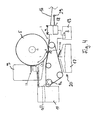
- FIG. 2 a transfer station 3 is shown a little more detail.
- a paper sheet 1 is fed via transport rollers 2 a paper conveyor belt 4.
- the paper transport belt 4 is charged by means of a transfer loading station 8 to a high electrical potential of 2... 5 KV, whereby the paper sheet 1 adheres electrostatically to the paper transport belt 4.
- the paper transport belt 4 transports the paper sheet 1 in the direction A, wherein the paper sheet 1 within an angular segment ⁇ , the so-called nip angle, the photoconductive drum 5 wraps around. This in turn moves in the direction B at the same speed as the paper sheet 1 or the conveyor belt 4.
- the underside of the paper transport belt 4 is acted upon by a charge opposite to the charged toner image on the photoconductor drum 5 electrical charge.
- the high-impedance (> 10 10 ⁇ cm) designed paper transport band 4 stores the charge energy This causes on the one hand the toner transfer from the photoconductive drum 5 to the paper sheet and on the other hand a falling over the time t holding force of the paper sheet 1 on the paper transport belt 4.
- the paper transport belt 4 is kept constantly at tension and pressed in the nip area under tension to the photoconductor drum 5.
- an electrostatically held toner image is formed as follows: First, the photoconductor drum 5 is charged to a high voltage with a loading station 6. Then, in an exposure station 7 pointwise, for example, applied by an LED comb or a laser information and thus pointwise discharge zones on the photoconductor drum 5 is created. Toner then deposits on these loading zones, which is stored in a developer station 29 and prepared for attachment to the photoconductor drum 5.
- Toner is transferred to the paper transport belt only in cases where image information exists outside the record carrier format or in which toner marks have been generated in the spaces between successive record carriers on the photoconductive drum.
- the residual toner on the paper transport belt thus results in: ⁇ transfer ⁇ Image information and background outside the record carrier format + toner mark ,
- the photoconductor cleaning station 9 comprises a to be operated with AC (AC) corona 9a through which the positively charged residual toner, which is still after the transfer printing on the photoconductor drum 5, is electrically neutralized. This minimizes the electrostatic holding forces between toner and photoconductor layer.
- the discharged toner is stripped off by means of a sliding rubber lip 11 of the photoconductor drum 5, collected in a collecting container 12 and then transported by a conveyor 13 in a readily accessible from the outside residual toner container 14 outside the Umtikaggregats.
- the level of the residual toner container 14 is monitored by means of a level sensor 15. From a certain level of the container, the operator is asked via a printer control panel to replace the container. If this is not done within a certain time, the printing process stops automatically to avoid overfilling the container.
- the blade 16 is arranged directly over a second residual toner container 17, so that the scraped-off toner particles fall directly into the residual toner container 17. If the residual toner container 17 is full, it must also be emptied or exchanged for an empty container. If the level of the residual toner container 17 is not monitored, the replacement of the container should be synchronized with the residual toner container 14 of the photoconductor cleaning station 9.
- the volume of this container must be chosen so large that its maximum capacity does not exceed the maximum capacity of the monitored residual toner container 14 in the photoconductor cleaning station 9. This requires a relatively large volume, which requires a considerable space in the area of the paper transport belt and is hardly feasible in a compact design of the printing system. It could also be provided to change the second residual toner container 17 as a function of page counters. However, this may mean that the container must be replaced relatively often, which on the one hand increases the consumption costs and on the other requires a formal intervention of the operator and thus leads to more frequent print interruption, which is unacceptable in a print production environment.
- the residual amount of toner on the paper conveyor belt is reduced, in which in the interstices of the individual sides to be printed (gap) the current for the transfer charge in the loading station 8 is turned off.
- the FIGS. 4 and 5 show how this can be done.
- the control device 18 has an interface 29, via which it determines from an imaging unit, for example from the exposure unit 7 or an upstream image processing unit, from which the page sequence is derived and the power supply 19, with which the transfer loading station is supplied, wearing. Within the distance of successive sides 1a, 1b over the length a while the power supply is turned off ( FIG. 5 ), it is turned on during printing ( FIG. 4 ).
- the distribution of the amount of residual toner produced is thus dependent on the status of the transfer current:
- the transfer efficiency ⁇ Transfer determines the ratio of the residual toner quantity on photoconductor to belt.
- Remaining toner on paper conveyor ⁇ transfer (image information and background outside the format width) + ⁇ mech (image information and background in the gap + toner mark).
- the maximum volume of the residual toner container of the belt cleaning 17 can be adjusted to that of the photoconductor cleaning in the ratio 1: 1, since the maximum residual toner volume on the belt does not exceed the volume of the residual toner on the photoconductor.
- the information such as the level sensor 15 of the remainder toner container of the photoconductive cleaning 14, also be used for the replacement of the residual toner container of the belt cleaning 17. The operator then receives a request to exchange both containers at the same time and to acknowledge.
Landscapes
- Physics & Mathematics (AREA)
- General Physics & Mathematics (AREA)
- Electrostatic Charge, Transfer And Separation In Electrography (AREA)
- Cleaning In Electrography (AREA)
Claims (20)
- Procédé d'exploitation d'une station de transfert (3, 3a, 3b) d'un appareil d'impression électrographique (21), ladite station de transfert (3, 3a, 3b) comportant un moyen photosensible (5) sur lequel des images successives formées par du toner sont fixées sous l'action de forces électrostatiques qui sont générées par un potentiel électrique, ainsi qu'une bande transporteuse (4) sur laquelle le support d'information (1, 1a, 1b) à imprimer est maintenu par des forces électrostatiques afin de transférer les images formées par du toner du moyen photosensible (5) sur des supports d'information (1, 1a, 1b) successifs se présentant sous la forme de feuilles, et le transfert étant effectué par l'action de forces électrostatiques qui sont générées par un potentiel de transfert électrique opposé au potentiel de l'image à transférer formée par du toner, le potentiel de transfert électrique étant arrêté pendant qu'un moyen photosensible (5) passe par un espace intermédiaire (a, gap) entre deux supports d'information successifs (1, 1a, 1b), et un repère de toner étant généré dans l'espace intermédiaire (a, gap) sur le moyen photosensible (5),
une station de nettoyage (9) étant prévue au niveau du moyen photosensible (5), laquelle élimine le toner résiduel non transféré, et ladite station de nettoyage (9) possédant un réservoir de toner résiduel (12, 14) qui reçoit les particules de toner éliminées du moyen photosensible (5),
du toner résiduel étant détaché mécaniquement et en continu de la bande transporteuse (4) par un dispositif de nettoyage (16) prévu au niveau de la bande transporteuse (4), et tombant dans un réservoir de toner résiduel (17) associé à la bande transporteuse (4), et
un capteur de quantité de toner (15) étant disposé seulement au niveau de l'un des deux réservoirs de toner résiduel (12, 14 ; 17), et un signal de cadran étant délivré à l'utilisateur pour échanger les deux réservoirs de toner résiduel lorsque le capteur de quantité de toner (15) délivre un signal « Plein ». - Procédé selon la revendication 1, dans lequel on utilise un dispositif de commande (18) qui déduit des suites d'images du processus d'enregistrement électrographique à quels instants aucun support d'information (1, 1a, 1b) ne porte contre le moyen photosensible (5), et on arrête ensuite le potentiel de transfert.
- Procédé selon la revendication 1 ou 2, dans lequel la bande transporteuse (4) a une résistivité électrique supérieure à 1010 Ωcm, permettant au potentiel de transfert de générer également les forces électrostatiques destinées à maintenir le support d'information (1, 1a, 1b).
- Procédé selon l'une des revendications précédentes, dans lequel la station de nettoyage (9) comporte un dispositif de décharge (9a) sollicité par un courant alternatif et/ou un élément de nettoyage (11) à contact mécanique qui porte en permanence contre le moyen photosensible.
- Procédé selon la revendication 4, dans lequel l'élément de nettoyage (11) à contact mécanique est une lèvre en caoutchouc.
- Procédé selon l'une des revendications précédentes, dans lequel le capteur de quantité de toner (15) est prévu dans la station de nettoyage (9), et délivre un signal « Plein » lorsqu'une quantité prédéterminée de particules de toner est atteinte dans le réservoir de toner résiduel (14).
- Procédé selon la revendication 6, dans lequel il est prévu un dispositif de transport (13) permettant de transporter des particules de toner éliminées jusque dans le réservoir de toner résiduel (14).
- Procédé selon l'une des revendications précédentes, dans lequel le dispositif de nettoyage (16) prévu au niveau de la bande transporteuse (4) comporte une lame flexible ou une lame de céramique rigide (16).
- Procédé selon l'une des revendications précédentes, dans lequel, après la délivrance du signal « Plein » du capteur de quantité de toner (15), le récipient de toner résiduel (14) de la station de nettoyage du moyen photosensible ainsi que le récipient de toner résiduel (17) de la bande transporteuse sont vidés ou sont remplacés par un récipient vide.
- Procédé selon l'une des revendications précédentes, dans lequel on utilise comme moyen photosensible (5) un tambour photoconducteur rotatif dont la vitesse circonférentielle est égale, lors du transfert, à la vitesse de transport de la bande transporteuse (4).
- Station de transfert (3, 3a, 3b) d'un appareil d'impression électrographique (21), ladite station de transfert comportant un moyen photosensible (5) sur lequel des images formées par du toner peuvent être fixées sous l'action de forces électrostatiques qui sont générées par un potentiel électrique, ainsi qu'une bande transporteuse (4) sur laquelle les supports d'information (1, 1a, 1b) à imprimer peuvent être maintenus par des forces électrostatique afin de transférer les images formées par du toner du moyen photosensible (5) sur des supports d'information (1, 1a, 1b) successifs se présentant sous la forme de feuilles, le transfert étant effectué par l'action de forces électrostatiques qui sont générées par un potentiel de transfert électrique opposé au potentiel de l'image à transférer formée par du toner, et un dispositif de commande étant prévu qui permet d'arrêter le potentiel de transfert électrique pendant qu'un moyen photosensible (5) passe par un espace intermédiaire (gap) entre des supports d'information successifs (1, 1a, 1b),
une station de nettoyage (9) étant prévue au niveau du moyen photosensible (5), laquelle élimine le toner résiduel non transféré, et ladite station de nettoyage (9) possédant un réservoir de toner résiduel (12, 14) qui reçoit les particules de toner éliminées du moyen photosensible (5),
du toner résiduel étant détaché mécaniquement et en continu de la bande transporteuse (4) par un dispositif de nettoyage (16) prévu au niveau de la bande transporteuse (4), et tombant dans un réservoir de toner résiduel (17) associé à la bande transporteuse (4), et
un capteur de quantité de toner (15) étant disposé seulement au niveau de l'un des deux réservoirs de toner résiduel (12, 14 ; 17), et un signal de cadran étant délivré à l'utilisateur pour échanger les deux réservoirs de toner résiduel lorsque le capteur de quantité de toner (15) délivre un signal « Plein ». - Station de transfert selon la revendication 11, dans lequel on utilise un dispositif de commande (18) qui déduit des suites d'images du processus d'enregistrement électrographique à quels instants aucun support d'information (1, 1a, 1b) ne porte contre le moyen photosensible (5), et on arrête ensuite le potentiel de transfert.
- Station de transfert selon la revendication 11 ou 12, dans lequel la bande transporteuse (4) a une résistivité électrique supérieure à 1010 Ωcm, permettant au potentiel de transfert de générer également les forces électrostatiques destinées à maintenir le support d'information (1, 1a, 1b).
- Station de transfert selon l'une des revendications 11 à 13, dans lequel la station de nettoyage (9) comporte un dispositif de décharge (9a) sollicité par un courant alternatif et/ou un élément de nettoyage (11) à contact mécanique qui porte en permanence contre le moyen photosensible.
- Station de transfert selon la revendication 14, dans lequel l'élément de nettoyage (11) à contact mécanique est une lèvre en caoutchouc.
- Station de transfert selon l'une des revendications 11 à 15, dans lequel le capteur de quantité de toner (15) est prévu dans la station de nettoyage (9), et délivre un signal « Plein » lorsqu'une quantité prédéterminée de particules de toner est atteinte dans le réservoir de toner résiduel (14).
- Station de transfert selon la revendication 16, dans lequel il est prévu un dispositif de transport (13) permettant de transporter des particules de toner éliminées jusque dans le réservoir de toner résiduel (14).
- Station de transfert selon l'une des revendications 11 à 17, dans lequel le dispositif de nettoyage (16) prévu au niveau de la bande transporteuse (4) comporte une lame flexible ou une lame de céramique rigide (16).
- Procédé selon l'une des revendications 11 à 18, dans lequel les deux récipients de toner résiduel (14, 17) sont conformés de telle sorte que, après la délivrance du signal « Plein » du capteur de quantité de toner (15), le récipient de toner résiduel (14) de la station de nettoyage du moyen photosensible ainsi que le récipient de toner résiduel (17) de la bande transporteuse sont vidés ou sont remplacés par un récipient vide.
- Station de transfert selon l'une des revendications 11 à 19, dans lequel on utilise comme moyen photosensible (5) un tambour photoconducteur rotatif dont la vitesse circonférentielle est égale, lors du transfert, à la vitesse de transport de la bande transporteuse (4).
Applications Claiming Priority (3)
| Application Number | Priority Date | Filing Date | Title |
|---|---|---|---|
| DE10234711 | 2002-07-30 | ||
| DE10234711A DE10234711A1 (de) | 2002-07-30 | 2002-07-30 | Verfahren und Vorrichtung zur Minimierung von unerwünschtem Tonerübertrag in einer Umdruckstation eines elektrografischen Druckgeräts |
| PCT/EP2003/008381 WO2004013701A2 (fr) | 2002-07-30 | 2003-07-29 | Procede et dispositif pour minimiser le transfert de toner indesirable dans une station de report d'une imprimante electrographique |
Publications (2)
| Publication Number | Publication Date |
|---|---|
| EP1527375A2 EP1527375A2 (fr) | 2005-05-04 |
| EP1527375B1 true EP1527375B1 (fr) | 2010-04-07 |
Family
ID=30128524
Family Applications (1)
| Application Number | Title | Priority Date | Filing Date |
|---|---|---|---|
| EP03747868A Expired - Lifetime EP1527375B1 (fr) | 2002-07-30 | 2003-07-29 | Procede et dispositif pour minimiser le transfert de toner indesirable dans une station de transfert d'une imprimante electrographique |
Country Status (5)
| Country | Link |
|---|---|
| US (1) | US7376365B2 (fr) |
| EP (1) | EP1527375B1 (fr) |
| JP (1) | JP4040624B2 (fr) |
| DE (2) | DE10234711A1 (fr) |
| WO (1) | WO2004013701A2 (fr) |
Families Citing this family (4)
| Publication number | Priority date | Publication date | Assignee | Title |
|---|---|---|---|---|
| JP3938150B2 (ja) * | 2004-01-29 | 2007-06-27 | キヤノン株式会社 | 画像形成装置 |
| JP4519787B2 (ja) * | 2006-02-28 | 2010-08-04 | 京セラミタ株式会社 | 画像形成装置 |
| JP4930079B2 (ja) * | 2007-02-01 | 2012-05-09 | コニカミノルタビジネステクノロジーズ株式会社 | 画像形成装置 |
| JP6686343B2 (ja) * | 2015-09-24 | 2020-04-22 | 富士ゼロックス株式会社 | 定着装置および画像形成装置 |
Family Cites Families (17)
| Publication number | Priority date | Publication date | Assignee | Title |
|---|---|---|---|---|
| JPH01149079A (ja) | 1987-12-07 | 1989-06-12 | Ricoh Co Ltd | 転写装置 |
| US5168313A (en) * | 1988-04-28 | 1992-12-01 | Kabushiki Kaisha Toshiba | Toner image transfer method and device for electrophotographic printing apparatus |
| JPH08227259A (ja) | 1994-11-14 | 1996-09-03 | Konica Corp | 画像形成装置 |
| JP3403594B2 (ja) * | 1995-11-15 | 2003-05-06 | 株式会社リコー | 画像形成装置 |
| JPH1138796A (ja) * | 1997-07-15 | 1999-02-12 | Toshiba Corp | 画像形成装置 |
| JPH11194675A (ja) * | 1998-01-06 | 1999-07-21 | Casio Electron Mfg Co Ltd | 画像形成装置 |
| JP2002509291A (ja) | 1998-01-16 | 2002-03-26 | オーセ プリンティング システムズ ゲゼルシャフト ミットベシュレンクテル ハフツング | 少なくとも2つの測定個所においてトナーマークが走査される、印刷またはコピーのための装置及び方法 |
| JPH11265090A (ja) * | 1998-03-18 | 1999-09-28 | Canon Inc | 画像形成方法 |
| JP2000122499A (ja) * | 1998-10-16 | 2000-04-28 | Sharp Corp | 画像形成装置 |
| JP2000275983A (ja) * | 1999-03-24 | 2000-10-06 | Toshiba Tec Corp | 転写装置、及びこの転写装置を備えた画像形成装置 |
| JP3893236B2 (ja) * | 1999-07-08 | 2007-03-14 | キヤノン株式会社 | 画像形成装置 |
| JP2001324841A (ja) | 2000-05-16 | 2001-11-22 | Fuji Xerox Co Ltd | 画像形成装置 |
| JP2001324905A (ja) * | 2000-05-17 | 2001-11-22 | Matsushita Electric Ind Co Ltd | 画像形成装置 |
| US6631249B2 (en) * | 2000-09-29 | 2003-10-07 | Canon Kabushiki Kaisha | Image forming apparatus capable of preventing the overflow of toner on a clean blade |
| JP2002156843A (ja) | 2000-11-17 | 2002-05-31 | Konica Corp | 画像形成装置 |
| US6600894B2 (en) | 2000-11-30 | 2003-07-29 | Kabushiki Kaisha Toshiba | Method and apparatus for forming image, and method for absorbing transcriptional material |
| JP4708557B2 (ja) * | 2000-12-26 | 2011-06-22 | キヤノン株式会社 | 画像形成装置 |
-
2002
- 2002-07-30 DE DE10234711A patent/DE10234711A1/de not_active Withdrawn
-
2003
- 2003-07-29 JP JP2004525369A patent/JP4040624B2/ja not_active Expired - Fee Related
- 2003-07-29 DE DE50312596T patent/DE50312596D1/de not_active Expired - Lifetime
- 2003-07-29 US US10/523,200 patent/US7376365B2/en not_active Expired - Fee Related
- 2003-07-29 EP EP03747868A patent/EP1527375B1/fr not_active Expired - Lifetime
- 2003-07-29 WO PCT/EP2003/008381 patent/WO2004013701A2/fr not_active Ceased
Also Published As
| Publication number | Publication date |
|---|---|
| DE50312596D1 (de) | 2010-05-20 |
| US7376365B2 (en) | 2008-05-20 |
| JP4040624B2 (ja) | 2008-01-30 |
| WO2004013701A2 (fr) | 2004-02-12 |
| JP2006501491A (ja) | 2006-01-12 |
| WO2004013701A3 (fr) | 2004-04-08 |
| EP1527375A2 (fr) | 2005-05-04 |
| US20060013601A1 (en) | 2006-01-19 |
| DE10234711A1 (de) | 2004-02-12 |
Similar Documents
| Publication | Publication Date | Title |
|---|---|---|
| DE4420667C2 (de) | Spannungsreinigungssystem, elektrostatische Druckvorrichtung und Verfahren zum Betrieb des Systems und der Vorrichtung | |
| DE19618905C2 (de) | Elektrostatische Bilderzeugungseinrichtung | |
| DE68913789T2 (de) | Aufladevorrichtung und Bilderzeugungsgerät mit dieser. | |
| DE69927324T2 (de) | Bilderzeugungsgerät | |
| DE60034208T2 (de) | Bilderzeugungsgerät | |
| DE69412217T2 (de) | Anpassungsfähige Schmierung für Reinigungsklinge | |
| EP1110125B1 (fr) | Imprimante ou photocopieur pour impression simultanee sur deux faces d'un materiau support | |
| DE19617152A1 (de) | Entwicklungseinrichtung für ein elektrophotographisches Aufzeichnungsgerät | |
| DE69419850T2 (de) | Elektrostatisches Reinigen nichtgescheuerter Elektronendrähte mittels Gleichspannung | |
| DE19617149A1 (de) | Elektrophotographisches Aufzeichnungsgerät | |
| DE69015059T2 (de) | Vorrichtung zur Aussonderung von falsch geladenem Toner bei einem direkten elektrostatischen Druckgerät. | |
| DE10351219A1 (de) | Übertragung von Toner mit einem zeitvariablen Übertragungsstationsstrom | |
| DE60219787T2 (de) | ENTWICKLUNGSEINRICHTUNG mit elektrischem Feld in Form von Wanderwellen | |
| DE10034905B4 (de) | Bestimmung des Photoleiterverschleisses | |
| DE69815728T2 (de) | Bilderzeugungsgerät | |
| DE60001078T2 (de) | Bilderzeugungsgerät mit vorübergehender Staubentfernung von den anderen photoemfindlichen Trommeln im Einfarbenbetrieb | |
| EP1527375B1 (fr) | Procede et dispositif pour minimiser le transfert de toner indesirable dans une station de transfert d'une imprimante electrographique | |
| EP1179754B1 (fr) | Programme d'isolation de processus pour un appareil électrophographique de marquage | |
| DE69014411T2 (de) | Aufzeichnungsgerät. | |
| DE69713053T2 (de) | Bilderzeugungsgerät | |
| DE10210806A1 (de) | Verbesserte Übertragungswalzenreinigung | |
| DE3436648C2 (fr) | ||
| DE69212532T2 (de) | Elektrophotographisches Druckgerät | |
| DE69021934T2 (de) | Nassaufnahmegerät. | |
| US8019249B2 (en) | Charging device, image forming apparatus and method of charging image carrier of image forming apparatus |
Legal Events
| Date | Code | Title | Description |
|---|---|---|---|
| PUAI | Public reference made under article 153(3) epc to a published international application that has entered the european phase |
Free format text: ORIGINAL CODE: 0009012 |
|
| 17P | Request for examination filed |
Effective date: 20050228 |
|
| AK | Designated contracting states |
Kind code of ref document: A2 Designated state(s): AT BE BG CH CY CZ DE DK EE ES FI FR GB GR HU IE IT LI LU MC NL PT RO SE SI SK TR |
|
| RBV | Designated contracting states (corrected) |
Designated state(s): DE FR GB |
|
| GRAP | Despatch of communication of intention to grant a patent |
Free format text: ORIGINAL CODE: EPIDOSNIGR1 |
|
| GRAS | Grant fee paid |
Free format text: ORIGINAL CODE: EPIDOSNIGR3 |
|
| GRAA | (expected) grant |
Free format text: ORIGINAL CODE: 0009210 |
|
| AK | Designated contracting states |
Kind code of ref document: B1 Designated state(s): DE FR GB |
|
| REG | Reference to a national code |
Ref country code: GB Ref legal event code: FG4D Free format text: NOT ENGLISH |
|
| REF | Corresponds to: |
Ref document number: 50312596 Country of ref document: DE Date of ref document: 20100520 Kind code of ref document: P |
|
| PLBE | No opposition filed within time limit |
Free format text: ORIGINAL CODE: 0009261 |
|
| STAA | Information on the status of an ep patent application or granted ep patent |
Free format text: STATUS: NO OPPOSITION FILED WITHIN TIME LIMIT |
|
| 26N | No opposition filed |
Effective date: 20110110 |
|
| GBPC | Gb: european patent ceased through non-payment of renewal fee |
Effective date: 20100729 |
|
| REG | Reference to a national code |
Ref country code: FR Ref legal event code: ST Effective date: 20110331 |
|
| PG25 | Lapsed in a contracting state [announced via postgrant information from national office to epo] |
Ref country code: FR Free format text: LAPSE BECAUSE OF NON-PAYMENT OF DUE FEES Effective date: 20100802 |
|
| PG25 | Lapsed in a contracting state [announced via postgrant information from national office to epo] |
Ref country code: GB Free format text: LAPSE BECAUSE OF NON-PAYMENT OF DUE FEES Effective date: 20100729 |
|
| REG | Reference to a national code |
Ref country code: DE Ref legal event code: R082 Ref document number: 50312596 Country of ref document: DE Representative=s name: PATENTANWAELTE SCHAUMBURG, THOENES, THURN, LAN, DE |
|
| REG | Reference to a national code |
Ref country code: DE Ref legal event code: R081 Ref document number: 50312596 Country of ref document: DE Owner name: OCE PRINTING SYSTEMS GMBH & CO. KG, DE Free format text: FORMER OWNER: OCE PRINTING SYSTEMS GMBH, 85586 POING, DE Effective date: 20130819 Ref country code: DE Ref legal event code: R082 Ref document number: 50312596 Country of ref document: DE Representative=s name: PATENTANWAELTE SCHAUMBURG, THOENES, THURN, LAN, DE Effective date: 20130819 Ref country code: DE Ref legal event code: R082 Ref document number: 50312596 Country of ref document: DE Representative=s name: SCHAUMBURG & PARTNER PATENTANWAELTE GBR, DE Effective date: 20130819 Ref country code: DE Ref legal event code: R082 Ref document number: 50312596 Country of ref document: DE Representative=s name: SCHAUMBURG & PARTNER PATENTANWAELTE MBB, DE Effective date: 20130819 Ref country code: DE Ref legal event code: R082 Ref document number: 50312596 Country of ref document: DE Representative=s name: SCHAUMBURG UND PARTNER PATENTANWAELTE MBB, DE Effective date: 20130819 |
|
| PGFP | Annual fee paid to national office [announced via postgrant information from national office to epo] |
Ref country code: DE Payment date: 20140826 Year of fee payment: 12 |
|
| REG | Reference to a national code |
Ref country code: DE Ref legal event code: R082 Ref document number: 50312596 Country of ref document: DE Representative=s name: SCHAUMBURG & PARTNER PATENTANWAELTE GBR, DE Ref country code: DE Ref legal event code: R082 Ref document number: 50312596 Country of ref document: DE Representative=s name: SCHAUMBURG & PARTNER PATENTANWAELTE MBB, DE Ref country code: DE Ref legal event code: R082 Ref document number: 50312596 Country of ref document: DE Representative=s name: SCHAUMBURG UND PARTNER PATENTANWAELTE MBB, DE |
|
| REG | Reference to a national code |
Ref country code: DE Ref legal event code: R119 Ref document number: 50312596 Country of ref document: DE |
|
| PG25 | Lapsed in a contracting state [announced via postgrant information from national office to epo] |
Ref country code: DE Free format text: LAPSE BECAUSE OF NON-PAYMENT OF DUE FEES Effective date: 20160202 |