EP1526768B1 - Ensemble transmission - Google Patents
Ensemble transmission Download PDFInfo
- Publication number
- EP1526768B1 EP1526768B1 EP03792183A EP03792183A EP1526768B1 EP 1526768 B1 EP1526768 B1 EP 1526768B1 EP 03792183 A EP03792183 A EP 03792183A EP 03792183 A EP03792183 A EP 03792183A EP 1526768 B1 EP1526768 B1 EP 1526768B1
- Authority
- EP
- European Patent Office
- Prior art keywords
- drive shaft
- transmission
- drive
- input shaft
- polygonal
- Prior art date
- Legal status (The legal status is an assumption and is not a legal conclusion. Google has not performed a legal analysis and makes no representation as to the accuracy of the status listed.)
- Expired - Lifetime
Links
- 230000005540 biological transmission Effects 0.000 claims abstract description 40
- 230000008878 coupling Effects 0.000 claims description 13
- 238000010168 coupling process Methods 0.000 claims description 13
- 238000005859 coupling reaction Methods 0.000 claims description 13
- 238000009331 sowing Methods 0.000 claims description 3
- 235000013339 cereals Nutrition 0.000 claims 1
- 238000003780 insertion Methods 0.000 description 11
- 230000037431 insertion Effects 0.000 description 11
- 238000012546 transfer Methods 0.000 description 3
- 239000000356 contaminant Substances 0.000 description 2
- 239000002184 metal Substances 0.000 description 2
- 230000001419 dependent effect Effects 0.000 description 1
- 238000013461 design Methods 0.000 description 1
- 238000001514 detection method Methods 0.000 description 1
- 238000011161 development Methods 0.000 description 1
- 230000018109 developmental process Effects 0.000 description 1
- 238000006073 displacement reaction Methods 0.000 description 1
- 238000012986 modification Methods 0.000 description 1
- 230000004048 modification Effects 0.000 description 1
- 238000010899 nucleation Methods 0.000 description 1
- 230000002093 peripheral effect Effects 0.000 description 1
Images

Classifications
-
- F—MECHANICAL ENGINEERING; LIGHTING; HEATING; WEAPONS; BLASTING
- F16—ENGINEERING ELEMENTS AND UNITS; GENERAL MEASURES FOR PRODUCING AND MAINTAINING EFFECTIVE FUNCTIONING OF MACHINES OR INSTALLATIONS; THERMAL INSULATION IN GENERAL
- F16D—COUPLINGS FOR TRANSMITTING ROTATION; CLUTCHES; BRAKES
- F16D1/00—Couplings for rigidly connecting two coaxial shafts or other movable machine elements
- F16D1/06—Couplings for rigidly connecting two coaxial shafts or other movable machine elements for attachment of a member on a shaft or on a shaft-end
- F16D1/08—Couplings for rigidly connecting two coaxial shafts or other movable machine elements for attachment of a member on a shaft or on a shaft-end with clamping hub; with hub and longitudinal key
- F16D1/0894—Couplings for rigidly connecting two coaxial shafts or other movable machine elements for attachment of a member on a shaft or on a shaft-end with clamping hub; with hub and longitudinal key with other than axial keys, e.g. diametral pins, cotter pins and no other radial clamping
-
- A—HUMAN NECESSITIES
- A01—AGRICULTURE; FORESTRY; ANIMAL HUSBANDRY; HUNTING; TRAPPING; FISHING
- A01C—PLANTING; SOWING; FERTILISING
- A01C19/00—Arrangements for driving working parts of fertilisers or seeders
Definitions
- the invention relates to a transmission arrangement for driving an auxiliary device, with an input shaft connected to the auxiliary device and with a transmission, which has a transmission output, which is provided with a rotational output movement supplying polygonal drive opening, and a drive coupling containing drive shaft.
- the drive coupling includes an annular, axially extending bore which receives the input shaft, with an easily detachable pin extending between the input shaft and the input shaft, which drives the input shaft to drive the input shaft.
- Flexible rotatable drive shafts are used in various applications to transfer torques from one location to another.
- flexible rotatable drive shafts include a male connector to engage a female connector on a transmission.
- the flexible rotatable drive shaft is in driving connection with the transmission.
- the transmission is drivingly coupled to a driven member by a gear assembly.
- One possibility is to decouple the flexible rotatable drive shaft from the transmission. It is disadvantageous that the plug-shaped connecting element of the flexible drive shaft at a Such decoupling is exposed to dirt and other contaminants.
- the object underlying the invention is seen to provide a gear assembly of the type mentioned, by which the aforementioned problems are overcome.
- a gear arrangement of the type mentioned is provided with a polygonal sleeve which is mounted and secured on the drive shaft, wherein the polygonal sleeve is received by the drive opening and engages drivingly in the transmission.
- the gear assembly includes a drive coupling, which in the embodiment has an annular axially extending bore into which is formed a spindle formed as an input shaft of an auxiliary device.
- the gear assembly is coupled to the input shaft of a powered device.
- the gear assembly includes a drive shaft on which a polygonal sleeve is mounted. The polygonal sleeve is pinned to the drive shaft via a split pin. The splint defines a torque transfer limit and thereby provides a torque lock.
- the bore is provided with aligned, transversely extending and bore-passing openings.
- the spindle is also provided with a transversely extending bore which is aligned with the transversely extending openings on the drive coupling.
- An easily detachable connecting pin inserted through the mutually aligned openings and the bore thereby drivingly couples the drive coupling to the input shaft.
- the pin is a spring pin.
- the polygonal sleeve is a hexagonal sleeve.
- the hexagon sleeve is driven by a transmission output.
- the transmission output is provided with a hexagonal drive opening into which the hexagonal sleeve is received.
- a transmission driven by a flexible drive shaft is coupled via a gear arrangement to a metering device.
- the input shaft is the spindle of a metering device, wherein the spindle is received in the bore of the drive coupling.
- a planter 10 includes a single row saw assembly which is mounted to a transverse tool carrier (not shown) by means of U-shaped screws which engage a mounting plate 12.
- the sowing unit is provided with a frame 14 which is coupled via a parallelogram linkage 16 to the mounting plate 12.
- the parallelogram linkage allows a limited lifting and lowering of the sowing unit relative to the tool carrier.
- Seed is automatically fed to the seeding unit through a pneumatic on-demand seed delivery system.
- the on-demand seed delivery system pneumatically directs the seed from a main hopper (not shown) through a seed line 18 to an auxiliary canister 20 mounted on the frame 14.
- the seed in the auxiliary can 20 is metered by a metering device 22 and passed through a seed tube into a seed furrow (not shown).
- the seed furrow is formed by a double disc furrow opener 24 with depth adjustment wheels 26.
- the depth of the seed furrow is adjusted by positioning the lever 28, with which the vertical position of the Tiefeneinsteller 26 is adjustable relative to the furrow opener 24.
- the seed furrow with the metered seed deposited therein through the seed tube is closed by means of furrow closing wheels 30.
- a previously mounted Scheibensech 32 is used for crushing plant residues before they hit the furrow opener 24.
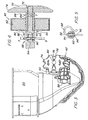
- the metering device 22 is driven by a flexible rotatable drive shaft 40, which drives a gearbox 42.
- the flexible and rotatable drive shaft 40 corresponds to a design as manufactured and marketed by the Elliot Manifacturing Company, LLC, Bermingham, New York.
- a traction-driven transmission (not shown) provides input torque to the flexible drive shaft 40. In this way, the speed of the metering device 22 is controlled by the travel speed of the drill 10.
- the flexible rotatable drive shaft includes a flexible jacket and a rotatable inner core.
- the end of the flexible rotatable drive shaft 40 is provided with a male connector 44 which includes a male sleeve 46 and a rotatable male drive member 48 provided with a flat surface.
- the insertion sleeve 46 is formed as a metal bush, wherein the metal bushing includes a circumferential groove 50.
- the transmission 42 includes a transmission housing 43 having an insertion portion 58 which receives the insertion sleeve 46 and a gear portion 60, the gears 62, 64 receives.
- the gear portion 60 of the housing 43 two helical gears 62, 64 are mounted.
- the first helical gear 62 is drivingly coupled to the metering device 22 by a drive member 80.
- the second helical gear 64 is drivingly coupled to the first helical gear 62.
- the second helical gear 64 is provided with a multi-edged bore which receives the.
- Drive plug 48 of the flexible rotatable drive shaft 40 When the drive shaft 40 is in its engaged position, as shown in FIG Fig. 2 is shown, the second helical gear 64 is driven by the flexible rotatable drive shaft 40.
- the cylindrical insertion portion 58 is provided with a locking device 66 which includes a transverse pin.
- the bolt is rotatably positioned in a transverse bore, which is located in the insertion region 58 of the transmission housing 43.
- the bolt includes a first end with two gripping surfaces 72 for detection by an operator.
- the bolt can be rotated in a locked position and in a release position. To move the bolt between positions, an operator grips the gripping surfaces 72 and pushes the bolt inward. The bolt is then turned to the desired position.
- the bolt includes a peripheral surface defining the locking position and a recessed area defining the release position.
- the circumferential surface engages the circumferential groove 50 and locks the rotatable drive shaft 40 in its engaged position.
- the release position the recessed area releases the insertion sleeve 46 and allows an axial displacement of the insertion sleeve 46 within the insertion region 58 of the transmission housing 43 until it is decoupled from the transmission.
- the insertion sleeve 46 may be provided with visible markings. When the mark is aligned with the edge of the male portion 58 of the gear housing 43, the circumferential groove 50 of the male sheath 46 is in a correct axial position for engagement by the circumferential surface of the stud.
- the drive member 80 includes a drive shaft 82 on which a polygonal sleeve 84 is mounted.
- the polygonal sleeve 84 is connected via a splint 86 with the drive shaft 82nd pinned.
- the splint 86 defines a torque transfer limit and thereby provides a torque lock.
- the polygonal sleeve 84 is a hexagonal sleeve.
- the hexagonal sleeve 84 is driven by a transmission output, which is defined by a polygonal opening in the gear 62, in which the hexagonal sleeve 84 is received.
- the drive shaft 82 is provided with a drive coupling 88.
- the drive coupling 88 includes an annular axially extending bore 90 with aligned openings 92 extending transversely through the bore 90.
- the drive coupling 88 is connected to an input shaft of a powered device.
- the input shaft is formed as a spindle 94 of a metering device 22. The spindle 94 is received in the bore 90.
- the spindle 94 is also provided with a transversely extending bore 96 which is aligned with the laterally extending openings 92 on the drive coupling 88.
- An easily releasable terminal pin 98 is inserted through the aligned openings 92 and through the bore 96, thereby drivingly connecting the drive coupling 88 to the input shaft.
- the pin 98 is a spring pin.
- an operating knob 74 is drivingly connected to the drive shaft 82.
- this knob 74 can be used to the second helical gear. 64 to move so that it detects the drive plug 48 when it is inserted into the transmission housing 43.
- the operation knob 74 is drivingly connected via a pin 76 to the drive shaft 82, which is fixed in a formed on the outer surface of the operating knob 74 recess 78.
- the operator When an operator needs to disconnect the driveline from the flexible rotatable drive shaft 40 and metering device 22, the operator removes the easily detachable terminal pin 98 and then removes the drive member 80 by pulling on the operating knob 74. The drive member 80 and easily detachable terminal pin 98 can then be stored until the metering device 22 has to be reconnected.
Landscapes
- Life Sciences & Earth Sciences (AREA)
- Engineering & Computer Science (AREA)
- General Engineering & Computer Science (AREA)
- Soil Sciences (AREA)
- Environmental Sciences (AREA)
- Mechanical Engineering (AREA)
- Sowing (AREA)
- General Details Of Gearings (AREA)
- Fertilizing (AREA)
- Gear Transmission (AREA)
- Agricultural Machines (AREA)
Abstract
Claims (8)
- Ensemble de transmission pour l'entraînement d'un appareil auxiliaire (22), avec un arbre d'entrée (94) relié à l'appareil auxiliaire (22) et avec une transmission (42), qui présente une sortie de transmission, qui est dotée d'une ouverture d'entraînement polygonale produisant un mouvement de sortie rotatif, et un arbre d'entraînement (82) comportant un accouplement d'entraînement (88), dans lequel l'accouplement d'entraînement (88) comprend un alésage annulaire s'étendant axialement (90), qui contient l'arbre d'entrée (94) et dans lequel une goupille d'assemblage (98) aisément amovible s'étend entre l'arbre d'entraînement (82) et l'arbre d'entrée (94), laquelle solidarise en mouvement d'entraînement l'arbre d'entraînement (82) avec l'arbre d'entrée (94), caractérisé en ce qu'une douille polygonale (84) est montée et est fixée sur l'arbre d'entraînement (82), dans lequel la douille polygonale (84) est logée dans l'ouverture d'entraînement et s'engage en mouvement d'entraînement dans la transmission (42).
- Ensemble de transmission selon la revendication 1, caractérisé en ce que la douille polygonale (84) est fixée sur l'arbre d'entraînement (82) au moyen d'une goupille de cisaillement (86), au moyen de laquelle on définit une limite de transmission de couple de rotation.
- Ensemble de transmission selon la revendication 1 ou 2, caractérisé en ce que l'arbre d'entraînement (82) est pourvu de deux ouvertures (92) s'étendant transversalement à proximité de l'alésage s'étendant axialement (90) et l'arbre d'entrée (94) est pourvu d'un alésage s'étendant transversalement (96), qui est aligné avec les ouvertures s'étendant transversalement (92), afin de recevoir la goupille d'assemblage aisément amovible (98).
- Ensemble de transmission selon l'une quelconque des revendications précédentes, caractérisé en ce qu'il comporte un bouton de commande (74), qui est monté sur l'arbre d'entraînement (82).
- Ensemble de transmission selon la revendication 4, caractérisé en ce que le bouton de commande (74) est monté au moyen d'une goupille fendue (76).
- Ensemble de transmission selon l'une quelconque des revendications précédentes, caractérisé en ce que la douille polygonale (84) est une douille hexagonale.
- Ensemble de transmission selon l'une quelconque des revendications précédentes, caractérisé en ce que l'ouverture d'entraînement polygonale est une ouverture hexagonale.
- Semoir (10) pour planter des céréales, avec un châssis (14), un dispositif de dosage (22) monté sur le châssis pour le dosage des semences à planter, dans lequel le dispositif de dosage (22) comprend un arbre d'entrée (94), avec un soc sillonneur (24) monté sur le châssis (14), qui forme un sillon de plantation sur un champ, dans lequel les semences dosées sont conduites à partir du dispositif de dosage (22), et avec une transmission (42) montée sur le châssis (14), dans lequel la transmission (42) est entraînée par un arbre d'entraînement rotatif flexible (40) et est reliée activement à l'arbre d'entrée (94) du dispositif de dosage (22) par un ensemble de transmission selon l'une quelconque des revendications 1 à 7.
Applications Claiming Priority (3)
| Application Number | Priority Date | Filing Date | Title |
|---|---|---|---|
| US10/214,969 US6745710B2 (en) | 2002-08-08 | 2002-08-08 | Drive element for gearbox output |
| US214969 | 2002-08-08 | ||
| PCT/EP2003/007371 WO2004017714A1 (fr) | 2002-08-08 | 2003-07-09 | Ensemble transmission |
Publications (2)
| Publication Number | Publication Date |
|---|---|
| EP1526768A1 EP1526768A1 (fr) | 2005-05-04 |
| EP1526768B1 true EP1526768B1 (fr) | 2010-12-29 |
Family
ID=31494756
Family Applications (1)
| Application Number | Title | Priority Date | Filing Date |
|---|---|---|---|
| EP03792183A Expired - Lifetime EP1526768B1 (fr) | 2002-08-08 | 2003-07-09 | Ensemble transmission |
Country Status (12)
| Country | Link |
|---|---|
| US (1) | US6745710B2 (fr) |
| EP (1) | EP1526768B1 (fr) |
| AR (1) | AR042765A1 (fr) |
| AU (1) | AU2003250920A1 (fr) |
| BR (1) | BR0302602B1 (fr) |
| CA (1) | CA2435780C (fr) |
| DE (1) | DE50313370D1 (fr) |
| ES (1) | ES2358646T3 (fr) |
| PL (1) | PL211166B1 (fr) |
| RU (1) | RU2329636C2 (fr) |
| UA (1) | UA81426C2 (fr) |
| WO (1) | WO2004017714A1 (fr) |
Families Citing this family (13)
| Publication number | Priority date | Publication date | Assignee | Title |
|---|---|---|---|---|
| US7374029B1 (en) | 2006-12-29 | 2008-05-20 | Jeff Dillman | Actuating device for a drive arrangement |
| DE102007009084A1 (de) * | 2007-02-24 | 2008-08-28 | John Deere Brasil Ltda | Antriebsanordnung zum Antreiben eines Gerätes an einer Bodenbearbeitungsmaschine |
| US7735438B2 (en) * | 2007-10-05 | 2010-06-15 | Deere & Company | Ground driven seed metering system with a continuously variable transmission |
| US7571688B1 (en) * | 2008-04-03 | 2009-08-11 | Deere & Company | Integrated clutches for a seeding machine |
| US8151718B2 (en) * | 2009-05-20 | 2012-04-10 | Deere & Company | Adjustable seed meter drive coupling |
| DE102010014448A1 (de) * | 2010-04-09 | 2011-10-13 | Horsch Maschinen Gmbh | Sämaschine für Einzelkornsaat |
| CA2864157A1 (fr) * | 2012-02-10 | 2013-08-15 | Actuant Corporation | Systeme d'entrainement de dispositif doseur de semences pour semoir a deux rangees |
| CN108207252A (zh) * | 2012-09-11 | 2018-06-29 | 埃克特温特股份有限公司 | 可反向的播种机变速器和播种机驱动设备 |
| USD748154S1 (en) * | 2014-12-15 | 2016-01-26 | Deere & Company | Self-aligning axial drive coupling member |
| USD748155S1 (en) * | 2014-12-15 | 2016-01-26 | Deere & Company | Self-aligning axial drive coupling member |
| US11019762B2 (en) * | 2018-07-12 | 2021-06-01 | Cnh Industrial Canada, Ltd. | Precision depth control of seed planting units of an agricultural implement |
| CN111955080B (zh) * | 2020-08-27 | 2022-06-28 | 塔里木大学 | 一种棉花种植用培土施肥一体装置 |
| CN112772065B (zh) * | 2021-01-25 | 2024-04-09 | 宁夏回族自治区原种场 | 一种用于小区域的四行小麦、水稻播种机 |
Family Cites Families (8)
| Publication number | Priority date | Publication date | Assignee | Title |
|---|---|---|---|---|
| US718664A (en) | 1902-08-23 | 1903-01-20 | Andrew Shearer | Combined lister-plow and planter. |
| GB899733A (en) | 1957-10-28 | 1962-06-27 | Massey Ferguson Sa | Improvements in or relating to seed drills or the like agricultural implements |
| GB1274673A (en) | 1968-10-03 | 1972-05-17 | Massey Ferguson Perkins Ltd | Improvements in metering devices |
| GB2094122B (en) | 1981-03-06 | 1985-01-23 | Massey Ferguson Perkins Ltd | Agricultural drills |
| US4779471A (en) | 1987-03-26 | 1988-10-25 | Deere & Company | Flexible drive arrangement for an implement |
| US5024173A (en) * | 1990-01-29 | 1991-06-18 | Kinze Manufacturing, Inc. | Clutch for chemical dispenser for planter |
| JPH0965701A (ja) | 1995-08-29 | 1997-03-11 | Shigeki Sano | 耕耘機における耕耘軸 |
| FR2820605B1 (fr) * | 2001-02-12 | 2003-09-19 | Kuhn Nodet Sa | Semoir agricole |
-
2002
- 2002-08-08 US US10/214,969 patent/US6745710B2/en not_active Expired - Lifetime
-
2003
- 2003-07-09 RU RU2005106289/11A patent/RU2329636C2/ru not_active IP Right Cessation
- 2003-07-09 EP EP03792183A patent/EP1526768B1/fr not_active Expired - Lifetime
- 2003-07-09 DE DE50313370T patent/DE50313370D1/de not_active Expired - Lifetime
- 2003-07-09 WO PCT/EP2003/007371 patent/WO2004017714A1/fr not_active Ceased
- 2003-07-09 AU AU2003250920A patent/AU2003250920A1/en not_active Abandoned
- 2003-07-09 PL PL373404A patent/PL211166B1/pl not_active IP Right Cessation
- 2003-07-09 UA UAA200501226A patent/UA81426C2/xx unknown
- 2003-07-09 ES ES03792183T patent/ES2358646T3/es not_active Expired - Lifetime
- 2003-07-22 CA CA002435780A patent/CA2435780C/fr not_active Expired - Fee Related
- 2003-07-30 BR BRPI0302602-7A patent/BR0302602B1/pt active IP Right Grant
- 2003-08-08 AR ARP030102861A patent/AR042765A1/es active IP Right Grant
Also Published As
| Publication number | Publication date |
|---|---|
| RU2329636C2 (ru) | 2008-07-27 |
| EP1526768A1 (fr) | 2005-05-04 |
| BR0302602B1 (pt) | 2011-06-28 |
| RU2005106289A (ru) | 2005-08-10 |
| AR042765A1 (es) | 2005-07-06 |
| WO2004017714A1 (fr) | 2004-03-04 |
| US6745710B2 (en) | 2004-06-08 |
| US20040025765A1 (en) | 2004-02-12 |
| PL211166B1 (pl) | 2012-04-30 |
| UA81426C2 (en) | 2008-01-10 |
| AU2003250920A1 (en) | 2004-03-11 |
| PL373404A1 (en) | 2005-08-22 |
| CA2435780C (fr) | 2006-07-18 |
| DE50313370D1 (de) | 2011-02-10 |
| ES2358646T3 (es) | 2011-05-12 |
| BR0302602A (pt) | 2005-04-05 |
| CA2435780A1 (fr) | 2004-02-08 |
Similar Documents
| Publication | Publication Date | Title |
|---|---|---|
| EP1526767B1 (fr) | Mecanisme de transmission, semoir et reservoir de semences equipes d'un tel mecanisme | |
| EP1526768B1 (fr) | Ensemble transmission | |
| EP0747606B1 (fr) | Serrure pour fixation d'un manchon d'accouplement | |
| DE7618758U1 (de) | Rohrschraubenschluessel | |
| EP0178252A2 (fr) | Outil de vissage motorisé | |
| EP1925196A2 (fr) | Semoir | |
| EP1388678B1 (fr) | Combinaison d'une transmission et d'un arbre de commande flexible | |
| EP0577981A2 (fr) | Tête pour une pièce à main médicale ou dentaire comportant un outil de traitement oscillant | |
| EP3918898B1 (fr) | Engin agricole | |
| EP1084603B1 (fr) | Sémoir à débit de semence réglable | |
| EP3918897A1 (fr) | Dispositif de dosage, en particulier pour un semoir | |
| AT413747B (de) | Winkelgetriebe mit integrierter drehspielkupplung | |
| DE2927031B2 (de) | Sämaschine | |
| DE2610989C3 (de) | Drehschrauber | |
| EP0663547B1 (fr) | Entraínement motorisé et pignon à tourillon et dispositif pour le montage ou démontage le pignon | |
| DE1947102A1 (de) | Elektrisch angetriebener Ratschen-Schraubschluessel | |
| EP4342277A1 (fr) | Semoir et procédé de distribution de semences | |
| DE2807521C3 (de) | An einen Schlepper ankuppelbare Drillmaschine | |
| EP1101964A1 (fr) | Accouplement de surcharge | |
| DE60106677T2 (de) | Sämaschine | |
| AT389971B (de) | Saemaschine | |
| EP0140318A1 (fr) | Dispositif de déplacement en hauteur d'un organe pour semer en lignes | |
| DE10329809B4 (de) | Kupplung zur Drehmomentbegrenzung | |
| DE3017506C2 (fr) | ||
| EP1568916B1 (fr) | Transmission à roues dentées interchangeables |
Legal Events
| Date | Code | Title | Description |
|---|---|---|---|
| PUAI | Public reference made under article 153(3) epc to a published international application that has entered the european phase |
Free format text: ORIGINAL CODE: 0009012 |
|
| 17P | Request for examination filed |
Effective date: 20041117 |
|
| AK | Designated contracting states |
Kind code of ref document: A1 Designated state(s): AT BE BG CH CY CZ DE DK EE ES FI FR GB GR HU IE IT LI LU MC NL PT RO SE SI SK TR |
|
| AX | Request for extension of the european patent |
Extension state: AL LT LV MK |
|
| DAX | Request for extension of the european patent (deleted) | ||
| RBV | Designated contracting states (corrected) |
Designated state(s): DE ES FR HU IT |
|
| GRAP | Despatch of communication of intention to grant a patent |
Free format text: ORIGINAL CODE: EPIDOSNIGR1 |
|
| GRAS | Grant fee paid |
Free format text: ORIGINAL CODE: EPIDOSNIGR3 |
|
| GRAA | (expected) grant |
Free format text: ORIGINAL CODE: 0009210 |
|
| AK | Designated contracting states |
Kind code of ref document: B1 Designated state(s): DE ES FR HU IT |
|
| REF | Corresponds to: |
Ref document number: 50313370 Country of ref document: DE Date of ref document: 20110210 Kind code of ref document: P |
|
| REG | Reference to a national code |
Ref country code: DE Ref legal event code: R096 Ref document number: 50313370 Country of ref document: DE Effective date: 20110210 |
|
| REG | Reference to a national code |
Ref country code: ES Ref legal event code: FG2A Ref document number: 2358646 Country of ref document: ES Kind code of ref document: T3 Effective date: 20110429 |
|
| PLBE | No opposition filed within time limit |
Free format text: ORIGINAL CODE: 0009261 |
|
| STAA | Information on the status of an ep patent application or granted ep patent |
Free format text: STATUS: NO OPPOSITION FILED WITHIN TIME LIMIT |
|
| 26N | No opposition filed |
Effective date: 20110930 |
|
| REG | Reference to a national code |
Ref country code: DE Ref legal event code: R097 Ref document number: 50313370 Country of ref document: DE Effective date: 20110930 |
|
| PG25 | Lapsed in a contracting state [announced via postgrant information from national office to epo] |
Ref country code: DE Free format text: LAPSE BECAUSE OF NON-PAYMENT OF DUE FEES Effective date: 20120201 |
|
| REG | Reference to a national code |
Ref country code: DE Ref legal event code: R119 Ref document number: 50313370 Country of ref document: DE Effective date: 20120201 |
|
| PG25 | Lapsed in a contracting state [announced via postgrant information from national office to epo] |
Ref country code: HU Free format text: LAPSE BECAUSE OF FAILURE TO SUBMIT A TRANSLATION OF THE DESCRIPTION OR TO PAY THE FEE WITHIN THE PRESCRIBED TIME-LIMIT Effective date: 20101229 |
|
| REG | Reference to a national code |
Ref country code: FR Ref legal event code: PLFP Year of fee payment: 14 |
|
| PGFP | Annual fee paid to national office [announced via postgrant information from national office to epo] |
Ref country code: IT Payment date: 20160722 Year of fee payment: 14 |
|
| REG | Reference to a national code |
Ref country code: FR Ref legal event code: PLFP Year of fee payment: 15 |
|
| REG | Reference to a national code |
Ref country code: FR Ref legal event code: PLFP Year of fee payment: 16 |
|
| PG25 | Lapsed in a contracting state [announced via postgrant information from national office to epo] |
Ref country code: IT Free format text: LAPSE BECAUSE OF NON-PAYMENT OF DUE FEES Effective date: 20170709 |
|
| PGFP | Annual fee paid to national office [announced via postgrant information from national office to epo] |
Ref country code: ES Payment date: 20220801 Year of fee payment: 20 |
|
| PGFP | Annual fee paid to national office [announced via postgrant information from national office to epo] |
Ref country code: FR Payment date: 20220725 Year of fee payment: 20 |
|
| REG | Reference to a national code |
Ref country code: ES Ref legal event code: FD2A Effective date: 20230727 |
|
| PG25 | Lapsed in a contracting state [announced via postgrant information from national office to epo] |
Ref country code: ES Free format text: LAPSE BECAUSE OF EXPIRATION OF PROTECTION Effective date: 20230710 |