EP1526564B1 - Lampe aux halogénures de scandium et sodium, et procédé de fabrication - Google Patents
Lampe aux halogénures de scandium et sodium, et procédé de fabrication Download PDFInfo
- Publication number
- EP1526564B1 EP1526564B1 EP04256942A EP04256942A EP1526564B1 EP 1526564 B1 EP1526564 B1 EP 1526564B1 EP 04256942 A EP04256942 A EP 04256942A EP 04256942 A EP04256942 A EP 04256942A EP 1526564 B1 EP1526564 B1 EP 1526564B1
- Authority
- EP
- European Patent Office
- Prior art keywords
- halide
- lamp
- metal
- metal halide
- airtight container
- Prior art date
- Legal status (The legal status is an assumption and is not a legal conclusion. Google has not performed a legal analysis and makes no representation as to the accuracy of the status listed.)
- Expired - Fee Related
Links
- 229910001507 metal halide Inorganic materials 0.000 title claims description 81
- 238000000034 method Methods 0.000 title claims description 22
- 238000004519 manufacturing process Methods 0.000 title claims description 13
- 150000005309 metal halides Chemical class 0.000 claims description 80
- 150000004820 halides Chemical class 0.000 claims description 56
- 239000000463 material Substances 0.000 claims description 50
- 239000011651 chromium Substances 0.000 claims description 48
- 229910052751 metal Inorganic materials 0.000 claims description 44
- 239000002184 metal Substances 0.000 claims description 44
- 238000001228 spectrum Methods 0.000 claims description 30
- QSHDDOUJBYECFT-UHFFFAOYSA-N mercury Chemical compound [Hg] QSHDDOUJBYECFT-UHFFFAOYSA-N 0.000 claims description 24
- 229910052753 mercury Inorganic materials 0.000 claims description 21
- 102100023621 4-hydroxyphenylpyruvate dioxygenase-like protein Human genes 0.000 claims description 20
- 101001048445 Homo sapiens 4-hydroxyphenylpyruvate dioxygenase-like protein Proteins 0.000 claims description 20
- VYZAMTAEIAYCRO-UHFFFAOYSA-N Chromium Chemical compound [Cr] VYZAMTAEIAYCRO-UHFFFAOYSA-N 0.000 claims description 16
- 229910052804 chromium Inorganic materials 0.000 claims description 16
- 229910052706 scandium Inorganic materials 0.000 claims description 15
- SIXSYDAISGFNSX-UHFFFAOYSA-N scandium atom Chemical compound [Sc] SIXSYDAISGFNSX-UHFFFAOYSA-N 0.000 claims description 15
- 239000011734 sodium Substances 0.000 claims description 12
- 239000012535 impurity Substances 0.000 claims description 10
- 230000008569 process Effects 0.000 claims description 10
- 238000010438 heat treatment Methods 0.000 claims description 9
- VYPSYNLAJGMNEJ-UHFFFAOYSA-N silicon dioxide Inorganic materials O=[Si]=O VYPSYNLAJGMNEJ-UHFFFAOYSA-N 0.000 claims description 9
- 229910052738 indium Inorganic materials 0.000 claims description 8
- APFVFJFRJDLVQX-UHFFFAOYSA-N indium atom Chemical compound [In] APFVFJFRJDLVQX-UHFFFAOYSA-N 0.000 claims description 8
- -1 zinc (Zn) halide Chemical class 0.000 claims description 8
- DGAQECJNVWCQMB-PUAWFVPOSA-M Ilexoside XXIX Chemical compound C[C@@H]1CC[C@@]2(CC[C@@]3(C(=CC[C@H]4[C@]3(CC[C@@H]5[C@@]4(CC[C@@H](C5(C)C)OS(=O)(=O)[O-])C)C)[C@@H]2[C@]1(C)O)C)C(=O)O[C@H]6[C@@H]([C@H]([C@@H]([C@H](O6)CO)O)O)O.[Na+] DGAQECJNVWCQMB-PUAWFVPOSA-M 0.000 claims description 6
- 229910052708 sodium Inorganic materials 0.000 claims description 6
- 239000010453 quartz Substances 0.000 claims description 5
- 238000000465 moulding Methods 0.000 claims description 4
- 238000007789 sealing Methods 0.000 description 35
- 239000007789 gas Substances 0.000 description 12
- 229910052724 xenon Inorganic materials 0.000 description 12
- FHNFHKCVQCLJFQ-UHFFFAOYSA-N xenon atom Chemical compound [Xe] FHNFHKCVQCLJFQ-UHFFFAOYSA-N 0.000 description 12
- 150000002739 metals Chemical class 0.000 description 10
- 230000033228 biological regulation Effects 0.000 description 8
- 230000004907 flux Effects 0.000 description 7
- 239000000203 mixture Substances 0.000 description 7
- 238000001514 detection method Methods 0.000 description 5
- 230000009467 reduction Effects 0.000 description 5
- 239000004020 conductor Substances 0.000 description 3
- 238000009826 distribution Methods 0.000 description 3
- WABPQHHGFIMREM-UHFFFAOYSA-N lead(0) Chemical compound [Pb] WABPQHHGFIMREM-UHFFFAOYSA-N 0.000 description 3
- 239000000126 substance Substances 0.000 description 3
- WFKWXMTUELFFGS-UHFFFAOYSA-N tungsten Chemical compound [W] WFKWXMTUELFFGS-UHFFFAOYSA-N 0.000 description 3
- 229910052721 tungsten Inorganic materials 0.000 description 3
- 239000010937 tungsten Substances 0.000 description 3
- UAYWVJHJZHQCIE-UHFFFAOYSA-L zinc iodide Chemical compound I[Zn]I UAYWVJHJZHQCIE-UHFFFAOYSA-L 0.000 description 3
- XKRFYHLGVUSROY-UHFFFAOYSA-N Argon Chemical compound [Ar] XKRFYHLGVUSROY-UHFFFAOYSA-N 0.000 description 2
- XEEYBQQBJWHFJM-UHFFFAOYSA-N Iron Chemical compound [Fe] XEEYBQQBJWHFJM-UHFFFAOYSA-N 0.000 description 2
- ZOKXTWBITQBERF-UHFFFAOYSA-N Molybdenum Chemical compound [Mo] ZOKXTWBITQBERF-UHFFFAOYSA-N 0.000 description 2
- 238000010586 diagram Methods 0.000 description 2
- 230000007613 environmental effect Effects 0.000 description 2
- 239000011521 glass Substances 0.000 description 2
- 229910052736 halogen Inorganic materials 0.000 description 2
- 150000002367 halogens Chemical class 0.000 description 2
- KLRHPHDUDFIRKB-UHFFFAOYSA-M indium(i) bromide Chemical compound [Br-].[In+] KLRHPHDUDFIRKB-UHFFFAOYSA-M 0.000 description 2
- 238000009413 insulation Methods 0.000 description 2
- 150000004694 iodide salts Chemical class 0.000 description 2
- 239000011777 magnesium Substances 0.000 description 2
- 239000011572 manganese Substances 0.000 description 2
- 229910052750 molybdenum Inorganic materials 0.000 description 2
- 239000011733 molybdenum Substances 0.000 description 2
- 230000003287 optical effect Effects 0.000 description 2
- 229910052702 rhenium Inorganic materials 0.000 description 2
- WUAPFZMCVAUBPE-UHFFFAOYSA-N rhenium atom Chemical compound [Re] WUAPFZMCVAUBPE-UHFFFAOYSA-N 0.000 description 2
- 238000003860 storage Methods 0.000 description 2
- 239000010936 titanium Substances 0.000 description 2
- 238000002834 transmittance Methods 0.000 description 2
- 238000003466 welding Methods 0.000 description 2
- ZCYVEMRRCGMTRW-UHFFFAOYSA-N 7553-56-2 Chemical compound [I] ZCYVEMRRCGMTRW-UHFFFAOYSA-N 0.000 description 1
- GYHNNYVSQQEPJS-UHFFFAOYSA-N Gallium Chemical compound [Ga] GYHNNYVSQQEPJS-UHFFFAOYSA-N 0.000 description 1
- UFHFLCQGNIYNRP-UHFFFAOYSA-N Hydrogen Chemical compound [H][H] UFHFLCQGNIYNRP-UHFFFAOYSA-N 0.000 description 1
- 229910021621 Indium(III) iodide Inorganic materials 0.000 description 1
- FYYHWMGAXLPEAU-UHFFFAOYSA-N Magnesium Chemical compound [Mg] FYYHWMGAXLPEAU-UHFFFAOYSA-N 0.000 description 1
- PWHULOQIROXLJO-UHFFFAOYSA-N Manganese Chemical compound [Mn] PWHULOQIROXLJO-UHFFFAOYSA-N 0.000 description 1
- 229910000691 Re alloy Inorganic materials 0.000 description 1
- ATJFFYVFTNAWJD-UHFFFAOYSA-N Tin Chemical compound [Sn] ATJFFYVFTNAWJD-UHFFFAOYSA-N 0.000 description 1
- RTAQQCXQSZGOHL-UHFFFAOYSA-N Titanium Chemical compound [Ti] RTAQQCXQSZGOHL-UHFFFAOYSA-N 0.000 description 1
- 229910052782 aluminium Inorganic materials 0.000 description 1
- XAGFODPZIPBFFR-UHFFFAOYSA-N aluminium Chemical compound [Al] XAGFODPZIPBFFR-UHFFFAOYSA-N 0.000 description 1
- PNEYBMLMFCGWSK-UHFFFAOYSA-N aluminium oxide Inorganic materials [O-2].[O-2].[O-2].[Al+3].[Al+3] PNEYBMLMFCGWSK-UHFFFAOYSA-N 0.000 description 1
- 229910052787 antimony Inorganic materials 0.000 description 1
- WATWJIUSRGPENY-UHFFFAOYSA-N antimony atom Chemical compound [Sb] WATWJIUSRGPENY-UHFFFAOYSA-N 0.000 description 1
- 238000013459 approach Methods 0.000 description 1
- 229910052786 argon Inorganic materials 0.000 description 1
- 230000004323 axial length Effects 0.000 description 1
- 230000008901 benefit Effects 0.000 description 1
- 230000005540 biological transmission Effects 0.000 description 1
- 150000003842 bromide salts Chemical class 0.000 description 1
- 239000000919 ceramic Substances 0.000 description 1
- 239000010941 cobalt Substances 0.000 description 1
- 229910017052 cobalt Inorganic materials 0.000 description 1
- GUTLYIVDDKVIGB-UHFFFAOYSA-N cobalt atom Chemical compound [Co] GUTLYIVDDKVIGB-UHFFFAOYSA-N 0.000 description 1
- 238000001816 cooling Methods 0.000 description 1
- 238000005520 cutting process Methods 0.000 description 1
- 238000013461 design Methods 0.000 description 1
- 238000001035 drying Methods 0.000 description 1
- 230000005684 electric field Effects 0.000 description 1
- 238000000295 emission spectrum Methods 0.000 description 1
- 229910052733 gallium Inorganic materials 0.000 description 1
- 238000009499 grossing Methods 0.000 description 1
- 229910052735 hafnium Inorganic materials 0.000 description 1
- VBJZVLUMGGDVMO-UHFFFAOYSA-N hafnium atom Chemical compound [Hf] VBJZVLUMGGDVMO-UHFFFAOYSA-N 0.000 description 1
- 230000017525 heat dissipation Effects 0.000 description 1
- 239000001257 hydrogen Substances 0.000 description 1
- 229910052739 hydrogen Inorganic materials 0.000 description 1
- 238000003780 insertion Methods 0.000 description 1
- 230000037431 insertion Effects 0.000 description 1
- 239000011630 iodine Substances 0.000 description 1
- 229910052740 iodine Inorganic materials 0.000 description 1
- 229910052743 krypton Inorganic materials 0.000 description 1
- DNNSSWSSYDEUBZ-UHFFFAOYSA-N krypton atom Chemical compound [Kr] DNNSSWSSYDEUBZ-UHFFFAOYSA-N 0.000 description 1
- 230000007774 longterm Effects 0.000 description 1
- 238000004020 luminiscence type Methods 0.000 description 1
- 229910052749 magnesium Inorganic materials 0.000 description 1
- 229910052748 manganese Inorganic materials 0.000 description 1
- 239000013307 optical fiber Substances 0.000 description 1
- 238000006552 photochemical reaction Methods 0.000 description 1
- 229910052761 rare earth metal Inorganic materials 0.000 description 1
- 150000002910 rare earth metals Chemical class 0.000 description 1
- 230000009257 reactivity Effects 0.000 description 1
- 239000011819 refractory material Substances 0.000 description 1
- 238000009877 rendering Methods 0.000 description 1
- DECCZIUVGMLHKQ-UHFFFAOYSA-N rhenium tungsten Chemical compound [W].[Re] DECCZIUVGMLHKQ-UHFFFAOYSA-N 0.000 description 1
- VSZWPYCFIRKVQL-UHFFFAOYSA-N selanylidenegallium;selenium Chemical compound [Se].[Se]=[Ga].[Se]=[Ga] VSZWPYCFIRKVQL-UHFFFAOYSA-N 0.000 description 1
- 230000002123 temporal effect Effects 0.000 description 1
- 230000008719 thickening Effects 0.000 description 1
- 229910052719 titanium Inorganic materials 0.000 description 1
- 238000012546 transfer Methods 0.000 description 1
- RMUKCGUDVKEQPL-UHFFFAOYSA-K triiodoindigane Chemical compound I[In](I)I RMUKCGUDVKEQPL-UHFFFAOYSA-K 0.000 description 1
- 238000009489 vacuum treatment Methods 0.000 description 1
Images

Classifications
-
- H—ELECTRICITY
- H01—ELECTRIC ELEMENTS
- H01J—ELECTRIC DISCHARGE TUBES OR DISCHARGE LAMPS
- H01J9/00—Apparatus or processes specially adapted for the manufacture, installation, removal, maintenance of electric discharge tubes, discharge lamps, or parts thereof; Recovery of material from discharge tubes or lamps
- H01J9/24—Manufacture or joining of vessels, leading-in conductors or bases
- H01J9/245—Manufacture or joining of vessels, leading-in conductors or bases specially adapted for gas discharge tubes or lamps
- H01J9/247—Manufacture or joining of vessels, leading-in conductors or bases specially adapted for gas discharge tubes or lamps specially adapted for gas-discharge lamps
-
- H—ELECTRICITY
- H01—ELECTRIC ELEMENTS
- H01J—ELECTRIC DISCHARGE TUBES OR DISCHARGE LAMPS
- H01J61/00—Gas-discharge or vapour-discharge lamps
- H01J61/02—Details
- H01J61/12—Selection of substances for gas fillings; Specified operating pressure or temperature
- H01J61/125—Selection of substances for gas fillings; Specified operating pressure or temperature having an halogenide as principal component
-
- H—ELECTRICITY
- H01—ELECTRIC ELEMENTS
- H01J—ELECTRIC DISCHARGE TUBES OR DISCHARGE LAMPS
- H01J61/00—Gas-discharge or vapour-discharge lamps
- H01J61/82—Lamps with high-pressure unconstricted discharge having a cold pressure > 400 Torr
- H01J61/827—Metal halide arc lamps
Definitions
- the present invention relates to a metal halide lamp with no mercury sealed therein and a lighting device using this lamp.
- a pair of electrodes are sealed in a discharge space defined in a light-transmitting, airtight container made of refractory materials, and a discharge medium using a metal vapor as a main component is sealed in the container.
- Such electrodes generally have a structure wherein: Their proximal ends are welded to respective metal leaves airtightly buried in a pair of slim sealing portions formed integral with the opposite ends of the airtight container. Their intermediate portions are loosely supported by the respective sealing portions. Further, their distal ends, i.e., electrode main portions, protrude into the discharge space.
- High-pressure discharge lamps are used for various purposes.
- compact high-pressure discharge lamps of a high output used in, for example, vehicle headlights are characterized in that their airtight container has a small internal volume, the pressure of the discharge medium is high during lighting, and the operating temperature is high. Therefore, the influence of impurities discharged from their structural components mounted on or sealed in the airtight container upon the long-term brightness or life of the lamps is relatively high.
- the luminous power output immediately after ignition is lower than a predetermined value.
- power several times higher than in a stable state is supplied at the start of lighting. More specifically, immediately after ignition, a lamp current several times larger than in the stable state is produced between the electrodes, thereby accelerating increase in luminous power to promptly activate the high-pressure lamp. At the same time, the lamp is controlled to be promptly stabilized.
- high-pressure discharge lamps with an internal volume of 0.1cc or less which are used as metal halide lamps for vehicle headlights or spot lights, generally have a structure in which a rare gas, halides of light-emitting metals and mercury are sealed in a light emission tube with a pair of opposing electrodes.
- These high-pressure discharge lamps exhibit a relatively high efficiency and a high color-rendering characteristic. Therefore, they are widely used.
- it has become significantly important also in the field of lighting devices to reduce or stop the use of mercury whose environmental impact is high.
- various proposals have been made for eliminating mercury from metal halide lamps. For example, Jpn. Pat. Appln.
- KOKAI Publication No. 11-238488 discloses a technique for adding, instead of mercury, a material having a high vapor pressure, such as ZnI 2 , to a light-emitting halide material, such as ScI 3 -NaI, thereby acquiring the same electric characteristic and light emission characteristic as those acquired from a mercury-containing lamp.
- a material having a high vapor pressure such as ZnI 2
- a light-emitting halide material such as ScI 3 -NaI
- EP1339090 discloses a metal halide lamp having an electrode structure modified to suppress the luminescence flicker.
- the lamp comprises a hermetic vessel, a pair of electrodes and a discharge medium in which the lamp is turned on with a lamp power of 60W or lower.
- the inventor of the present invention has found that when chromium (Cr), an impurity, exists in the airtight container, it emits light and thins the discharge arc, and that the discharge arc can have a thickness satisfying the regulation if the emission spectrum of chromium is kept at a predetermined value or less.
- the present invention has been developed based on this finding.
- a metal halide lamp comprising:
- the airtight container is refractory and light-transmittable.
- “Refractory” means that the container is strong enough to resist the standard operation temperature of discharge lamps.
- the airtight container may be formed of any material if the material is refractory and can transmit, to the outside thereof, visible light of a desired wavelength area generated by discharge.
- it may be quartz glass or, polycrystal or monocrystal ceramics such as light-transmitting alumina, YAG.
- quartz glass having a high direct transmittance is appropriate since a high light-concentration efficiency is required.
- quartz glass having a high direct transmittance is appropriate since a high light-concentration efficiency is required.
- it is allowed to form, on the inner surface of the airtight container of quartz glass, a light-transmitting film having a resistance against halogens or halides, or to improve the quality of the inner surface of the airtight container.
- the airtight container defines therein a discharge space having an internal volume of 0.1cc or less, preferably, 0.05cc or less.
- the discharge space is a substantial cylinder that has an inner diameter of 1.5 to 3.5mm and an axial length of 5 to 9mm.
- the portion surrounding the discharge space can be made relatively thick.
- the portion located at substantially the intermediate position between the electrodes can be made thicker than the opposite ends.
- the airtight container can be formed integrally as one body with a pair of cylindrical sealing sections so that the sealing sections are located at the respective axially opposite ends of the discharge space.
- the electrodes are connected to external guide wires via the airtightly buried metal leaves.
- a current can be supplied to the electrodes, and the closing section can be formed without an exhaustion tip, thereby avoiding disturbance of the light distribution characteristic due to the exhaustion tip.
- Electrodes The pair of electrodes are sealed in the airtight container, opposing each other with a distance of 0.5mm or less interposed therebetween.
- the electrodes have a linear axial portion having substantially the same diameter in the longitudinal direction.
- the diameter of the axial portion is, preferably, 0.3mm or more, and 0.45mm or less preferably as a metal halide lamp for vehicle headlights.
- the diameter of the axial portion is substantially constant.
- the distal end of each electrode is formed flat, or has a curved surface serving as the starting point of an arc. Alternatively, the distal end may be formed to a larger diameter than the axial portion.
- the curved surface is substantially spherical. If the radius of the curved portion is made 1/2 or less the diameter of the axial portion, an undesired shift of the starting point of an arc can be suppressed, thereby reducing the degree of flicker of the arc.
- the term "distal end as the starting point of an arc" means the portion as the starting point of an arc, and does not always mean the entire geometrical configuration of the distal end of an electrode. It is sufficient if the distal end, serving as the starting point of an arc, has a curved portion with a radius 1/2 or less the diameter of the axial portion of the electrode.
- the curved portion, serving as the starting point of an arc has a radius of 40% or more of 1/2 the diameter of the axial portion.
- the length of the portion of each electrode projecting into the discharge space influences the electrode temperature, as well as the diameter of the axial portion.
- the electrodes may be powered by either an alternating current or direct current. When they are powered by an alternating current, they are made to have the same structure. When they are powered by a direct current, the anode must be formed larger in diameter than the cathode to increase its heat dissipation area, since the temperature increase of the anode is larger than that of the cathode. This structure exhibits a higher resistance against frequent turn-on and turn-off.
- the electrodes can be formed of pure tungsten (W), doped tungsten, rhenium (Re) or a tungsten-rhenium alloy (W-Re), etc.
- W tungsten
- the proximal ends of the electrodes can be buried and supported in the sealing sections of the airtight container.
- the proximal ends of the electrodes are coupled, by, for example, welding, to respective sealed metal leaves of, for example, molybdenum (Mo) airtightly buried in the sealing sections.
- Mo molybdenum
- the discharge medium contains a metal halide material and a rare gas, but almost no mercury.
- the metal halide material contains first and second halide materials.
- the first halide material includes a scandium (Sc) halide and a sodium (Na) halide. These metals are main light emission metals that emit white light efficiently. However, if necessary, a rare-earth metal, such as Dy, may be added as a light emission metal to the first halide material.
- the second halide material includes at least one selected from the group consisting of an indium (In) halide and a zinc (Zn) halide.
- These metals are lamp-voltage-forming mediums mainly used instead of mercury (Hg). However, these metals emit blue glow, which corrects the chromaticity of the white light emitted from the main emission materials of the first metal halide material.
- the indium (In) halide is, specifically, InI, InI 3 or InBr, and any one of these may be used.
- a metal halide (or halides) selected from the group recited below can be accessorily added as a lamp-voltage-forming medium. If one or several halides of metals selected from the group consisting of magnesium (Mg), cobalt (Co), manganese (Mn), antimony (Sb) rhenium (Re), gallium (Ga), tin (Sn), iron (Fe), aluminum (Al), titanium (Ti), zirconium (Zr) and hafnium (Hf) are added, the lamp voltage can be adjusted.
- the metals included in the above group are appropriate mainly for forming a lamp voltage, although their vapor pressure is high and do not emit visible light, or they emit only a small amount of light, i.e., they are not expected as light emission metals.
- the use of the second halide material and/or metal halides as auxiliary lamp-voltage forming mediums enables a lamp voltage of 25 to 70V to be generated without using mercury even in a small metal halide lamp according to the present invention. Therefore, a desired lamp voltage can be acquired even when a relatively small lamp current is supplied.
- the present invention has been developed in light of the knowledge that impurities existing in the discharge space narrow the width of a discharge arc. Further, the inventor of the present invention has found that among the impurities, chromium (Cr), in particular, significantly influences the width of a discharge arc, i.e., that when impurity chromium (Cr) exists in the discharge space, the discharge arc is thinned. In other words, if the amount of chromium is reduced, the discharge arc is prevented from being thinned.
- the condition, A/B ⁇ 0.21 is a requirement, where A represents the intensity of an impurity chromium (Cr) spectrum of 428.9nm in lighting spectra, and B represents the intensity of a scandium (Sc) spectrum of 393.4nm. Since A/B is substantially proportional to the width of a discharge arc, the discharge arc is relatively thick even if A/B is slightly higher than 0.21. However, the discharge arc should be as thick as possible. Because of this, the condition A/B ⁇ 0.21 is used as a requirement of the invention.
- Halogens included in halides will be described. Concerning reactivity, iodine is most appropriate, and iodides are sealed at least as the light emission metals. When necessary, however, different halides including, for example, iodides and bromides, may be contained.
- the rare gas serves as a starting gas and buffer gas, and comprises at least one selected from argon (Ar), krypton (Kr), xenon (Xe), etc.
- xenon of atoms or more preferably, 8 to 16 atoms is sealed, or xenon is sealed so that the pressure in the discharge space during lighting is kept at 50 atoms or more.
- the discharge medium contains less than 2mg of mercury, preferably, 1mg or less, per internal volume of 1cc.
- the environment it is desirable for the environment to contain no mercury.
- that allowance is very near to zero, compared to the conventional cases where mercury of 20 to 40mg, 50mg or more in some cases, is contained per internal volume of 1cc of a short-arc type airtight container to increase the lamp voltage to a required value using mercury vapor.
- a load of 50 W/cm 2 or more must be applied to the bulb wall that defines the discharge space, when the metal halide lamp is in a stable lighting state.
- the load is 55 to 70 W/cm 2 .
- the lamp power is 65W or less in the stable lighting state.
- the bulb wall load means lamp power (W) per inner area of 1 cm 2 of the discharge space defined in the airtight container.
- a desired lamp voltage can be acquired from a relatively small lamp current without using mercury vapor, but mainly using a zinc (Zn) halide and/or an indium (In) halide to increase the lamp voltage.
- the thinning of a discharge arc can be suppressed.
- the thickness (width) of the discharge arc is measured using the international regulation, E/ECE/324, E/ECE/TRANS/505 ⁇ Rev. 1/Add. 98. Regulation No. 98, Page 20, annex 1.
- a lighting device comprising: a lighting device main unit; the metal halide lamp, specified in the above, incorporated in the lighting device main unit; and a lighting device configured to light the metal halide lamp.
- lighting device has a broad concept including all devices using the metal halide lamp as a light source, such as a vehicle headlight, lighting instrument, blinker, beacon light, optical fiber lighting device, photochemical reaction device, etc.
- Lighting device main unit means the remaining portions of the lighting device excluding the metal halide lamp and lighting circuit.
- the lighting circuit is means for lighting the metal halide lamp.
- it is a digital circuit.
- the lighting circuit may be mainly formed of a coil and iron core.
- the maximum power supplied within four seconds after ignition of the metal halide lamp is set to 2 to 4 times, preferably, 2.5 to 4 times, the lamp power in a stable state, the luminous flux can quickly rise to fall within an intensity range necessary for vehicle headlights.
- the pressure of sealed xenon and the maximum input power have a linear relation-ship is that xenon is a discharge medium of a low vapor pressure, and the light emitted from xenon is prevailing within the four seconds after ignition of the metal halide lamp. Since the luminous energy of xenon is determined from the pressure of xenon and power applied thereto, if the pressure of xenon is low, the input power should be increased, whereas if the pressure is high, the input power should be reduced.
- the metal halide lamp may be lit using either an alternating current or direct current.
- the lighting circuit can be constructed such that the no-load output voltage is set to 200V or less. Since, in general, a metal halide lamp with no mercury contained therein. requires a lower lamp voltage than that with mercury, the no-load output voltage can be set to 200V or less. This being so, the lighting circuit can be made compact.
- a method of manufacturing a metal halide lamp including a refractory, light-transmitting airtight container defining therein a discharge space with an internal volume of not more than 0.1cc; a pair of electrodes sealed in the airtight container, opposing each other with a distance of not more than 5mm interposed therebetween; and a discharge medium sealed in the airtight container and including a metal halide material and a rare gas, the metal halide material including a first halide material and a second halide material, the first halide material containing a scandium (Sc) halide and a sodium (Na) halide, the second halide material containing at least one selected from the group consisting of an indium (In) halide and a zinc (Zn) halide, the discharge medium containing substantially no mercury, the method characterized by comprising preventing electrode mounting components from being touched by a metal containing Cr,
- the method of manufacturing a metal halide lamp further comprises forming, of a material without Cr, an inner wall of a heating furnace used in a process of heating the electrode mounts.
- the method of manufacturing a metal halide lamp further comprises preventing the electrode mount components from being touched by a metal containing Cr in a process of manufacturing the electrode mount components.
- the method of manufacturing a metal halide lamp further comprises preventing bulb quartz from being touched by a metal containing Cr in a process of molding the airtight container.
- the method of manufacturing a metal halide lamp further comprises preventing the discharge medium from being touched by a metal containing Cr in a container for containing the discharge medium and in a charger for charging the discharge medium.
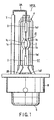
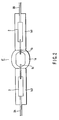
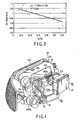
- FIGS. 1 and 2 show a metal halide lamp for vehicle headlights according to an embodiment of the invention. More specifically, FIG. 1 is a front view illustrating the entire lamp. FIG. 2 is an enlarged front view illustrating an essential part of the light emission tube of the halide lamp. FIG. 3 is a graph illustrating the relationship between the arc width of discharge and the ratio of the chromium (Cr) spectrum to the scandium (Sc) spectrum included in the lighting spectra of a metal halide lamp.
- a high-pressure discharge lamp HPDL comprises a light emission tube IT, insulation tube T, outer tube OT and a metal cap B.
- the light emission tube IT includes an airtight container 1, a pair of electrodes 1b, a pair of sealed metal leaves 2, a pair of external lead wires 3A and 3B and a discharge medium.
- the airtight container 1 includes a closing section 1a and a pair of sealing sections 1a1.
- the closing section 1a is a hollow member of a spindle shape.
- the closing section 1a has its opposite ends provided with the slim sealing sections 1a1 formed integrally therewith as one body, and has a slim and substantially cylindrical discharge space 1c.
- the internal volume of the discharge space 1c is 0.1 cc or less.
- the proximal ends of the electrodes 1b are welded, by a laser, to respective ends of the sealed metal leaves 2, described later, buried in the respective sealing sections 1a1.
- the intermediate portions of the electrodes 1b are buried in the respective sealing sections 1a1, loosely supported at predetermined positions.
- the distal ends of the metal leaves 2 project into the discharge space 1c, opposing each other from the opposite ends of the space.
- the sealed metal leaves 2 are molybdenum (Mo) leaves airtightly buried in the respective sealing sections 1 a 1 of the airtight container 1.
- the external lead wires (current guiding members) 3A and 3B have their distal ends welded to the other ends of the sealed metal leaves 2 in the sealing sections 1a1 of the airtight container 1, and have their proximal ends lead to the outside of the respective sealing sections 1a1.
- the current guiding member 3B lead to the right in FIG. 2 from the discharge (light emission) tube IT, has its intermediate portion folded along the outer tube OT, described later.
- the member 3B is then guided into a metal cap B, described later, and connected to one metal cap terminal 5.
- the current guiding member 3A lead to the left in FIG. 2 from the discharge tube IT along the axis of the container, is extended along the axis, guided into the metal cap B and connected to the other metal cap terminal (not shown).
- the closing section 1a of the airtight container 1 seals therein a discharge medium formed of first and second halides and a rare gas.
- the first halide comprises a scandium (Sc) halide and sodium (Na) halide.
- the second halide comprises at least an indium (In) halide and/or zinc (Zn) halide.
- the closing section 1a and a pair of sealing tubes connected to the opposite ends of the section 1a are formed integral as one body.
- electrode mounts each including the corresponding electrode 1b, to-be-sealed metal leaf 2 and external lead wire 3A (or 3B) formed integral with each other as one body by welding are prepared.
- one of the sealing tubes of the airtight container 1 is directed upward, and one of the electrode mounts is inserted into the sealing tube to a predetermined position.
- the sealing tube is softened by heating from the outside, and sealed by, for example, reduced-pressure sealing.
- the to-be-sealed metal leaf 2 of one of the electrode mounts is airtightly buried in the sealing section 1a1 formed by crushing the sealing tube, the electrode 1b is sealed at a predetermined position, and the external lead wire 3A is guided to the outside of the sealing section 1a1.
- the airtight container 1 is turned upside down in the atmosphere of a rare gas to direct the other sealing tube upward, and the first and second halides are sealed in the container 1 from the other sealing tube, and the other electrode mount is inserted into the other sealing tube.
- the other sealing tube is heated, softened and sealed by, for example, reduced-pressure sealing.
- the to-be-sealed metal leaf 2 of the other electrode mount is airtightly buried in the other sealing section 1a1 formed by crushing the other sealing tube, the other electrode 1b is sealed at a predetermined position, and the external lead wire 3B is guided to the outside of the sealing section 1a1.
- the outer tube OT which contains the discharge tube IT, has an ultraviolet-ray cutting function.
- the outer tube OT has a small diameter portion 6 located at its distal end and welded to the sealing section 1a 1 by glass at the shown position. Further, the other small-diameter portion (not shown) is welded to a sealing tube 1a2 by glass.
- the outer tube OT is not airtight but communicates with the outside air.
- the insulation tube T covers the current guiding member 3B.
- the metal cap B is a standardized one as a component of a metal halide lamp for vehicle head-lights, and is constructed such that it extends coaxial with the discharge tube IT and outer tube OT, and can be mounted on and dismounted from the back surface of a vehicle headlight. Further, the metal cap B includes a support band 4 extending from the front surface thereof along the axis of the lamp and covering the proximal end of the outer tube OT.
- FIGS. 1 and 2 satisfies the following conditions:
- FIG. 3 a description will be given of search results concerning the relationship between the arc width of discharge and the intensity ratio of a chromium (Cr) spectrum of 428.9 nm to a scandium (Sc) spectrum of 393.4nm included in the lighting spectra.
- the abscissa indicates the intensity ratio (Cr/Sc) of the chromium (Cr) spectrum to the scandium (Sc) spectrum included in the lighting spectra.
- the ordinate indicates the arc width (mm).
- mark ⁇ indicates measured data acquired from a number of samples, and the solid line is acquired from the measured data.
- an apparent correlation can be detected between the intensity ratio of the chromium (Cr) spectrum to the scandium (Sc) spectrum and the discharge arc width. If Cr/Sc is 0.21 or less, the discharge arc width sufficiently satisfies the standard.
- FIGS. 4 and 5 show a vehicle headlight to which the lighting device of the invention is applied.
- FIG. 4 is a perspective view of the headlight, taken from the back.
- FIG. 5 is a circuit diagram illustrating the lighting circuit of the lighting device.
- the vehicle headlight HL comprises a vehicle headlight main unit 21, two metal halide lamps HPDL and two lighting circuits OC.
- the vehicle headlight main unit 21 comprises a front surface transmission panel 21 a, reflectors 21 b and 21 c, lamp sockets 21d and attachment sections 21e, etc.
- the front surface lens 21a has a shape that accords with the corresponding outer surface portion of a vehicle, and includes predetermined optical means, such as a prism.
- the reflectors 21b and 21c are provided on the respective metal halide lamps HPDL to provide respective required light distribution characteristics.
- the lamp sockets 21d are connected to the respective output terminals of the lighting circuits OC, and provided in the respective metal caps B of the metal halide lamps HPDL.
- the attachment sections 21e are means for attaching the vehicle headlight main unit 21 to a predetermined position on a vehicle.
- the metal halide lamp HPDL has the structure as shown in FIG. 1.
- the lamp sockets 21d are connected to the vehicle headlight main unit 21, fitted in the respective metal caps.
- the two metal halide lamps HPDL are mounted on the main unit 21, providing a four-lamp-type vehicle headlight structure.
- the respective light emission sections of the metal halide lamps HPDL are substantially located at the focal points of the reflectors 21b and 21c.
- the two lighting circuits OC have a circuit structure described later. They are housed in respective metal containers 22 and used to light the respective metal halide lamps HPDL.
- each lighting circuit OC comprises a direct-current power supply 11, chopper 12, control means 13, lamp current detection means 14, lamp voltage detection means 15, igniter 16, metal halide lamp HPDL and full bridge inverter 17.
- the lighting circuits OC firstly supply a direct current and then an alternating current.
- the direct-current power supply 11 is means for supplying a direct current to the chopper 12, described later, and is formed of a battery or rectified-direct-current power supply.
- a battery is generally used as the power supply 11.
- a rectified-direct-current power supply for rectifying an alternating current may be used.
- an electrolytic condenser 11a is connected in parallel with the power supply 11 to perform smoothing.
- the chopper 12 is a DC-DC converter circuit for converting a direct-current voltage into a preset direct-current voltage, and used to adjust the voltage at the metal halide lamp HPDL to a preset value via the full bridge inverter 17, described later. If the direct-current power supply voltage is low, a step-up chopper is used, while if it is high, a step-down chopper is used.
- the control means 13 controls the chopper 12. Immediately after turn-on of the lamp, for example, the control means 13 supplies the metal halide lamp HPDL with a lamp current three times or more the rated lamp current, using the chopper 12 via the full bridge inverter 17. With lapse of time, the control means 13 gradually reduces the lamp current to the rated lamp current. Further, the control means 13 generates a constant power control signal to control the chopper 22 using a constant power, when detection signals corresponding to the lamp current and lamp voltage are fed back thereto.
- the control means 13 contains a microcomputer prestoring a temporal control pattern, which enables the above-mentioned control of supplying the metal halide lamp HPDL with the lamp current three times or more the rated lamp current, and gradually reducing the lamp current to the rated lamp current with time.
- the lamp current detection means 14 is connected in series to the metal halide lamp HPDL via the full bridge inverter 17, and used to detect a current corresponding to the lamp current and input it to the control means 13.
- the lamp voltage detection means 15 is connected in parallel to the metal halide lamp HPDL via the full bridge inverter 17, and used to detect a voltage corresponding to the lamp voltage and input it to the control means 13.
- the igniter 16 is interposed between the full bridge inverter 17 and metal halide lamp HPDL and disposed to supply the metal halide lamp HPDL with a start pulse voltage of about 20kV at the start of lighting.
- the full bridge inverter 17 comprises a bridge circuit 17a formed of four MOSFETs Q1, Q2, Q3 and Q4, a gate drive circuit 17b for alternately switching the MOSFETs Q1, Q2, Q3 and Q4, and a polarity inverting circuit 17c.
- the full bridge inverter 17 converts a fixed polarity voltage from the chopper 12 into a low-frequency alternating polarity voltage of a rectangular waveform by utilizing the alternate switching, and applies it to the metal halide lamp HPDL to light it (low-frequency alternating-current lighting).
- the MOSFETs Q1 and Q3, for example, of the bridge circuit 17a are kept on, and the MOSFETs Q2 and Q4 are kept off.
- the lighting circuits OC constructed as above, firstly a direct current and then a low-frequency alternating current are supplied to the metal halide lamps HPDL, with the result that the lamps emit a predetermined luminous flux upon turn-on. Specifically, 25% of the rated flux is realized one second after ignition, which is required as a vehicle headlight, and 80% is realized four seconds after.
Landscapes
- Engineering & Computer Science (AREA)
- Manufacturing & Machinery (AREA)
- Discharge Lamp (AREA)
- Vessels And Coating Films For Discharge Lamps (AREA)
- Discharge Lamps And Accessories Thereof (AREA)
Claims (7)
- Lampe aux halogénures métalliques comprenant :une enveloppe réfractaire, transmettant la lumière et étanche à l'air (1a) définissant à l'intérieur un espace de décharge ayant un volume interne ne dépassant pas 0,1 cm3;une paire d' électrodes. (1b) scellées dans l'enveloppe étanche, en face l'une de l'autre avec une distance entre elles ne dépassant pas 5 mm ; etun agent de décharge enfermé de façon hermétique dans l'enveloppe étanche et comprenant un matériau de type halogénure métallique et un gaz rare, le matériau de type halogénure métallique incluant un premier matériau à halogénures et un second matériau à halogénures, le premier matériau à halogénures contenant un halogénure de scandium (Sc) et un halogénure de sodium (Na), le second matériau à halogénures en contenant au moins un choisi parmi le groupe constitué d'un halogénure d'indium (In) et d'un halogénure de zinc (Zn), l'agent de décharge contenant moins de 2 mg/cm2 de mercure, et une charge sur une paroi de l'enveloppe étanche dans un état stable étant supérieure ou égale à 50 W/cm2; caractérisée parA/B ≤ 0,21, où A représente l'intensité d'un spectre de chrome (Cr) d'impureté de 428,9 nm dans le spectre lumineux, et B représente l'intensité d'un spectre de scandium (Sc) de 393,4 nm dans le spectre lumineux.
- Dispositif d'éclairage caractérisé en ce qu'il comprend :une unité principale (21) de dispositif d'éclairage ;la lampe aux halogénures métalliques (HPDL) de la revendication 1, la lampe aux halogénures métalliques étant incorporée dans l'unité principale de dispositif d'éclairage ; etun dispositif d'éclairage (OC) configuré pour allumer la lampe aux halogénures métalliques.
- Procédé de fabrication d'une lampe aux halogénures métalliques, la lampe aux halogénures métalliques comprenant une enveloppe réfractaire, transmettant la lumière et étanche à l'air (1a) définissant à l'intérieur un espace de décharge ayant un volume interne ne dépassant pas 0,1 cm3, une paire d'électrodes (1b) scellées dans l'enveloppe étanche, en face l'une de l'autre avec une distance entre elles ne dépassant pas 5 mm, et un agent de décharge enfermé de façon hermétique dans l'enveloppe étanche et comprenant un matériau de type halogénure métallique et un gaz rare, le matériau de type halogénure métallique incluant un premier matériau à halogénures et un second matériau à halogénures, le premier matériau à halogénures contenant un halogénure de scandium (Sc) et un halogénure de sodium (Na), le second matériau à halogénures en contenant au moins un choisi parmi le groupe constitué d'un halogénure d'indium (In) et d'un halogénure de zinc (Zn), l'agent de décharge contenant moins de 2 mg/cm2 de mercure, le procédé étant caractérisé en ce qu'il comprend le fait d'empêcher les composants de support d'électrode d'être touchés par un métal contenant Cr, les composants de support d'électrode incluant la paire d'électrodes, une feuille de Mo et des soudures.
- Procédé selon la revendication 3, caractérisé en ce qu'il comprend en outre la formation, à partir d'un matériau exempt de-Cr, d'une paroi intérieure d'un four utilisé dans un processus de chauffage des supports d'électrode.
- Procédé selon la revendication 3, caractérisé en ce qu'il comprend en outre le fait d'empêcher les composants de support d'électrode d'être touchés par un métal contenant du Cr dans un processus de fabrication des composants de support d'électrode.
- Procédé selon la revendication 3, caractérisé en ce qu'il comprend en outre le fait d'empêcher du quartz d'ampoule d'être touché par un métal contenant du Cr dans un processus de moulage de l'enveloppe étanche.
- Procédé selon la revendication 3, caractérisé en ce qu'il comprend en outre le fait d'empêcher l'agent de décharge d'être touché par un métal contenant du Cr dans un récipient destiné à contenir l'agent de décharge et dans un chargeur servant à charger l'agent de décharge.
Applications Claiming Priority (2)
| Application Number | Priority Date | Filing Date | Title |
|---|---|---|---|
| JP2003358935A JP2005123112A (ja) | 2003-10-20 | 2003-10-20 | メタルハライドランプおよび照明装置 |
| JP2003358935 | 2003-10-20 |
Publications (2)
| Publication Number | Publication Date |
|---|---|
| EP1526564A1 EP1526564A1 (fr) | 2005-04-27 |
| EP1526564B1 true EP1526564B1 (fr) | 2006-07-05 |
Family
ID=34386452
Family Applications (1)
| Application Number | Title | Priority Date | Filing Date |
|---|---|---|---|
| EP04256942A Expired - Fee Related EP1526564B1 (fr) | 2003-10-20 | 2004-10-20 | Lampe aux halogénures de scandium et sodium, et procédé de fabrication |
Country Status (4)
| Country | Link |
|---|---|
| US (1) | US7233110B2 (fr) |
| EP (1) | EP1526564B1 (fr) |
| JP (1) | JP2005123112A (fr) |
| DE (1) | DE602004001433T2 (fr) |
Cited By (1)
| Publication number | Priority date | Publication date | Assignee | Title |
|---|---|---|---|---|
| US8436539B2 (en) | 2007-09-24 | 2013-05-07 | Koninklijke Philips Electronics N.V. | Thorium-free discharge lamp with reduced halides and increased relative amount of Sc |
Families Citing this family (10)
| Publication number | Priority date | Publication date | Assignee | Title |
|---|---|---|---|---|
| JP2006318730A (ja) * | 2005-05-12 | 2006-11-24 | Harison Toshiba Lighting Corp | メタルハライド放電ランプおよびメタルハライド放電ランプシステム |
| JP2008098045A (ja) * | 2006-10-13 | 2008-04-24 | Harison Toshiba Lighting Corp | 自動車用メタルハライドランプ |
| WO2008056469A1 (fr) * | 2006-11-09 | 2008-05-15 | Harison Toshiba Lighting Corp. | Lampe à halogénure métallisé |
| JP2008262855A (ja) * | 2007-04-13 | 2008-10-30 | Harison Toshiba Lighting Corp | 自動車前照灯用メタルハライドランプ |
| JP5313710B2 (ja) * | 2008-02-12 | 2013-10-09 | 株式会社小糸製作所 | 放電ランプ装置用水銀フリーアークチューブ |
| JP2009289518A (ja) * | 2008-05-28 | 2009-12-10 | Koito Mfg Co Ltd | 自動車用水銀フリー放電バルブ |
| JP5242433B2 (ja) * | 2009-01-29 | 2013-07-24 | 株式会社小糸製作所 | 放電ランプ装置用水銀フリーアークチューブ |
| JP5428957B2 (ja) * | 2009-05-13 | 2014-02-26 | 東芝ライテック株式会社 | 車両用放電ランプ、および車両用放電ランプ装置 |
| WO2011042830A2 (fr) | 2009-10-09 | 2011-04-14 | Koninklijke Philips Electronics N.V. | Ensemble d'éclairage à efficacité élevée |
| JP2011222489A (ja) * | 2010-03-26 | 2011-11-04 | Panasonic Corp | 放電ランプユニット及びそれを用いた投射型画像表示装置 |
Family Cites Families (4)
| Publication number | Priority date | Publication date | Assignee | Title |
|---|---|---|---|---|
| JPH11238488A (ja) * | 1997-06-06 | 1999-08-31 | Toshiba Lighting & Technology Corp | メタルハライド放電ランプ、メタルハライド放電ランプ点灯装置および照明装置 |
| EP1150337A1 (fr) * | 2000-04-28 | 2001-10-31 | Toshiba Lighting & Technology Corporation | Lampe à décharge aux halogénures métalliques sans mercure et système d'éclairage de véhicules utilisant une telle lampe |
| EP1154455A3 (fr) | 2000-05-09 | 2003-12-03 | Matsushita Electric Industrial Co., Ltd. | Appareil et procedé pour le nettoyage d'un tube translucide pour une lampe à décharge, et lampe à décharge |
| JP2003242933A (ja) | 2002-02-15 | 2003-08-29 | Toshiba Lighting & Technology Corp | メタルハライドランプおよび自動車用前照灯装置 |
-
2003
- 2003-10-20 JP JP2003358935A patent/JP2005123112A/ja not_active Withdrawn
-
2004
- 2004-10-12 US US10/963,215 patent/US7233110B2/en not_active Expired - Fee Related
- 2004-10-20 DE DE602004001433T patent/DE602004001433T2/de not_active Expired - Fee Related
- 2004-10-20 EP EP04256942A patent/EP1526564B1/fr not_active Expired - Fee Related
Cited By (1)
| Publication number | Priority date | Publication date | Assignee | Title |
|---|---|---|---|---|
| US8436539B2 (en) | 2007-09-24 | 2013-05-07 | Koninklijke Philips Electronics N.V. | Thorium-free discharge lamp with reduced halides and increased relative amount of Sc |
Also Published As
| Publication number | Publication date |
|---|---|
| US7233110B2 (en) | 2007-06-19 |
| DE602004001433D1 (de) | 2006-08-17 |
| US20050082987A1 (en) | 2005-04-21 |
| DE602004001433T2 (de) | 2007-02-08 |
| EP1526564A1 (fr) | 2005-04-27 |
| JP2005123112A (ja) | 2005-05-12 |
Similar Documents
| Publication | Publication Date | Title |
|---|---|---|
| US7352132B2 (en) | Metal halide lamp and metal halide lamp lighting device with improved emission power maintenance ratio | |
| EP1526564B1 (fr) | Lampe aux halogénures de scandium et sodium, et procédé de fabrication | |
| EP1883278A1 (fr) | Lampe a decharge halogene metallique et dispositif d eclairage correspondant | |
| EP1432011B1 (fr) | Lampe a decharge a haute pression, dispositif de fonctionnement d'une lampe a decharge a haute pression, et dispositif de phare avant pour automobiles | |
| US6879101B2 (en) | Metal halide lamp with electrodes having a curved surface part and automotive headlamp apparatus | |
| EP1763068A1 (fr) | Lampe halogène métallique, dispositif d'éclairage pour lampe halogène métallique et phare | |
| JP4401762B2 (ja) | メタルハライドランプおよび照明装置 | |
| US6670765B2 (en) | Mercury-free metal halide lamp, with contents and electric power control depending on resistance properties | |
| EP1763067A1 (fr) | Lampe halogène métallique, dispositif d'éclairage pour lampe halogène métallique et phare | |
| US20050099129A1 (en) | Metal halide lamp used for both of vehicle headlight and infrared night imaging vision equipment, and metal halide lamp lighting apparatus | |
| EP1912249B1 (fr) | Lampe halogene, dispositif d' eclairage a lampe halogene et phare | |
| JP4208222B2 (ja) | 前照灯用短アーク形メタルハライドランプ、メタルハライドランプ点灯装置および前照灯 | |
| JP2004220880A (ja) | 高圧放電ランプおよび車両用ヘッドライト | |
| JP2005032448A (ja) | メタルハライドランプおよび照明装置 | |
| JP4443868B2 (ja) | メタルハライドランプおよび照明装置 | |
| JP2004253362A (ja) | 高圧放電ランプおよび照明装置 | |
| JP2004220879A (ja) | 自動車前照灯用メタルハライドランプおよび自動車用前照灯装置 | |
| JP2005093354A (ja) | メタルハライドランプおよび照明装置 | |
| JP2005100852A (ja) | メタルハライドランプおよび照明装置 | |
| JP2005093355A (ja) | 2重管形ランプおよび照明装置 | |
| JP2005019297A (ja) | 高圧放電ランプおよび照明装置 | |
| JP2005100743A (ja) | メタルハライドランプおよび照明装置 | |
| JP2004206980A (ja) | メタルハライドランプおよび自動車用前照灯装置 | |
| KR20070031929A (ko) | 메탈 핼라이드 램프, 메탈 핼라이드 램프 점등장치 및전조등 | |
| JP2005093356A (ja) | メタルハライドランプおよび照明装置 |
Legal Events
| Date | Code | Title | Description |
|---|---|---|---|
| PUAI | Public reference made under article 153(3) epc to a published international application that has entered the european phase |
Free format text: ORIGINAL CODE: 0009012 |
|
| 17P | Request for examination filed |
Effective date: 20041118 |
|
| AK | Designated contracting states |
Kind code of ref document: A1 Designated state(s): AT BE BG CH CY CZ DE DK EE ES FI FR GB GR HU IE IT LI LU MC NL PL PT RO SE SI SK TR |
|
| AX | Request for extension of the european patent |
Extension state: AL HR LT LV MK |
|
| GRAP | Despatch of communication of intention to grant a patent |
Free format text: ORIGINAL CODE: EPIDOSNIGR1 |
|
| AKX | Designation fees paid |
Designated state(s): DE FR GB |
|
| RIN1 | Information on inventor provided before grant (corrected) |
Inventor name: KAWASHIMA, HIROMICHI Inventor name: UEMURA, KOZO |
|
| GRAS | Grant fee paid |
Free format text: ORIGINAL CODE: EPIDOSNIGR3 |
|
| GRAA | (expected) grant |
Free format text: ORIGINAL CODE: 0009210 |
|
| AK | Designated contracting states |
Kind code of ref document: B1 Designated state(s): DE FR GB |
|
| REG | Reference to a national code |
Ref country code: GB Ref legal event code: FG4D |
|
| REF | Corresponds to: |
Ref document number: 602004001433 Country of ref document: DE Date of ref document: 20060817 Kind code of ref document: P |
|
| ET | Fr: translation filed | ||
| PLBE | No opposition filed within time limit |
Free format text: ORIGINAL CODE: 0009261 |
|
| STAA | Information on the status of an ep patent application or granted ep patent |
Free format text: STATUS: NO OPPOSITION FILED WITHIN TIME LIMIT |
|
| 26N | No opposition filed |
Effective date: 20070410 |
|
| PGFP | Annual fee paid to national office [announced via postgrant information from national office to epo] |
Ref country code: FR Payment date: 20070912 Year of fee payment: 4 |
|
| PGFP | Annual fee paid to national office [announced via postgrant information from national office to epo] |
Ref country code: DE Payment date: 20071203 Year of fee payment: 4 |
|
| GBPC | Gb: european patent ceased through non-payment of renewal fee |
Effective date: 20081020 |
|
| REG | Reference to a national code |
Ref country code: FR Ref legal event code: ST Effective date: 20090630 |
|
| PG25 | Lapsed in a contracting state [announced via postgrant information from national office to epo] |
Ref country code: DE Free format text: LAPSE BECAUSE OF NON-PAYMENT OF DUE FEES Effective date: 20090501 |
|
| PG25 | Lapsed in a contracting state [announced via postgrant information from national office to epo] |
Ref country code: FR Free format text: LAPSE BECAUSE OF NON-PAYMENT OF DUE FEES Effective date: 20081031 |
|
| PG25 | Lapsed in a contracting state [announced via postgrant information from national office to epo] |
Ref country code: GB Free format text: LAPSE BECAUSE OF NON-PAYMENT OF DUE FEES Effective date: 20081020 |