EP1526368A1 - Verfahren und vorrichtung zur polarizations-moden-disprsion-messung einer optischen faser - Google Patents
Verfahren und vorrichtung zur polarizations-moden-disprsion-messung einer optischen faser Download PDFInfo
- Publication number
- EP1526368A1 EP1526368A1 EP03765330A EP03765330A EP1526368A1 EP 1526368 A1 EP1526368 A1 EP 1526368A1 EP 03765330 A EP03765330 A EP 03765330A EP 03765330 A EP03765330 A EP 03765330A EP 1526368 A1 EP1526368 A1 EP 1526368A1
- Authority
- EP
- European Patent Office
- Prior art keywords
- optical fiber
- light
- mode dispersion
- polarization mode
- fluctuation
- Prior art date
- Legal status (The legal status is an assumption and is not a legal conclusion. Google has not performed a legal analysis and makes no representation as to the accuracy of the status listed.)
- Withdrawn
Links
- 239000013307 optical fiber Substances 0.000 title claims abstract description 176
- 230000010287 polarization Effects 0.000 title claims abstract description 148
- 239000006185 dispersion Substances 0.000 title claims abstract description 112
- 238000005259 measurement Methods 0.000 title description 24
- 238000000691 measurement method Methods 0.000 title description 4
- 238000000034 method Methods 0.000 claims abstract description 65
- 230000003287 optical effect Effects 0.000 claims description 26
- 239000000835 fiber Substances 0.000 claims description 6
- 238000000253 optical time-domain reflectometry Methods 0.000 claims 2
- 239000011159 matrix material Substances 0.000 description 15
- 230000000694 effects Effects 0.000 description 11
- 230000000644 propagated effect Effects 0.000 description 7
- 230000005540 biological transmission Effects 0.000 description 5
- 238000012935 Averaging Methods 0.000 description 3
- 238000004891 communication Methods 0.000 description 3
- 238000007689 inspection Methods 0.000 description 2
- 238000004519 manufacturing process Methods 0.000 description 2
- 239000004065 semiconductor Substances 0.000 description 2
- 230000003321 amplification Effects 0.000 description 1
- 230000002238 attenuated effect Effects 0.000 description 1
- 230000015572 biosynthetic process Effects 0.000 description 1
- 238000004364 calculation method Methods 0.000 description 1
- 230000001186 cumulative effect Effects 0.000 description 1
- 230000002950 deficient Effects 0.000 description 1
- 230000006866 deterioration Effects 0.000 description 1
- 238000005516 engineering process Methods 0.000 description 1
- 230000005284 excitation Effects 0.000 description 1
- 230000006355 external stress Effects 0.000 description 1
- 238000003780 insertion Methods 0.000 description 1
- 230000037431 insertion Effects 0.000 description 1
- 238000012417 linear regression Methods 0.000 description 1
- 230000007774 longterm Effects 0.000 description 1
- 239000000463 material Substances 0.000 description 1
- 238000003199 nucleic acid amplification method Methods 0.000 description 1
- 230000010355 oscillation Effects 0.000 description 1
- 238000011160 research Methods 0.000 description 1
- 238000007619 statistical method Methods 0.000 description 1
- 238000012360 testing method Methods 0.000 description 1
Images


Classifications
-
- G—PHYSICS
- G01—MEASURING; TESTING
- G01M—TESTING STATIC OR DYNAMIC BALANCE OF MACHINES OR STRUCTURES; TESTING OF STRUCTURES OR APPARATUS, NOT OTHERWISE PROVIDED FOR
- G01M11/00—Testing of optical apparatus; Testing structures by optical methods not otherwise provided for
- G01M11/30—Testing of optical devices, constituted by fibre optics or optical waveguides
- G01M11/31—Testing of optical devices, constituted by fibre optics or optical waveguides with a light emitter and a light receiver being disposed at the same side of a fibre or waveguide end-face, e.g. reflectometers
- G01M11/3181—Reflectometers dealing with polarisation
Definitions
- the present invention relates to a method of measuring polarization mode dispersion of an optical fiber having a comparatively small birefringence that is used in a fiber-optic communication system, and to a measuring apparatus for the same.
- Polarization mode dispersion is an important consideration when dealing with an optical fiber used in a fiber-optic communication system and it can be generated by concentricity error or the non-circularity of the core of an optical fiber, or by external stress or the like.
- Polarization mode dispersion is a group delay difference between two orthogonal polarization modes of propagated light along an optical fiber. The larger the polarization mode dispersion of an optical fiber, the more the pulse width is spread by this group delay difference. Therefore, polarization mode dispersion is one factor preventing high-speed transmission.
- the planner or constructor should comprehend or measure values of the PMD of the optical fibers used in the system.
- An interferometric method and a Jones Matrix Eigenanalysis method and the like are well-known measuring methods for the PMD of an optical fiber.
- the present invention was conceived in view of the above circumstances and it is an object thereof to provide an optical fiber polarization mode dispersion measuring method and measuring apparatus that enable the longitudinal distribution of a polarization mode dispersion of an optical fiber to be obtained easily using a simple apparatus.
- a method of measuring polarization mode dispersion in an optical fiber includes inputting linearly polarized pulse light into the optical fiber, separating the input linearly polarized light from backscattered light from the optical fiber, detecting a light intensity of the backscattered light as time series data since the generation of the pulse light, calculating a fluctuation of the detected light intensity, and evaluating polarization mode dispersion in the optical fiber, based on the calculated fluctuation value.
- the plane of polarization of the input linearly polarized light may be the same as the plane of polarization of the backscattered light from the optical fiber.
- a first fluctuation of light intensity can be calculated by inputting linearly polarized pulse light into a first end of the optical fiber and detecting time series data of the light intensity of the backscattered light through the first end of the fiber.
- a second fluctuation of light intensity can be calculated by inputting linearly polarized pulse light into a second end of the optical fiber and detecting time series data of the light intensity of the backscattered light through the second end of the fiber.
- the polarization mode dispersion in the optical fiber can be evaluated based on an average value of the first fluctuation of light intensity and the second fluctuation of light intensity.
- the polarization mode dispersion of a predetermined section of the optical fiber can be evaluated by comparing the fluctuation of the light intensity measured in the predetermined section of the optical fiber with the fluctuation of the light intensity measured using the same method in an optical fiber whose polarization mode dispersion is already known.
- a longitudinal distribution of polarization mode dispersion in an optical fiber can be evaluated by comparing the fluctuation of the optical intensity measured in each of a plurality of sections in the longitudinal direction of the optical fiber with fluctuation of the light intensity measured using the same method in an optical fiber whose polarization mode dispersion is already known.
- the fluctuation of the light intensity can be calculated as fluctuation in a regression residual error using the least-square method.
- the scale of the fluctuation of the light intensity can be standard deviation or a difference between a maximum intensity and a minimum intensity in predetermined section.
- An apparatus for carrying out the above described method, according to a second exemplary aspect of the present invention includes a pulse generating device, an optical circulator that inputs pulse light generated by the pulse light generating device into an end of the optical fiber, and outputs backscattered light that has returned through the end of the optical fiber, a photodetector that detects a light intensity of the backscattered light output from the optical circulator as time series since the generation of the pulse light, an analyzer that analyzes polarization mode dispersion in an optical fiber based on the light intensity of the backscattered light output from the photo detector, and at least one polarizer that linearly polarizes incident light input into the optical fiber and backscattered light output from the optical fiber.
- the at least one polarizer can polarize the incident light input into the optical fiber and the output light output form the optical fiber into linearly into linearly polarized light of the same plane of polarization.
- the polarizer can be a polarization-beam-combiner-type coupler.
- the apparatus for measuring polarization mode dispersion in an optical fiber can include a OTDR apparatus, and a polarizer that polarizes both incident light input into the optical fiber and output light from the optical fiber into linear polarized light of the same plane of polarization. Further, an optical amplifier apparatus can be provided between the commercialized OTDR apparatus and the polarizer.
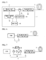
- FIG. 1 shows a measuring apparatus used in a method of measuring the polarization mode dispersion of an optical fiber 2, according to a first exemplary embodiment of the present invention.
- the measuring apparatus 1 is provided with a timing control device 10, a pulse light generating device 11, first and second polarizers 12a and 12b, an optical circulator 13, a photodetector 14, and an analyzer 15.
- the timing control device 10 outputs timing signals that correspond to the output timing of pulse light to each of the pulse light generating device 11, the photodetector 14, and the analyzer 15. Timing signals are pulse signals having a predetermined duration.
- the pulse light generating device 11 emits continuous light of a wavelength of several kHz, and emits light pulses of a predetermined wavelength using as a trigger timing signals input from the timing control device 10. By controlling the duration of the timing signals, the width of the light pulses can be appropriately controlled.
- a semiconductor laser fitted with an external resonator, a semiconductor laser excitation solid-state laser, or the like, for example, may be used as the pulse light generating device 11.
- the first and second polarizers 12a and 12b linearly polarize incident pulse light and backscattered light, respectively.
- the polarizers 12a and 12b may be set such that the optional plane of polarization of the linear polarized light input into the optical fiber 2 and the linear polarized light output from the optical fiber 2 are not the same. However, it is desirable, though not necessary, that the polarizers 12a and 12b are adjusted such that the plane of polarization of the linear polarized light input into the optical fiber 2 and that of the linear polarized light output from the optical fiber 2 are the same. Rarely, the light intensity of linearly polarized light separated by the polarizer is so small that it cannot be measured.
- polarization splitting devices 12a and 12b by adjusting the polarization splitting devices 12a and 12b beforehand such that they set an identical plane of polarization for both the linear polarized light input into the optical fiber and the linear polarized light output from the optical fiber in same plane of polarization, it is possible to adjust the polarizers 12a and 12b when adjusting the axial direction of the optical fiber and the angle of the plane of polarization such that measurement becomes possible.
- Bulk-type polarizers and the like can be used as the polarizers 12a and 12b.
- polarization-beam-combiner-type couplers are preferable, though not necessary, from the standpoints of dynamic range and long-term reliability because they have low insertion loss and high reliability.
- the polarization-beam-combiner-type coupler described in Japanese Unexamined Patent Application, First Publication No. 2001-51150, for example, can be used.
- the optical circulator 13 is an optical component that inputs light that has been incident from the pulse light generating device 11 into the optical fiber 2, and that also outputs backscattered light from the optical fiber 2 being measured into the photodetector 14.
- a circulator, beam splitter, directional coupler, or the like can be used as the optical circulator 13.
- the photodetector 14 ascertains the times when pulse light is generated based on control signals sent from the timing control device 10, and measures, in time domains, the light intensity of backscattered light that has been polarized by the second polarizer 12b as a time series from the times of pulse light generation.
- a photodetector such as an A/D converter can be used for the photodetector 14.
- the analyzer 15 is a device that analyzes the longitudinal distribution of polarization mode dispersion of the optical fiber 2, using the method described below, based on fluctuation of the light intensity in the time series data detected by the photodetector 14.
- a computer that is able to perform statistical analysis on the time series data expressed by a relationship between the distance and light intensity in the optical fiber can be used for the analyzer 15.
- linearly polarized pulse light is generated. This light is then input into the optical fiber 2 via the optical circulator 13.
- the incident pulse light that has been input into the optical fiber 2 is partly scattered backwards by Rayleigh scattering as the incident light is propagated along the optical fiber 2, and backscattered light is returned to the measuring apparatus 1.
- linearly polarized light having a predetermined plane of polarization is separated from the backscattered light.
- the light intensity is detected as time series data starting from the generation of pulse light by the photodetector 14.
- time series data of the light intensity that is obtained in this way is measured on the horizontal axis taken as time elapsed since the generation of pulse light and the vertical axis taken as the light intensity.
- the time elapsed since the generation of pulse light is the time required for light to travel reciprocally between the measuring apparatus 1 and the location in the optical fiber 2 where backscattered light is generated, and corresponds to the distance between the measuring apparatus 1 and the location where the backscattered light is generated.
- time series data such as this, fluctuation is observed in the light intensity of the backscattered light.
- the state of polarization of pulse light that is propagated along the optical fiber 2 changes with the polarization mode dispersion.
- the spatial resolution of the measuring apparatus 1 is determined from the length of the pulse light generated by the pulse light generating device 11 in the optical fiber 2 and from the time resolution of the photodetector 14.
- the light intensity of backscattered light is attenuated linearly as the distance increases by attenuation of the input pulse light.
- linear regression be performed for the relationship between distance and light intensity over the entire length of the optical fiber 2 using the least-square method, and that, taking the estimated amount of this regression as the representative center value of the section, the fluctuation of the light intensity is calculated based on the regression residual error obtained by subtracting the estimated amount of the least squares from the measured value of the light intensity in the section.
- the results when the distribution of the regression residual error is calculated from the fluctuation of the light intensity in FIG. 2 are shown in FIG. 3. By converting the light intensity into regression residual error in this way, the fluctuation of the light intensity can be expressed around 0 thereof.
- Fluctuation in the regression residual error of the light intensity can be indexed and quantified in the form of a suitable scale that is in general use statistically.
- a suitable scale examples include standard deviation, the difference between maximum value and minimum value (i.e., the range), averaged deviation, and averaged difference.
- standard deviation or the range are preferable, though not necessary, because standard deviation is unbiased and calculation of the range is easy.
- the length of the section used to determine distribution of the polarization mode dispersion is preferably determined so as to correspond to the envisioned beat length of the optical fiber 2.
- the beat length is the length over which the phase difference between mutually-perpendicular X polarized light and Y polarized light becomes 2 ⁇ as the light is propagated along the optical fiber.
- the length of a section sets two to ten times the beat length, and approximately 100 meters would be suitable.
- the results of calculating fluctuation of the light intensity at intervals of 100 meters from the distribution of the regression residual error of the light intensity shown in FIG. 3 are shown in FIG. 4.
- FIG. 4 As can be understood from this drawing, by taking a section length that is sufficiently longer than the beat length, unessential conspicuous oscillations and variations are flattened, and it is possible to obtain a distribution that conforms to the distribution of the polarization mode dispersion.
- the reference optical fiber As the reference of optical fiber, an optical fiber whose material and optical characteristics are similar type to those of the optical fiber 2 should be used. Furthermore, the reference optical fiber should be one in which the fluctuation in the regression residual error of the light intensity is substantially uniform over the entire length thereof.
- the polarization splitting device 12 is placed between the optical circulator 13 and the optical fiber 2.
- the polarization splitting device 12 can be used to modify either incident pulse light or backscattered light.
- the remainder of the structure of the apparatus can be the same as the structure of the first example of the measuring apparatus 1 shown in FIG. 1. According to this measuring apparatus 1 of FIG. 5, because it is possible to reduce the number of polarization splitting devices 12 that are required to one, the cost of the measuring apparatus 1 can be lowered even further.
- a third example of a measuring apparatus 1 as shown in FIG. 6 is an apparatus that is provided with a commercialized optical time domain reflectometer (OTDR) apparatus 3 and a polarizer 12.
- the polarizer 12 is placed between the OTDR 3 and the optical fiber 2.
- OTDR 3 a timing control device 10
- pulse generating device 11 a pulse generating device 11
- optical circulator 13 a photodetector 14
- analyzer 15 an analyzer
- an optical amplifier 30 that amplifies incident pulse light is placed between the OTDR 3 and the polarizer 12 of the measuring apparatus 1 shown in FIG. 3.
- the optical amplifier 30 is formed by an optical amplifier 31, two circulators 32, and a detour transmission path 33.
- the circulation direction of the circulators 32 is such that incident pulse light is propagated on the optical amplifier 31 side and backscattered light is propagated on the detour transmission path 33 side.
- the two ends of the optical fiber 2 can be differentiated by being named respectively, for example, end a and end b.
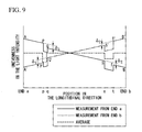
- the measuring apparatus 1 is connected to end a of the optical fiber 2 and, using the same procedure as in the first example of the measurement method described above, a first fluctuation of the light intensity is calculated by inputting linear polarized pulse light into the end a and then detecting time series data of the linear polarized light intensity.
- the measuring apparatus 1 is connected to the end b of the optical fiber 2 and, in the same way, a second fluctuation of the light intensity is calculated by inputting linear polarized pulse light into the end b and then detecting time series data of the linear polarized light intensity.
- the first fluctuation of the light intensity that was measured from the end a and the second fluctuation of the light intensity that was measured from the end b are then averaged with the positions in the longitudinal direction of the optical fiber 2 matched. Then, based on this average value, the polarization mode dispersion of the optical fiber 2 is evaluated using the same procedure as that used in the above-described first embodiment of the measurement method.
- An example of a case in which it is useful to make a measurement respectively from each end of the optical fiber 2 in this way is one in which the optical fiber 2 is comparatively long.
- the detected backscattered light becomes depolarized. Therefore, coherency in this pulse light is reduced and, as is shown in typical view in FIG. 8, fluctuation of the light intensity that returns to the measuring apparatus 1 is sometimes less than a size that reflects the actual polarization mode dispersion of the optical fiber 2.
- the accumulated polarization mode dispersion from the incident end is determined by the distance from the incident end.
- the distance from the incident end the greater the effects of the accumulated polarization mode dispersion and the smaller the fluctuation of the light intensity. Therefore, superficially, at a position that is at a distance from the incident end, the apparent polarization mode dispersion is observed as being worse than the actual polarization mode dispersion if the optical fiber is measured by the method of the first embodiment of the method of measuring polarization mode dispersion of the present invention.
- This type of apparent increase of polarization mode dispersion is more conspicuous the greater the distance between the point being observed and the measuring apparatus 1. For example, if the length of the optical fiber 2 is 15 km or more, this effect cannot be ignored.
- Accumulated PMD between the point being observed and the measuring apparatus 1 affect the reduction in the coherency of the pulse light. For example, if there is a section along the optical fiber 2 in which the polarization mode dispersion is remarkably bad, then for polarization mode dispersion at a position beyond that section (i.e. the position farther from the PMD bad section from incident end), backscattered light from that position has to pass through the section where the polarization mode dispersion is remarkably bad. That is, if there is a section between the point and the measuring apparatus 1 where the polarization mode dispersion is particularly bad, when observed it appears to be worse than the real value.
- a difference in level ⁇ 1 is generated between the line AP and the line QS by the effects of the section pq
- a difference in level ⁇ 2 is generated between the line QS and the line TB by the effects of the section st.
- fluctuation of the light intensity is lowered by the amount ⁇ 1 in the section qs
- in the section tb is further lowered by the amount ⁇ 1 + ⁇ 2. Therefore, in a measurement from the one end side only, the polarization mode dispersion in the section on the further side from the measuring apparatus appears upon observation to be worse than the actual polarization mode dispersion.
- the measuring apparatus 1 is connected to the end b side, and fluctuation of the light intensity is measured by inputting pulse light from the end b, in a waveform A'P'Q'S'T'B' of fluctuation of the light intensity, a difference in level ⁇ 2 is generated between the line T'B' and the line Q'S' by the effects of the section st, and a difference in level ⁇ 1 is generated between the line Q'S' and the line A'P' by the effects of the section pq.
- fluctuation of the light intensity is lowered by the amount ⁇ 2 in the section qs, and in the section ap is further lowered by the amount ⁇ 1 + ⁇ 2.
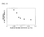
- FIG. 11 A relationship between the results of a measurement of polarization mode dispersion that are determined using Jones Matrix Eigenanalysis method and fluctuation of the light intensity measured using the measuring method of the present invention are shown in FIG. 11.
- the horizontal axis measures the polarization mode dispersion measured using Jones Matrix Eigenanalysis method, while the vertical axis measures the standard deviation of the regression residual error of the light intensity measured using the measuring method of the present invention.
- the measurements were repeated five times with intervals between each test so that average values thereof were obtained.
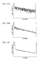
- Time series data of the light intensity for the above optical fibers 2 is shown in FIG. 12A and FIG. 12B.
- FIG. 12A shows the results obtained for all the optical fibers 2, while FIG. 12B shows the enlarged view of FIG. 12A for the four optical fibers nearest to the measuring apparatus.
- Each section of the optical fibers 2 was measured.
- An example of a relationship between the fluctuation of the light intensity and the polarization mode dispersion measured using Jones Matrix Eigenanalysis method is shown in FIG. 13.
- the symbol “ ⁇ ” shows the results for the above described optical fibers 2, while the symbol “ ⁇ ” shows the results for the conventional optical fiber shown in FIG. 9.
- the correlation between polarization mode dispersion and fluctuation of the light intensity shows the same trend as that for the results of FIG. 9. Namely, sections in which the polarization mode dispersion exceeds 0.10 ps/ km can be clearly picked out from those in which the polarization mode dispersion is less than 0.10 ps/ km .
- the longitudinal distribution of the polarization mode dispersion of the optical fiber can be measured to a sufficiently practical degree, and it is possible in one measurement to differentiate between defective sections, in which the polarization mode dispersion is comparatively large, and superior sections, in which the polarization mode dispersion is comparatively small.
- the measurable distance was approximately 30 km. Compared with when the optical amplifier apparatus 30 was not used, the distance was extended by a factor of 1.5. Moreover, the polarization mode dispersion values measured using the present invention had substantially good agreement to the polarization mode dispersion values that were measured using the Jones Matrix Eigenanalysis method.
- the optical fiber being measured had a length of approximately 35 km and the polarization mode dispersion thereof was found using the Jones Matrix Eigenanalysis method.
- the measuring apparatus shown in FIG. 6 was used as the measuring apparatus. With the optical fiber was sectionalized into 100 meter sections, fluctuation of the light intensity at respective positions in the longitudinal direction of the optical fiber was determined in the form of a standard deviation of the regression residual error of the light intensity within the range of each section.
- the straight line J shows the level of fluctuation of the light intensity that is predicted from the average value of the PMD that is measured using the Jones Matrix Eigenanalysis method for the total length of the optical fiber 2.
- the straight line H shows the average level of the fluctuation of the light intensity that is obtained from the measurement using the process of the present invention.
- the fluctuation of the light intensity distributes up and down while showing a comparatively similar pattern, in locations that are beyond the sections where the PMD is bad (for example, X1 and X2 in FIG 14) looking from the side of the measuring apparatus 1.
- the fluctuation of the light intensity is comparatively small, and the sections (the vicinity of Y for measurement from end b and the vicinity of Z for measurement from end a) appears as if they has poor PMDs.
- the vicinities of these sections Y and Z in the average values shown by the thick, broken line in FIG.
- a method of measuring polarization mode dispersion in an optical fiber that uses a measuring apparatus that includes: a pulse generating device; an optical circulator that inputs pulse light, generated by the pulse light generating device, into one end of an optical fiber, and that also outputs backscattered light that has returned to the one end of the optical fiber; a photodetector that detects a light intensity of backscattered light discharged from the optical circulator as time series since the generation of the pulse light; an analyzer that analyzes polarization mode dispersion in an optical fiber based on an output from the photo detector; and at least one polarization splitting device that changes incident light input into an optical fiber and output light output from the optical fiber into linear polarized light, the present invention has the advantage that a tunable light source, a polarization controller, a polarization analyzer, and a phase detector are not required. Further, using a simple apparatus, it is possible to measure the longitudinal distribution of the polarization mode dispersion in an optical fiber.
Landscapes
- Physics & Mathematics (AREA)
- Optics & Photonics (AREA)
- Chemical & Material Sciences (AREA)
- Analytical Chemistry (AREA)
- General Physics & Mathematics (AREA)
- Investigating Or Analysing Materials By Optical Means (AREA)
- Testing Of Optical Devices Or Fibers (AREA)
- Photometry And Measurement Of Optical Pulse Characteristics (AREA)
Applications Claiming Priority (5)
| Application Number | Priority Date | Filing Date | Title |
|---|---|---|---|
| JP2002211387 | 2002-07-19 | ||
| JP2002211387 | 2002-07-19 | ||
| JP2002261283 | 2002-09-06 | ||
| JP2002261283 | 2002-09-06 | ||
| PCT/JP2003/009175 WO2004010098A1 (ja) | 2002-07-19 | 2003-07-18 | 光ファイバの偏波モード分散の測定方法及びその測定装置 |
Publications (2)
| Publication Number | Publication Date |
|---|---|
| EP1526368A1 true EP1526368A1 (de) | 2005-04-27 |
| EP1526368A4 EP1526368A4 (de) | 2007-07-18 |
Family
ID=30772220
Family Applications (1)
| Application Number | Title | Priority Date | Filing Date |
|---|---|---|---|
| EP03765330A Withdrawn EP1526368A4 (de) | 2002-07-19 | 2003-07-18 | Verfahren und vorrichtung zur polarizations-moden-disprsion-messung einer optischen faser |
Country Status (5)
| Country | Link |
|---|---|
| US (1) | US7212281B2 (de) |
| EP (1) | EP1526368A4 (de) |
| JP (1) | JP4008470B2 (de) |
| CN (1) | CN100541158C (de) |
| WO (1) | WO2004010098A1 (de) |
Cited By (2)
| Publication number | Priority date | Publication date | Assignee | Title |
|---|---|---|---|---|
| EP1746403A1 (de) * | 2005-07-19 | 2007-01-24 | Agilent Technologies, Inc. | Optische Reflektometrieanalyse mit einer Zeitanpassung auf Teil-Ansprechsignalen |
| EP1929266A1 (de) * | 2005-08-31 | 2008-06-11 | Corning Incorporated | Verfahren zur evaluierung von faser-pmd durch verwendung von potdr-trace |
Families Citing this family (25)
| Publication number | Priority date | Publication date | Assignee | Title |
|---|---|---|---|---|
| FR2844354B1 (fr) * | 2002-09-05 | 2005-09-30 | Cit Alcatel | Procede de reflectometrie a onde optique polarisee (potdr) |
| US6946646B2 (en) * | 2002-11-05 | 2005-09-20 | Corning Incorporated | Method of evaluating fiber PMD using polarization optical time domain reflectometry |
| FR2853092A1 (fr) * | 2003-03-31 | 2004-10-01 | France Telecom | Dispositif optique, notamment de suppression du bruit dit de double retro-diffusion rayleigh, et installation comportant un tel dispositif |
| JP4781746B2 (ja) | 2005-04-14 | 2011-09-28 | 株式会社フジクラ | 光ファイバの複屈折測定方法及び測定装置及び光ファイバの偏波モード分散測定方法 |
| US7164469B1 (en) | 2005-06-30 | 2007-01-16 | Corning Incorporated | Method of evaluating fiber PMD using composite POTDR trace |
| CA2619719A1 (en) * | 2005-09-29 | 2007-04-05 | Exfo Electro-Optical Engineering Inc. | Polarization optical time domain reflectometer and method of determining pmd |
| US20100073667A1 (en) * | 2007-03-28 | 2010-03-25 | Normand Cyr | Method and Apparatus for Determining Differential Group Delay and Polarization Mode Dispersion |
| US20080100828A1 (en) * | 2005-09-29 | 2008-05-01 | Normand Cyr | Polarization-sensitive optical time domain reflectometer and method for determining PMD |
| US9829429B2 (en) | 2005-09-29 | 2017-11-28 | Exfo Inc | Determining a polarization-related characteristic of an optical link |
| JP4002934B2 (ja) * | 2005-10-03 | 2007-11-07 | 株式会社アドバンテスト | 散乱光測定装置 |
| ES2353530T3 (es) * | 2006-09-16 | 2011-03-02 | Acterna, Llc | Medición de la dispersión de modo de polarización. |
| US7999930B2 (en) * | 2008-10-07 | 2011-08-16 | Corning Incorporated | Detection system and optical fiber for use in such system |
| JP5282982B2 (ja) * | 2010-01-22 | 2013-09-04 | 清水建設株式会社 | 光ファイバセンサの計測精度の評価方法および評価装置 |
| CN101968562B (zh) * | 2010-09-30 | 2012-05-23 | 上海电信工程有限公司 | 应用偏振模色散模块的城市管道通信光缆不中断割接方法 |
| GB201019117D0 (en) * | 2010-11-11 | 2010-12-29 | Fotech Solutions Ltd | Distributed optical fibre sensor |
| RU2503939C1 (ru) * | 2012-07-17 | 2014-01-10 | Федеральное государственное образовательное бюджетное учреждение высшего профессионального образования "Поволжский государственный университет телекоммуникаций и информатики" (ФГОБУ ВПО ПГУТИ) | Способ определения места повреждения оптического волокна |
| TWI506968B (zh) * | 2012-12-27 | 2015-11-01 | Chunghwa Telecom Co Ltd | Single - ended Fiber Optic Dispersion Fast Test Device and Method |
| US9819143B2 (en) * | 2013-06-21 | 2017-11-14 | Nufern | Method and apparatus for polarization determination and/or control in optical fiber amplifying systems |
| CN103926221A (zh) * | 2014-03-26 | 2014-07-16 | 江苏中能光电技术有限公司 | 一种基于光纤传感的分布式瓦斯监测系统及监测方法 |
| CN104006948B (zh) * | 2014-06-12 | 2016-06-22 | 天津大学 | 基于多峰分裂周期解调保偏光纤偏振耦合点位置的方法 |
| CN106525390B (zh) * | 2016-11-09 | 2018-10-26 | 哈尔滨工程大学 | 一种用于具有超高分布式双折射色散的光纤保偏器件的色散补偿方法 |
| JP6922383B2 (ja) * | 2017-04-27 | 2021-08-18 | 富士通株式会社 | 光変動位置測定装置、光変調変換器および光変動位置測定方法 |
| WO2019189192A1 (ja) * | 2018-03-27 | 2019-10-03 | 日本電気株式会社 | 光ファイバセンサ及び解析方法 |
| JP7259383B2 (ja) * | 2019-02-13 | 2023-04-18 | 富士通株式会社 | 光伝送装置、光受信装置及び推定方法 |
| CN110987367B (zh) * | 2019-11-29 | 2022-06-03 | 山西大学 | 一种测量和控制纳米光纤偏振模式的装置和方法 |
Family Cites Families (11)
| Publication number | Priority date | Publication date | Assignee | Title |
|---|---|---|---|---|
| JPS62207927A (ja) | 1986-03-10 | 1987-09-12 | Yokogawa Electric Corp | 光フアイバ測定器 |
| US5384635A (en) * | 1993-08-10 | 1995-01-24 | At&T Corp. | Remote sensing in optical fiber networks by synchronously detecting backscattered optical signals |
| US5966207A (en) | 1997-08-18 | 1999-10-12 | Corning Incorporated | Methods for identifying optical fibers which exhibit elevated levels of polarization mode dispersion |
| EP1097532B1 (de) * | 1998-07-10 | 2003-12-10 | Siemens Aktiengesellschaft | Einrichtung zur detektion von polarisationsmodendispersion |
| US6342945B1 (en) * | 1999-03-31 | 2002-01-29 | Corning Incorporated | System and method for measuring polarization mode dispersion suitable for a production environment |
| JP2000329651A (ja) | 1999-05-19 | 2000-11-30 | Advantest Corp | 偏波モード分散測定装置 |
| JP2001051150A (ja) | 1999-05-31 | 2001-02-23 | Fujikura Ltd | 偏波保持光ファイバカプラの製造方法 |
| US6504604B1 (en) * | 1999-11-12 | 2003-01-07 | Lucent Technologies, Inc. | In situ polarization mode dispersion measurement |
| JP3749646B2 (ja) | 2000-02-21 | 2006-03-01 | 独立行政法人科学技術振興機構 | 偏波モード分散測定装置および偏波モード分散測定方法 |
| JP2002048680A (ja) * | 2000-08-01 | 2002-02-15 | Anritsu Corp | 光ファイバの偏波モード分散分布測定方法及び装置 |
| US6724469B2 (en) * | 2002-03-15 | 2004-04-20 | Exfo Electro-Optical Engineering Inc. | Polarization-OTDR for measuring characteristics of optical fibers |
-
2003
- 2003-07-18 CN CNB03816809XA patent/CN100541158C/zh not_active Expired - Fee Related
- 2003-07-18 JP JP2005505166A patent/JP4008470B2/ja not_active Expired - Lifetime
- 2003-07-18 US US10/521,236 patent/US7212281B2/en not_active Expired - Lifetime
- 2003-07-18 WO PCT/JP2003/009175 patent/WO2004010098A1/ja not_active Ceased
- 2003-07-18 EP EP03765330A patent/EP1526368A4/de not_active Withdrawn
Non-Patent Citations (2)
| Title |
|---|
| No further relevant documents disclosed * |
| See also references of WO2004010098A1 * |
Cited By (3)
| Publication number | Priority date | Publication date | Assignee | Title |
|---|---|---|---|---|
| EP1746403A1 (de) * | 2005-07-19 | 2007-01-24 | Agilent Technologies, Inc. | Optische Reflektometrieanalyse mit einer Zeitanpassung auf Teil-Ansprechsignalen |
| US7397543B2 (en) | 2005-07-19 | 2008-07-08 | Agilent Technologies Inc. | Optical reflectometry analysis with a time-adjustment of partial responses |
| EP1929266A1 (de) * | 2005-08-31 | 2008-06-11 | Corning Incorporated | Verfahren zur evaluierung von faser-pmd durch verwendung von potdr-trace |
Also Published As
| Publication number | Publication date |
|---|---|
| JPWO2004010098A1 (ja) | 2005-11-17 |
| WO2004010098A1 (ja) | 2004-01-29 |
| JP4008470B2 (ja) | 2007-11-14 |
| CN1668906A (zh) | 2005-09-14 |
| CN100541158C (zh) | 2009-09-16 |
| US7212281B2 (en) | 2007-05-01 |
| US20050259241A1 (en) | 2005-11-24 |
| EP1526368A4 (de) | 2007-07-18 |
Similar Documents
| Publication | Publication Date | Title |
|---|---|---|
| US7212281B2 (en) | Optical fiber polarization mode dispersion measurement method and measurement device | |
| JP4350380B2 (ja) | 光ファイバの後方散乱偏光分析 | |
| US6724469B2 (en) | Polarization-OTDR for measuring characteristics of optical fibers | |
| EP2373956B1 (de) | Verteilter faseroptischer sensor | |
| JP2004525388A5 (de) | ||
| EP1705471A1 (de) | Verfahren zur Messung der modenabhängigen Verzögerung einer multimodalen Glasfaser | |
| Calvani et al. | Polarization measurements on single-mode fibers | |
| US6946646B2 (en) | Method of evaluating fiber PMD using polarization optical time domain reflectometry | |
| US20070046928A1 (en) | Method of evaluating fiber pmd using potdr trace | |
| JP3147616B2 (ja) | 分布型導波路センサ | |
| CN1957242B (zh) | 光纤的双折射测定方法及测定装置、光纤的偏振模色散测定方法及光纤 | |
| CN106289726B (zh) | 一种光子带隙光纤背向散射分布式测量方法及装置 | |
| JP2012505410A (ja) | 検出システム及びそのようなシステムに用いるための光ファイバ | |
| JP5037506B2 (ja) | 複合potdrトレースを用いるファイバpmd評価方法 | |
| CN107782696B (zh) | 利用拉锥光纤测量分布式液体折射率的传感系统及方法 | |
| US4866266A (en) | Method of measuring polarization and birefringence in single-mode optical fibers | |
| JP6018429B2 (ja) | 光ファイバの解析装置および光ファイバの解析方法 | |
| Braunfelds et al. | Demonstration of polarization optical-time-domain reflectometer for monitoring of optical fiber lines | |
| US7719665B2 (en) | Method, apparatus, and program for measuring wavelength dispersion of optical waveguide | |
| RU2325037C2 (ru) | Способ определения длины биений оптического волокна на участке линии передачи | |
| CN110518967B (zh) | 一种单轴光纤干涉仪及消除光纤振动盲区的定位装置 | |
| CN110518970B (zh) | 一种单轴光纤干涉仪及消除光纤振动盲区的定位装置 | |
| JPH06213770A (ja) | 単一モード光ファイバ特性評価方法および装置 | |
| Burdin et al. | Polarization optical time domain reflectometer with linear extension of pulse width | |
| RU2407167C2 (ru) | Способ определения длины биений оптического волокна на участке линии передачи |
Legal Events
| Date | Code | Title | Description |
|---|---|---|---|
| PUAI | Public reference made under article 153(3) epc to a published international application that has entered the european phase |
Free format text: ORIGINAL CODE: 0009012 |
|
| 17P | Request for examination filed |
Effective date: 20050120 |
|
| AK | Designated contracting states |
Kind code of ref document: A1 Designated state(s): AT BE BG CH CY CZ DE DK EE ES FI FR GB GR HU IE IT LI LU MC NL PT RO SE SI SK TR |
|
| RBV | Designated contracting states (corrected) |
Designated state(s): DE DK FR GB IT NL |
|
| A4 | Supplementary search report drawn up and despatched |
Effective date: 20070618 |
|
| 17Q | First examination report despatched |
Effective date: 20080728 |
|
| STAA | Information on the status of an ep patent application or granted ep patent |
Free format text: STATUS: THE APPLICATION IS DEEMED TO BE WITHDRAWN |
|
| 18D | Application deemed to be withdrawn |
Effective date: 20160830 |