EP1526036A1 - Kippvorrichtung eines Kipperfahrzeugs - Google Patents
Kippvorrichtung eines Kipperfahrzeugs Download PDFInfo
- Publication number
- EP1526036A1 EP1526036A1 EP04022566A EP04022566A EP1526036A1 EP 1526036 A1 EP1526036 A1 EP 1526036A1 EP 04022566 A EP04022566 A EP 04022566A EP 04022566 A EP04022566 A EP 04022566A EP 1526036 A1 EP1526036 A1 EP 1526036A1
- Authority
- EP
- European Patent Office
- Prior art keywords
- cylinder
- tilting
- side wall
- hydraulic
- piston
- Prior art date
- Legal status (The legal status is an assumption and is not a legal conclusion. Google has not performed a legal analysis and makes no representation as to the accuracy of the status listed.)
- Granted
Links
- 239000012530 fluid Substances 0.000 claims description 26
- 230000005540 biological transmission Effects 0.000 claims description 7
- 230000000977 initiatory effect Effects 0.000 claims description 4
- 238000000034 method Methods 0.000 description 5
- 238000010586 diagram Methods 0.000 description 4
- 230000000694 effects Effects 0.000 description 4
- 239000013590 bulk material Substances 0.000 description 3
- 230000005484 gravity Effects 0.000 description 1
Images


Classifications
-
- B—PERFORMING OPERATIONS; TRANSPORTING
- B60—VEHICLES IN GENERAL
- B60P—VEHICLES ADAPTED FOR LOAD TRANSPORTATION OR TO TRANSPORT, TO CARRY, OR TO COMPRISE SPECIAL LOADS OR OBJECTS
- B60P1/00—Vehicles predominantly for transporting loads and modified to facilitate loading, consolidating the load, or unloading
- B60P1/04—Vehicles predominantly for transporting loads and modified to facilitate loading, consolidating the load, or unloading with a tipping movement of load-transporting element
- B60P1/26—Means for controlling movement of tailboards or sideboards
- B60P1/273—Providing interdependence between tipping movement and the latching or unlatching of a freely-swingable tailboard or sideboard
Definitions
- the invention relates to a tilting device of a dump truck, with a Tilting structure and a hydraulic tilting drive device for pivoting the tilting structure about a normally horizontal tilting axis, wherein the tipper body a frame and at least one for closing and opening a dump area of the dump body around a Swivel axle swiveling side wall flap, in particular rear wall flap, and also a the side wall flap in its closed position locking Has locking device, wherein as a pivot drive device for the tailgate flap at least one hydraulic cylinder-piston unit is provided, by means of which also the locking device is operable to release the tailgate flap from its lock, wherein the cylinder-piston unit via a control valve assembly with pressure from one of the side wall flap actuator associated Hydraulic circuit is acted upon, the opening movement of the Tailgate flap triggering piston stroke of the cylinder-piston unit to produce.
- a tilting device of the type mentioned above is e.g. from the DE 199 40 811 A1 known.
- the aim of the invention is, in such a tilting device with simple means to ensure that the process of unlocking the tailgate, especially when initiating a tilting of the tipper body reliable and can run smoothly.
- the hydraulic circuit associated with the tailgate operation is on the tilting devices of the type mentioned normally so dimensioned that he used the cylinder-piston unit with one for the Swiveling the side wall flap and under normal conditions for provide the unlocking of the side wall flap sufficiently high pressure can.
- two similar cylinder-piston units for the Side wall flap operation on the opposite sides the Kipp initiateds between the Kipp initiatedrahmen and swivel brackets provided the tailgate.
- the cylinder-piston units should be as small as possible. However, this requires that they normally operated with limited hydraulic pressure only can. It has in the past been with conventional tilting devices
- the type considered here shows that the hydraulic cylinder-piston units the side wall flap is not in all load situations Reliably unlocked.
- the solution is essentially only for the unlocking process of the tailgate flap pressure from the hydraulic To provide auxiliary circle. Since the unlocking process already completed is after the piston of the cylinder-piston unit a comparatively small limited initial piston stroke has taken place the loading of the hydraulic cylinder-piston unit with the increased pressure of the auxiliary circuit normally only for a short time and only during the initial range of the piston stroke. Such a security solution is feasible with little effort.
- the tilting devices considered here should ensure that the side wall flap is unlocked when the loaded tipper body in a Tilted position is pivoted. Should the ship's side be rigidly locked remain, so could the cargo, such as bulk, at the closed Docks and thus a dangerous weight shift with the bring the tilting device equipped dump truck.
- the Tilting device has control means which are adapted to the initiation of tilting of the tipper body from the basic driving position out automatically the hydraulic auxiliary circuit to the impingement to activate the cylinder-piston unit.
- the locking device at least one on the tipping body near the Aus commonly Schemees fastened locking element, which a Lock counter-element of the side wall flap in its closed position locking engages behind, the locking by lifting the Tailgate flap is detachable.
- the side wall flap is near her in the Closed position at the top of a swivel mounting arrangement attached, which starting from one with the closed position of the Side wall flap corresponding position by means of the cylinder-piston unit is pivotable about the pivot axis to the side wall flap to unlock its closed position by lifting and into one To swing open position.
- the cylinder-piston unit is in an unlocking mode so controllable that they are essentially only for unlocking the
- the tailgate flap performs limited piston stroke, taking in this way unlocked side wall flap on the swiveling bracket assembly around a can oscillate parallel to the tilt axis when the tipping structure in a lifted tilted position is pivoted.
- the tailgate is at the pendulum action due to its gravity to take its vertical oriented position tend.
- the swinging side wall have a metering effect on unloading, since it does not completely release the discharge area. From such a metering effect is e.g. Use when a dump truck combined with a paver is operated when applying a road surface, wherein a continuous flow of the load of the dump truck from the tilting in tilting position in a funnel of the Dump truck is to be made following road finisher.
- the auxiliary circle is thus of the hydraulic circuit for operating the tilting drive device, ie about the Supply branched off a possibly telescopic tilt cylinder.
- Hydraulic circuit of the tilt drive device is dimensioned so that over the hydraulic auxiliary circuit a sufficiently high pressure for the unlocking process the side wall flap can be diverted.
- the pressure fluid sources of the Hydraulic auxiliary circuit and the hydraulic main circuit for the tailgate operation include different pumps or possibly one go back to the common pump.
- the invention preferably a hydraulically translating Pressure transfer cylinder included.
- This pressure transfer cylinder has in particular the function of the hydraulic auxiliary circuit for the unlocking the tailgate flap provided amount of pressurized fluid to limit a predetermined value.
- this pressure transfer cylinder a great hydraulic ratio, so too in this way, a sufficiently high pressure for the unlocking can be generated on the hydraulic cylinder-piston unit.
- this is inside of a unilaterally having a piston rod Pistons divided into two cylinder chambers, those of the piston rod penetrated cylinder chamber hydraulically with the cylinder-piston unit for the release and for the pivot drive of the side wall flap in conjunction while the other cylinder chamber may have a valve arrangement is connected to a pressure fluid pump, wherein the pressure transfer cylinder is dimensioned so that of him at full maximum stroke of its piston to the cylinder-piston unit displaced amount of pressurized fluid is sufficient to the cylinder-piston unit a substantially on the unlocking of the locking device to cause limited piston stroke.
- the piston has because of the Piston rod different sized axially acted surfaces on the Border to the cylinder chambers so that it can translate hydraulically.
- the pressure booster cylinder always returned to the retracted home position is when the tipper body out of its tilted position is pivoted back into his lowered driving operation basic position.
- the pressure transmission cylinder so on a vehicle frame part or fixed to it is arranged mechanically by the tilting structure can be engaged to the piston rod in to transfer the retracted basic position in the pressure transfer cylinder, when the tipper body from its raised tilt position in the basic driving position passes.
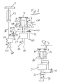
- FIG. 1 In the case of the tilting body 2 formed in FIG. 1 as a dump body, there is a rear wall flap 4 to pivot support arms 6 suspended in the following attached in more detail explained manner.
- the Schwenkhalterungsarme 6 are to an axis indicated at 8 between the in Fig. 1 with solid Lines shown first position, with the closed position of the side wall flap 4 corresponds, and one in Fig. 1 with broken lines pivoted second position shown.
- swivel drive members are hydraulic cylinder-piston units 10th provided, which with its cylinder end in the upper region of the side wall 12 inside the tipping body frame - and with its piston rod end are hinged to the Schwenkhalterungsarmen 6.
- the side wall flap 4 closes the rear side in its closed position Discharge region 14 of the dump body 2.
- FIGS. 2a-2d show that that the side wall flap 4 at the from the pivot axis 8 to the rear protruding Schwenkhalterungsarm is hinged so that they Swiveling the Schwenkhalterungsarms 6 a lifting movement (see Change between Fig. 2a and 2b), in which the locking counter-element 20 of the side wall flap 4 of the locking element 18 is released.
- the pivoting action of Schwenkhalterungsarme 6 stopped in this state of the side wall flap 4, so the unlocked Tailgate flap 4 oscillate about the pendulum axis 22 (see FIG. when the tilting structure is tilted about the tilting axis 19, wherein they have the in Fig. 2c will seek to vertical position and possibly by bulk material is prevented, which in the discharge region 14 of the tilting structure. 2 flows.
- Fig. 3 is a simplified hydraulic circuit diagram is shown, based on which Unlocking and pivoting operation of the side wall flap 4 in more detail below is explained.
- Valve adjustment of the control valve block 34 is accomplished by means of a (not shown) pneumatic adjusting device in accordance with the operation of a e.g. provided in a cab of the dump truck operating device, about a shift lever.
- the tilting cylinder is the Tilting drive means for the tipping design referred.
- the single-acting Tilting cylinder 23 is via the hydraulic line 38 with the tilting valve block 40th for controlling the pressure fluid flow from the pump 42 to the tilt cylinder 23 and connected to the tank 60 for controlling the return flow from the tilting cylinder 23.
- a pressure transfer cylinder 46 In a hydraulic line 38 with the hydraulic line 30 connecting Auxiliary circuit line 44, a pressure transfer cylinder 46 is provided, its cylinder space from a piston 48 into two cylinder chambers 50, 52 is divided. The connected to the hydraulic line 30 cylinder chamber 52 is penetrated by the piston rod 49 of the piston 48. The Rodless cylinder chamber 50 is connected to the pressure fluid line 38.
- the pressure transfer cylinder 46 provides a hydraulic transmission element which comes into effect when the piston 48 at Pressurization in the cylinder chamber 50 performs a piston stroke. He transmits the high pressure to the hydraulic fluid line 30 and thus to the piston rod in Fig. 3 cylinder chambers 54 of the cylinder-piston units 10.
- the control valve block 34 is through check valves (not shown) secured against the pressure from the auxiliary branch 44, so it does not an outflow of pressurized fluid from the auxiliary branch line 44 to the control valve block 34 can come.
- the auxiliary hydraulic circuit comprises in the example the pump 42, the Branch line 44 with the pressure transfer cylinder 46 provided therein and a return path 70 to the tank, this return path a normally-off control valve 72, which depends on the pressure in the line 30 is controlled, such that when pressure is supplied to the cylinder chambers 54 of the cylinder-piston units 10, the control valve 72 on passage is switched to the tank 60. It can then pass through lines 32 and 70, the displaced from the cylinder chambers 61 hydraulic fluid to the tank 60th reach.
- the hydraulic fluid used is preferably oil.
- Fig. 4 shows a simplified hydraulic circuit diagram for a further embodiment the invention. As far as in Fig. 4 functional or representational the same elements as shown in Fig. 3, these elements are in both figures 3 and 4 are each identified by the same reference numerals.
- the pressure transmission cylinder 46 has as large a hydraulic ratio as possible sufficiently large piston rod forces on the cylinder-piston units 10th to create.
- control valve 74 for controlling the pressure fluid flow from the pump 36 to the pressure transfer cylinder 46 or from the pressure transfer cylinder 46 back to Tank 60 is provided.
Landscapes
- Engineering & Computer Science (AREA)
- Transportation (AREA)
- Mechanical Engineering (AREA)
- Actuator (AREA)
- Fluid-Pressure Circuits (AREA)
- Vehicle Body Suspensions (AREA)
- Specific Conveyance Elements (AREA)
- Body Structure For Vehicles (AREA)
- Forklifts And Lifting Vehicles (AREA)
Abstract
Description
- Fig. 1
- zeigt in einer Perspektivdarstellung den Heckbereich eines Kippaufbaus, bei dem es sich im Beispielsfall um eine als Kippmulde ausgebildete Kippbrücke handelt, wobei die Bordwand mit durchgezogenen Linien in der Schließstellung gezeigt ist, wohingegen mit unterbrochenen Linien angedeutet ist, wie die Bordwandklappe in ihrer Stellung maximaler Öffnung des Ausschüttbereichs des Kippaufbaus orientiert ist.
- Fig. 2a-2d
- zeigen in stark vereinfachten schematischen Darstellungen einen Kippaufbau der in Fig. 1 gezeigten Art mit verschiedenen Stellungen der Bordwandklappe.
- Fig. 3
- zeigt ein stark vereinfachtes Hydraulik-Schaltbild zur Erläuterung der hydraulischen Betätigung der Bordwandklappe.
- Fig. 4
- zeigt ein stark vereinfachtes Hydraulikschaltbild eines im Vergleich mit Fig. 3 abgewandelten Ausführungsbeispiels.
Claims (10)
- Kippvorrichtung eines Kipperfahrzeugs, mit einem Kippaufbau (2) und einer hydraulischen Kippantriebseinrichtung (23) zum Schwenken des Kippaufbaus (2) um eine Kippachse (19), wobei der Kippaufbau (2) einen Rahmen (16) und daran wenigstens eine zum Schließen und Öffnen eines Ausschüttbereiches (14) des Kippaufbaus (2) um eine Schwenkachse (8) schwenkbare Bordwandklappe (4), insbesondere Heckwandklappe, und ferner eine die Bordwandklappe (4) in deren Schließstellung verriegelnde Verriegelungseinrichtung (18, 20) aufweist, wobei als Schwenkantriebsvorrichtung für die Bordwandklappe wenigstens eine hydraulische Zylinder-Kolben-Einheit (10) vorgesehen ist, mittels derer auch die Verriegelungseinrichtung (18, 20) betätigbar ist, um die Bordwandklappe (4) aus ihrer Verriegelung freizugeben, wobei die Zylinder-Kolben-Einheit (10) über eine Steuerventilanordnung (34) mit Druck aus einem der Bordwandklappenbetätigung zugeordneten hydraulischen Hauptkreis beaufschlagbar ist, um einen die Öffnungsbewegung der Bordwandklappe (4) auslösenden Kolbenhub der Zylinder-Kolben-Einheit (10) zu erzeugen,
dadurch gekennzeichnet, dass die Zylinder-Kolben-Einheit (10) über einen zumindest dem Entriegelungsvorgang der Verriegelungseinrichtung (18, 20) entsprechenden begrenzten Bereich ihres Kolbenhubs mit einem erhöhten Druck aus einem hydraulischen Hilfskreis bzw. Hilfszweig (44) beaufschlagbar ist. - Kippvorrichtung nach Anspruch 1, gekennzeichnet durch Steuerungsmittel, die dazu eingerichtet sind, mit dem Einleiten des Kippens des Kippaufbaus aus der Fahrbetriebsgrundstellung heraus automatisch den hydraulischen Hilfskreis bzw. Hilfszweig (44) zur Beaufschlagung der Zylinder-Kolben-Einheit (10) zu aktivieren.
- Kippvorrichtung nach Anspruch 1 oder 2, dadurch gekennzeichnet, dass die Verriegelungseinrichtung (18, 20) wenigstens ein am Kippaufbaurahmen (16) in der Nähe des Ausschüttbereiches (14) befestigtes Verriegelungselement (18) aufweist, welches ein Verriegelungsgegenelement (20) der Bordwandklappe (4) in deren Schließstellung verriegelnd hintergreift, wobei die Verriegelung durch Anheben der Bordwandklappe (4) lösbar ist, und dass die Bordwandklappe (4) in der Nähe ihres in der Schließstellung oberen Endes an einer Schwenkhalterungsanordnung (6) angehängt ist, wobei die Schwenkhalterungsanordnung (6) ausgehend von einer mit der Schließstellung der Bordwandklappe (4) korrespondierenden Stellung mittels der Zylinder-Kolben-Einheit (10) um die Schwenkachse (8) schwenkbar ist, um die Bordwandklappe (4) aus ihrer Schließstellung heraus durch Anheben zu entriegeln und in eine Öffnungsstellung zu verschwenken.
- Kippvorrichtung nach Anspruch 3, dadurch gekennzeichnet, dass die Zylinder-Kolben-Einheit (10) in einer Entriegelungsbetriebsart so ansteuerbar ist, dass sie im Wesentlichen nur den zur Entriegelung der Bordwandklappe (4) begrenzten Kolbenhub ausführt, und dass die auf diese Weise entriegelte Bordwandklappe (4) an der Schwenkhalterungsanordnung (6) um eine zur Kippachse (19) parallele Achse pendeln kann, wenn der Kippaufbau (2) in eine angehobene Kippstellung verschwenkt wird.
- Kippvorrichtung nach einem der vorhergehenden Ansprüche, dadurch gekennzeichnet, dass der hydraulische Hilfskreis bzw. Hilfszweig (44) an der Druckseite einer Pumpe (42) zur hydraulischen Versorgung der Kippantriebseinrichtung (23) angeschlossen ist.
- Kippvorrichtung nach einem der vorhergehenden Ansprüche, dadurch gekennzeichnet, dass der hydraulische Hilfskreis bzw. Hilfszweig (44) und der hydraulische Hauptkreis von unterschiedlichen Pumpen (36, 42) mit Druckfluid versorgt werden.
- Kippvorrichtung nach einem der Ansprüche 1 bis 5, dadurch gekennzeichnet, dass der hydraulische Hilfskreis bzw. Hilfszweig und der hydraulische Hauptkreis von derselben Pumpe (36, Fig. 4) mit Druckfluid versorgt werden.
- Kippvorrichtung nach einem der vorhergehenden Ansprüche, dadurch gekennzeichnet, dass der hydraulische Hilfskreis bzw. Hilfszweig (44) einen insbesondere hydraulisch übersetzenden Druckübertragungszylinder (46) enthält.
- Kippvorrichtung nach Anspruch 8, dadurch gekennzeichnet, dass der Druckübertragungszylinder (46) innen von einem einseitig eine Kolbenstange (49) aufweisenden Kolben (48) in zwei Zylinderkammern (50, 52) unterteilt ist, wobei die von der Kolbenstange (49) durchsetzte Zylinderkammer (52) hydraulisch mit der Zylinder-Kolben-Einheit (10) für die Entriegelung und für den Schwenkantrieb der Bordwandklappe (4) in Verbindung steht, wohingegen die andere Zylinderkammer (50) ggf. über eine Ventilanordnung an einer Druckfluid fördernden Pumpe (42) angeschlossen ist, und wobei der Druckübertragungszylinder (46) so dimensioniert ist, dass die von ihm bei einem vollständigen Maximalhub seines Kolbens (48) zu der Zylinder-Kolben-Einheit (10) verdrängte Druckfluidmenge ausreicht, um bei der Zylinder-Kolben-Einheit (10) einen im Wesentlichen auf den Entriegelungsvorgang der Verriegelungseinrichtung (18, 20) begrenzten Kolbenhub zu verursachen.
- Kippvorrichtung nach Anspruch 9, dadurch gekennzeichnet, dass der Druckübertragungszylinder (46) so an einem Fahrzeugrahmenteil oder dazu ortsfest angeordnet ist, dass er mechanisch von dem Kippaufbau (2) in Eingriff genommen werden kann, um die Kolbenstange (49) in die eingezogene Grundstellung im Druckübertragungszylinder zu überführen, wenn der Kippaufbau (2) aus einer angehobenen Kippstellung in die Fahrbetriebsgrundstellung übergeht.
Applications Claiming Priority (2)
| Application Number | Priority Date | Filing Date | Title |
|---|---|---|---|
| DE10348605A DE10348605A1 (de) | 2003-10-20 | 2003-10-20 | Kippvorrichtung eines Kipperfahrzeugs |
| DE10348605 | 2003-10-20 |
Publications (2)
| Publication Number | Publication Date |
|---|---|
| EP1526036A1 true EP1526036A1 (de) | 2005-04-27 |
| EP1526036B1 EP1526036B1 (de) | 2009-04-08 |
Family
ID=34384377
Family Applications (1)
| Application Number | Title | Priority Date | Filing Date |
|---|---|---|---|
| EP04022566A Expired - Lifetime EP1526036B1 (de) | 2003-10-20 | 2004-09-22 | Kippvorrichtung eines Kipperfahrzeugs |
Country Status (3)
| Country | Link |
|---|---|
| EP (1) | EP1526036B1 (de) |
| AT (1) | ATE427856T1 (de) |
| DE (2) | DE10348605A1 (de) |
Cited By (2)
| Publication number | Priority date | Publication date | Assignee | Title |
|---|---|---|---|---|
| CN100497041C (zh) * | 2006-07-24 | 2009-06-10 | 赵永胜 | 具有自动液控尾挡板的自卸车 |
| CN106965738A (zh) * | 2017-04-28 | 2017-07-21 | 山东嵘野房车制造服务有限公司 | 一种前后双翻式牵引式房车 |
Families Citing this family (3)
| Publication number | Priority date | Publication date | Assignee | Title |
|---|---|---|---|---|
| DE202011052015U1 (de) | 2011-11-18 | 2013-03-20 | Kögel Trailer GmbH & Co. KG | Fahrzeugaufbau |
| DE202015105380U1 (de) | 2015-10-12 | 2017-01-13 | Ulrich Humbaur | Riegeleinrichtung für Pendelbordwand |
| DE102017221065A1 (de) * | 2017-11-24 | 2019-05-29 | Franz Xaver Meiller Fahrzeug- Und Maschinenfabrik - Gmbh & Co Kg | Bordwandvorrichtung eines Lastentransportbehälters eines Lastentransportfahrzeugs |
Citations (5)
| Publication number | Priority date | Publication date | Assignee | Title |
|---|---|---|---|---|
| US4307541A (en) * | 1979-11-30 | 1981-12-29 | Dempster Systems Inc. | Tail-gate operating and locking mechanism |
| DE29507084U1 (de) * | 1995-04-27 | 1995-06-29 | Maschinenbau Otto Gruber Ges.M.B.H., Saalfelden | Hydraulisch betätigbare Rückwand |
| DE4417766A1 (de) * | 1994-05-20 | 1995-11-23 | Gerhard Spaegele | Heckbordwand für Kipperfahrzeuge |
| DE19940811A1 (de) * | 1999-08-27 | 2001-03-08 | Meiller Fahrzeuge | Bordwandeinrichtung mit einer Bordwandklappe für einen Transportbehälteraufbau, insbesondere Kippbrücke, eines Lastentransportfahrzeugs |
| US6572197B1 (en) * | 2001-05-11 | 2003-06-03 | Joel E. Clough | Vehicle latch assembly |
-
2003
- 2003-10-20 DE DE10348605A patent/DE10348605A1/de not_active Withdrawn
-
2004
- 2004-09-22 DE DE502004009301T patent/DE502004009301D1/de not_active Expired - Lifetime
- 2004-09-22 EP EP04022566A patent/EP1526036B1/de not_active Expired - Lifetime
- 2004-09-22 AT AT04022566T patent/ATE427856T1/de active
Patent Citations (5)
| Publication number | Priority date | Publication date | Assignee | Title |
|---|---|---|---|---|
| US4307541A (en) * | 1979-11-30 | 1981-12-29 | Dempster Systems Inc. | Tail-gate operating and locking mechanism |
| DE4417766A1 (de) * | 1994-05-20 | 1995-11-23 | Gerhard Spaegele | Heckbordwand für Kipperfahrzeuge |
| DE29507084U1 (de) * | 1995-04-27 | 1995-06-29 | Maschinenbau Otto Gruber Ges.M.B.H., Saalfelden | Hydraulisch betätigbare Rückwand |
| DE19940811A1 (de) * | 1999-08-27 | 2001-03-08 | Meiller Fahrzeuge | Bordwandeinrichtung mit einer Bordwandklappe für einen Transportbehälteraufbau, insbesondere Kippbrücke, eines Lastentransportfahrzeugs |
| US6572197B1 (en) * | 2001-05-11 | 2003-06-03 | Joel E. Clough | Vehicle latch assembly |
Cited By (3)
| Publication number | Priority date | Publication date | Assignee | Title |
|---|---|---|---|---|
| CN100497041C (zh) * | 2006-07-24 | 2009-06-10 | 赵永胜 | 具有自动液控尾挡板的自卸车 |
| CN106965738A (zh) * | 2017-04-28 | 2017-07-21 | 山东嵘野房车制造服务有限公司 | 一种前后双翻式牵引式房车 |
| CN106965738B (zh) * | 2017-04-28 | 2024-03-19 | 山东嵘野房车制造服务有限公司 | 一种前后双翻式牵引式房车 |
Also Published As
| Publication number | Publication date |
|---|---|
| ATE427856T1 (de) | 2009-04-15 |
| DE10348605A1 (de) | 2005-06-30 |
| EP1526036B1 (de) | 2009-04-08 |
| DE502004009301D1 (de) | 2009-05-20 |
Similar Documents
| Publication | Publication Date | Title |
|---|---|---|
| EP2799283B1 (de) | Lastentransportfahrzeug mit einem Wechselbehälter und einem Hubgerät für den Wechselbehälter | |
| DE2066194C2 (de) | ||
| EP1526036B1 (de) | Kippvorrichtung eines Kipperfahrzeugs | |
| DE102004025928A1 (de) | Steuereinrichtung zur Steuerung einer hydraulischen Antriebseinrichtung eines Lastenbewegungsgerätes, insbesondere einer Schwenkarmanordnung als Hubgerät für Wechselbehälter auf einem Lastentransportfahrzeug | |
| EP3247661B1 (de) | Kippvorrichtung sowie verfahren zum betreiben einer kippvorrichtung | |
| EP2918445A1 (de) | Absetzkipperfahrzeug | |
| EP1702792B1 (de) | Hubgerät für Wechselbehälter auf einem Lastentransportfahrzeug | |
| DE10063610B4 (de) | Steuereinrichtung zur Steuerung einer hydraulischen Schwenkantriebsvorrichtung | |
| DE19509490A1 (de) | Kippvorrichtung für ein Fahrerhaus eines Nutzfahrzeuges | |
| EP4001027A1 (de) | Hydrauliksystem für ein fahrzeug oder einen container sowie fahrzeug oder container mit einem solchen hydrauliksystem | |
| EP0893605B1 (de) | Hydraulische Betätigungsanordnung | |
| DE2200879A1 (de) | Einrichtung zum anheben von lasten | |
| EP4001006B1 (de) | Vorrichtung zur verriegelung einer behälterklappe | |
| DE1248541B (de) | Hubkippvorrichtung zum Entleeren von Muellgefaessen in staubfreie Einschuettvorrichtungen an Muellsammelwagen | |
| EP4489995B1 (de) | Anhebe- und absenkanordnung für containerverriegelung und anhebe- und absenkverfahren damit | |
| DE9317545U1 (de) | Schwenkbare Bordwand eines Transportfahrzeugs | |
| DE1270494B (de) | Schaufellader | |
| AT200181B (de) | Kippwagen | |
| CH351626A (de) | Kippwagen | |
| AT404173B (de) | Rückschlagventil | |
| DE102005044897B4 (de) | Hydraulische Antriebs- und Steuerungsvorrichtung und Verfahren zum Betrieb derselben | |
| DE2201683B1 (de) | Kraneinrichtung | |
| DE4417766A1 (de) | Heckbordwand für Kipperfahrzeuge | |
| WO1979000032A1 (fr) | Dispositif de levage et d'abaissement pour basculer une plateforme de chargement, notamment pour camions et remorques | |
| EP0610580A1 (de) | Rückwand für Ladewagen |
Legal Events
| Date | Code | Title | Description |
|---|---|---|---|
| PUAI | Public reference made under article 153(3) epc to a published international application that has entered the european phase |
Free format text: ORIGINAL CODE: 0009012 |
|
| AK | Designated contracting states |
Kind code of ref document: A1 Designated state(s): AT BE BG CH CY CZ DE DK EE ES FI FR GB GR HU IE IT LI LU MC NL PL PT RO SE SI SK TR |
|
| AX | Request for extension of the european patent |
Extension state: AL HR LT LV MK |
|
| 17P | Request for examination filed |
Effective date: 20050926 |
|
| AKX | Designation fees paid |
Designated state(s): AT BE BG CH CY CZ DE DK EE ES FI FR GB GR HU IE IT LI LU MC NL PL PT RO SE SI SK TR |
|
| AXX | Extension fees paid |
Extension state: HR Payment date: 20050926 Extension state: LV Payment date: 20050926 Extension state: MK Payment date: 20050926 Extension state: LT Payment date: 20050926 |
|
| GRAP | Despatch of communication of intention to grant a patent |
Free format text: ORIGINAL CODE: EPIDOSNIGR1 |
|
| GRAS | Grant fee paid |
Free format text: ORIGINAL CODE: EPIDOSNIGR3 |
|
| GRAA | (expected) grant |
Free format text: ORIGINAL CODE: 0009210 |
|
| AK | Designated contracting states |
Kind code of ref document: B1 Designated state(s): AT BE BG CH CY CZ DE DK EE ES FI FR GB GR HU IE IT LI LU MC NL PL PT RO SE SI SK TR |
|
| AX | Request for extension of the european patent |
Extension state: HR LT LV MK |
|
| REG | Reference to a national code |
Ref country code: GB Ref legal event code: FG4D Free format text: NOT ENGLISH |
|
| REG | Reference to a national code |
Ref country code: CH Ref legal event code: EP |
|
| REG | Reference to a national code |
Ref country code: IE Ref legal event code: FG4D |
|
| REF | Corresponds to: |
Ref document number: 502004009301 Country of ref document: DE Date of ref document: 20090520 Kind code of ref document: P |
|
| PG25 | Lapsed in a contracting state [announced via postgrant information from national office to epo] |
Ref country code: SI Free format text: LAPSE BECAUSE OF FAILURE TO SUBMIT A TRANSLATION OF THE DESCRIPTION OR TO PAY THE FEE WITHIN THE PRESCRIBED TIME-LIMIT Effective date: 20090408 |
|
| LTIE | Lt: invalidation of european patent or patent extension |
Effective date: 20090408 |
|
| REG | Reference to a national code |
Ref country code: IE Ref legal event code: FD4D |
|
| PG25 | Lapsed in a contracting state [announced via postgrant information from national office to epo] |
Ref country code: PT Free format text: LAPSE BECAUSE OF FAILURE TO SUBMIT A TRANSLATION OF THE DESCRIPTION OR TO PAY THE FEE WITHIN THE PRESCRIBED TIME-LIMIT Effective date: 20090908 Ref country code: FI Free format text: LAPSE BECAUSE OF FAILURE TO SUBMIT A TRANSLATION OF THE DESCRIPTION OR TO PAY THE FEE WITHIN THE PRESCRIBED TIME-LIMIT Effective date: 20090408 Ref country code: ES Free format text: LAPSE BECAUSE OF FAILURE TO SUBMIT A TRANSLATION OF THE DESCRIPTION OR TO PAY THE FEE WITHIN THE PRESCRIBED TIME-LIMIT Effective date: 20090719 |
|
| PG25 | Lapsed in a contracting state [announced via postgrant information from national office to epo] |
Ref country code: PL Free format text: LAPSE BECAUSE OF FAILURE TO SUBMIT A TRANSLATION OF THE DESCRIPTION OR TO PAY THE FEE WITHIN THE PRESCRIBED TIME-LIMIT Effective date: 20090408 Ref country code: SE Free format text: LAPSE BECAUSE OF FAILURE TO SUBMIT A TRANSLATION OF THE DESCRIPTION OR TO PAY THE FEE WITHIN THE PRESCRIBED TIME-LIMIT Effective date: 20090708 |
|
| PG25 | Lapsed in a contracting state [announced via postgrant information from national office to epo] |
Ref country code: EE Free format text: LAPSE BECAUSE OF FAILURE TO SUBMIT A TRANSLATION OF THE DESCRIPTION OR TO PAY THE FEE WITHIN THE PRESCRIBED TIME-LIMIT Effective date: 20090408 Ref country code: DK Free format text: LAPSE BECAUSE OF FAILURE TO SUBMIT A TRANSLATION OF THE DESCRIPTION OR TO PAY THE FEE WITHIN THE PRESCRIBED TIME-LIMIT Effective date: 20090408 Ref country code: RO Free format text: LAPSE BECAUSE OF FAILURE TO SUBMIT A TRANSLATION OF THE DESCRIPTION OR TO PAY THE FEE WITHIN THE PRESCRIBED TIME-LIMIT Effective date: 20090408 Ref country code: IE Free format text: LAPSE BECAUSE OF FAILURE TO SUBMIT A TRANSLATION OF THE DESCRIPTION OR TO PAY THE FEE WITHIN THE PRESCRIBED TIME-LIMIT Effective date: 20090408 Ref country code: CZ Free format text: LAPSE BECAUSE OF FAILURE TO SUBMIT A TRANSLATION OF THE DESCRIPTION OR TO PAY THE FEE WITHIN THE PRESCRIBED TIME-LIMIT Effective date: 20090408 |
|
| PLBE | No opposition filed within time limit |
Free format text: ORIGINAL CODE: 0009261 |
|
| STAA | Information on the status of an ep patent application or granted ep patent |
Free format text: STATUS: NO OPPOSITION FILED WITHIN TIME LIMIT |
|
| PG25 | Lapsed in a contracting state [announced via postgrant information from national office to epo] |
Ref country code: SK Free format text: LAPSE BECAUSE OF FAILURE TO SUBMIT A TRANSLATION OF THE DESCRIPTION OR TO PAY THE FEE WITHIN THE PRESCRIBED TIME-LIMIT Effective date: 20090408 |
|
| 26N | No opposition filed |
Effective date: 20100111 |
|
| BERE | Be: lapsed |
Owner name: FRANZ XAVER MEILLER FAHRZEUG- UND MASCHINENFABRIK Effective date: 20090930 |
|
| PG25 | Lapsed in a contracting state [announced via postgrant information from national office to epo] |
Ref country code: BG Free format text: LAPSE BECAUSE OF FAILURE TO SUBMIT A TRANSLATION OF THE DESCRIPTION OR TO PAY THE FEE WITHIN THE PRESCRIBED TIME-LIMIT Effective date: 20090708 |
|
| PG25 | Lapsed in a contracting state [announced via postgrant information from national office to epo] |
Ref country code: MC Free format text: LAPSE BECAUSE OF NON-PAYMENT OF DUE FEES Effective date: 20090930 |
|
| REG | Reference to a national code |
Ref country code: CH Ref legal event code: PL |
|
| GBPC | Gb: european patent ceased through non-payment of renewal fee |
Effective date: 20090922 |
|
| PG25 | Lapsed in a contracting state [announced via postgrant information from national office to epo] |
Ref country code: BE Free format text: LAPSE BECAUSE OF NON-PAYMENT OF DUE FEES Effective date: 20090930 |
|
| PG25 | Lapsed in a contracting state [announced via postgrant information from national office to epo] |
Ref country code: GR Free format text: LAPSE BECAUSE OF FAILURE TO SUBMIT A TRANSLATION OF THE DESCRIPTION OR TO PAY THE FEE WITHIN THE PRESCRIBED TIME-LIMIT Effective date: 20090709 Ref country code: CH Free format text: LAPSE BECAUSE OF NON-PAYMENT OF DUE FEES Effective date: 20090930 Ref country code: LI Free format text: LAPSE BECAUSE OF NON-PAYMENT OF DUE FEES Effective date: 20090930 |
|
| PG25 | Lapsed in a contracting state [announced via postgrant information from national office to epo] |
Ref country code: GB Free format text: LAPSE BECAUSE OF NON-PAYMENT OF DUE FEES Effective date: 20090922 |
|
| PG25 | Lapsed in a contracting state [announced via postgrant information from national office to epo] |
Ref country code: IT Free format text: LAPSE BECAUSE OF FAILURE TO SUBMIT A TRANSLATION OF THE DESCRIPTION OR TO PAY THE FEE WITHIN THE PRESCRIBED TIME-LIMIT Effective date: 20090408 |
|
| PG25 | Lapsed in a contracting state [announced via postgrant information from national office to epo] |
Ref country code: LU Free format text: LAPSE BECAUSE OF NON-PAYMENT OF DUE FEES Effective date: 20090922 |
|
| PG25 | Lapsed in a contracting state [announced via postgrant information from national office to epo] |
Ref country code: HU Free format text: LAPSE BECAUSE OF FAILURE TO SUBMIT A TRANSLATION OF THE DESCRIPTION OR TO PAY THE FEE WITHIN THE PRESCRIBED TIME-LIMIT Effective date: 20091009 |
|
| PG25 | Lapsed in a contracting state [announced via postgrant information from national office to epo] |
Ref country code: TR Free format text: LAPSE BECAUSE OF FAILURE TO SUBMIT A TRANSLATION OF THE DESCRIPTION OR TO PAY THE FEE WITHIN THE PRESCRIBED TIME-LIMIT Effective date: 20090408 |
|
| PG25 | Lapsed in a contracting state [announced via postgrant information from national office to epo] |
Ref country code: CY Free format text: LAPSE BECAUSE OF FAILURE TO SUBMIT A TRANSLATION OF THE DESCRIPTION OR TO PAY THE FEE WITHIN THE PRESCRIBED TIME-LIMIT Effective date: 20090408 |
|
| REG | Reference to a national code |
Ref country code: FR Ref legal event code: PLFP Year of fee payment: 13 |
|
| PGFP | Annual fee paid to national office [announced via postgrant information from national office to epo] |
Ref country code: NL Payment date: 20160920 Year of fee payment: 13 |
|
| REG | Reference to a national code |
Ref country code: FR Ref legal event code: PLFP Year of fee payment: 14 |
|
| REG | Reference to a national code |
Ref country code: NL Ref legal event code: MM Effective date: 20171001 |
|
| PG25 | Lapsed in a contracting state [announced via postgrant information from national office to epo] |
Ref country code: NL Free format text: LAPSE BECAUSE OF NON-PAYMENT OF DUE FEES Effective date: 20171001 |
|
| REG | Reference to a national code |
Ref country code: FR Ref legal event code: PLFP Year of fee payment: 15 |
|
| PGFP | Annual fee paid to national office [announced via postgrant information from national office to epo] |
Ref country code: AT Payment date: 20190919 Year of fee payment: 16 |
|
| PGFP | Annual fee paid to national office [announced via postgrant information from national office to epo] |
Ref country code: DE Payment date: 20200731 Year of fee payment: 17 Ref country code: FR Payment date: 20200914 Year of fee payment: 17 |
|
| REG | Reference to a national code |
Ref country code: AT Ref legal event code: MM01 Ref document number: 427856 Country of ref document: AT Kind code of ref document: T Effective date: 20200922 |
|
| PG25 | Lapsed in a contracting state [announced via postgrant information from national office to epo] |
Ref country code: AT Free format text: LAPSE BECAUSE OF NON-PAYMENT OF DUE FEES Effective date: 20200922 |
|
| REG | Reference to a national code |
Ref country code: DE Ref legal event code: R119 Ref document number: 502004009301 Country of ref document: DE |
|
| PG25 | Lapsed in a contracting state [announced via postgrant information from national office to epo] |
Ref country code: FR Free format text: LAPSE BECAUSE OF NON-PAYMENT OF DUE FEES Effective date: 20210930 Ref country code: DE Free format text: LAPSE BECAUSE OF NON-PAYMENT OF DUE FEES Effective date: 20220401 |