EP1525923A1 - Handbetätigbare Pumpe zur Abgabe von zerstäubten Flüssigkeiten in der Überkopfstellung - Google Patents
Handbetätigbare Pumpe zur Abgabe von zerstäubten Flüssigkeiten in der Überkopfstellung Download PDFInfo
- Publication number
- EP1525923A1 EP1525923A1 EP04023653A EP04023653A EP1525923A1 EP 1525923 A1 EP1525923 A1 EP 1525923A1 EP 04023653 A EP04023653 A EP 04023653A EP 04023653 A EP04023653 A EP 04023653A EP 1525923 A1 EP1525923 A1 EP 1525923A1
- Authority
- EP
- European Patent Office
- Prior art keywords
- pump
- chamber
- main body
- liquid
- dip tube
- Prior art date
- Legal status (The legal status is an assumption and is not a legal conclusion. Google has not performed a legal analysis and makes no representation as to the accuracy of the status listed.)
- Granted
Links
- 239000007788 liquid Substances 0.000 title claims abstract description 38
- 230000006835 compression Effects 0.000 claims description 10
- 238000007906 compression Methods 0.000 claims description 10
- 238000004891 communication Methods 0.000 claims description 9
- 230000002093 peripheral effect Effects 0.000 claims description 3
- 238000007789 sealing Methods 0.000 description 3
- 230000000694 effects Effects 0.000 description 2
- 230000000717 retained effect Effects 0.000 description 2
- 244000273618 Sphenoclea zeylanica Species 0.000 description 1
- 238000010276 construction Methods 0.000 description 1
- 239000002537 cosmetic Substances 0.000 description 1
- 238000004519 manufacturing process Methods 0.000 description 1
- 230000037452 priming Effects 0.000 description 1
- 238000005086 pumping Methods 0.000 description 1
- 230000002441 reversible effect Effects 0.000 description 1
- 230000000630 rising effect Effects 0.000 description 1
Images

Classifications
-
- B—PERFORMING OPERATIONS; TRANSPORTING
- B05—SPRAYING OR ATOMISING IN GENERAL; APPLYING FLUENT MATERIALS TO SURFACES, IN GENERAL
- B05B—SPRAYING APPARATUS; ATOMISING APPARATUS; NOZZLES
- B05B11/00—Single-unit hand-held apparatus in which flow of contents is produced by the muscular force of the operator at the moment of use
- B05B11/01—Single-unit hand-held apparatus in which flow of contents is produced by the muscular force of the operator at the moment of use characterised by the means producing the flow
- B05B11/10—Pump arrangements for transferring the contents from the container to a pump chamber by a sucking effect and forcing the contents out through the dispensing nozzle
- B05B11/1042—Components or details
- B05B11/1061—Pump priming means
-
- B—PERFORMING OPERATIONS; TRANSPORTING
- B05—SPRAYING OR ATOMISING IN GENERAL; APPLYING FLUENT MATERIALS TO SURFACES, IN GENERAL
- B05B—SPRAYING APPARATUS; ATOMISING APPARATUS; NOZZLES
- B05B11/00—Single-unit hand-held apparatus in which flow of contents is produced by the muscular force of the operator at the moment of use
- B05B11/0005—Components or details
- B05B11/0059—Components or details allowing operation in any orientation, e.g. for discharge in inverted position
-
- B—PERFORMING OPERATIONS; TRANSPORTING
- B05—SPRAYING OR ATOMISING IN GENERAL; APPLYING FLUENT MATERIALS TO SURFACES, IN GENERAL
- B05B—SPRAYING APPARATUS; ATOMISING APPARATUS; NOZZLES
- B05B11/00—Single-unit hand-held apparatus in which flow of contents is produced by the muscular force of the operator at the moment of use
- B05B11/01—Single-unit hand-held apparatus in which flow of contents is produced by the muscular force of the operator at the moment of use characterised by the means producing the flow
- B05B11/10—Pump arrangements for transferring the contents from the container to a pump chamber by a sucking effect and forcing the contents out through the dispensing nozzle
- B05B11/1001—Piston pumps
Definitions
- the present invention relates to a manually operable invertible pump for dispensing atomized liquids withdrawn from a liquid container, on the mouth of which the pump is mounted usable both in the upright position, i.e. with the pump facing upwards from the container, and in the inverted position, i.e. with the pump facing downwards from the container.
- invertible pumps are known, such as those described in US-A-5222636, US-A-4775079, US-A-4277001, US-A-5738252, EP-A-0648545 and EP-A-1029597, however such pumps have serious drawbacks which limit their production and use.
- an invertible pump depends on the fact that the liquid enclosed in a container must be able to penetrate into the pump compression chamber by rising along a dip tube (of which one end is mounted on the pump and the other end is free and is positioned in proximity to the container base) when the pump is upright above the container, but to penetrate directly into said compression chamber from a hole provided in the pump body, and of which the opening is controlled by a unidirectional valve which opens only during pump intake and only when the pump is inverted, i.e. positioned below the container.
- a dip tube of which one end is mounted on the pump and the other end is free and is positioned in proximity to the container base
- the main object of the present invention is to provide an invertible pump having a structure which is very simple to mould and assemble, and of easy and economical construction, and in particular having a length and width (below and respectively laterally to the pump body) which only slightly exceed the dimensions of a similar non-invertible pump.
- an invertible pump comprising a main body defining a chamber for the intake and compression of determined quantities of the liquid to be dispensed, a dip tube connected to said chamber via a hole provided in the base wall of the main body and via a first unidirectional valve system which enables the liquid to arrive in said chamber through the dip tube when the pump is upright but prevents liquid arrival when the pump is inverted, there being provided in the main body an aperture provided with a second unidirectional valve system which enables the liquid to directly arrive in the compression chamber when the pump is inverted but prevents this arrival when the pump is upright, characterised in that said second valve system comprises a cup-shaped body sealedly mounted on the outer peripheral surface of the main body to define with the adjacent extremity on the said main body an annular chamber housing and retaining a flexible element which when the pump is at rest or being used in the upright position is elastically urged to seal against a profiled edge provided on the base wall of the cup-shaped body, said annular chamber being in direct communication with said intake and compression
- a tubular element is provided projecting from one and the other side of said central hole of the flexible element, the two free ends of said tubular element being sealedly fixed rigidly to the dip tube and, respectively, to that hole of the main body to which the tube is connected.
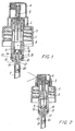
- the pump shown in Figures from 1 to 4 comprises a main body 1 housing a sealedly slidable piston 2, from which there extends a hollow stem 3, the free end of which is inserted into a suitable seat provided in a dispensing cap 4: the body 1 can be rigidly fixed by a threaded ring cap 5 onto the mouth of a container (not shown for simplicity) for the liquid to be dispensed.
- the main body 1 is lowerly bounded by a base wall 6, in the centre of which there is provided a hole connectable to a dip tube 7 which enables the liquid present in the container to rise (when the pump is in the upright position of Figures 1 and 2) through the hole in the base wall 6 and to penetrate into the liquid intake and compression chamber bounded within the body 1 by the piston 2 and by a unidirectional seal valve which, in the illustrated example, consists of a small plastic ball 9 housed and axially translatable within a housing 10 projecting from the base wall 6, where a profiled seat is provided on which the ball 9 rests and forms a seal when a liquid present in the chamber 8 is put under pressure by operating the cap 6 and with it the stem 3 and piston 2.
- a unidirectional seal valve which, in the illustrated example, consists of a small plastic ball 9 housed and axially translatable within a housing 10 projecting from the base wall 6, where a profiled seat is provided on which the ball 9 rests and forms a seal when a liquid present
- the pump as described up to this point is of known type and can be structured in various ways: for example that shown in Figures 1-4 is totally similar to that illustrated in EP-B-0721803 (but could be as that illustrated in EP-A-1334774, EP-A-0648545, US-A-3627206 or many others).
- the new and characteristic part of the pump of the invention relates to the lower part of the pump (with reference to the pump in its upright position of Figures 1 and 2), where it can be seen that on the outer surface of the main body 1 there is sealedly mounted a cup-shaped body 11 having a base wall 12 which defines an annular chamber 13 with the adjacent end of the body 1, the chamber 13 being in free communication with the chamber 8 via an aperture 14 provided in the main body 1 and left free by the cup-shaped body.
- a flexible discoidal element 15 having a central hole, from one and the other side of which there project two small tubular elements 16, 17, one of which is sealedly inserted and securely retained in a suitable seat (for simplicity not numbered, but clearly visible in the drawings) provided in the base wall 12 of the body 1 where a hole (also not numbered) is provided at the centre of the housing 10, on the profiled seat of which the ball 9 can form a seal; whereas the other tubular element 17 is inserted into and sealedly retained in the cavity of a hole provided at the centre of the base wall 12, from this hole there extending a hollow appendix 18, on the end of which the dip tube 7 is mounted.
- a suitable seat for simplicity not numbered, but clearly visible in the drawings
- the hollow appendix 18 houses an axially translatable small ball 20, which cannot escape from the cavity in the appendix because inside this appendix there is provided a ledge or the like on which the ball can rest (with the pump upright) without however closing the hole of the appendix, in which one or more longitudinal grooves are provided (not numbered for simplicity but clearly visible in the drawings), to leave the passage free for the liquid which rises from the dip tube to the pump.
- the ball 20 can be inserted into the appendix 18 by simply allowing it to fall freely into the cup-shaped body 11 before this is mounted in the pump; the tubular element 16 can be easily inserted into its seat in the pump, either before mounting the cup-shaped body on the pump, or by firstly inserting and locking the tubular element 17 in its seat in the hollow appendix 18 and then mounting the cup-shaped body on the pump, so automatically inserting the tubular element 16 in its seat.
- transverse and longitudinal dimensions of the invertible pump are only slightly greater than those of a common non-invertible pump of similar structure.
- the cap 4 is pressed with a finger to lower the piston 2 from the position of Figure 1 to that of Figure 2, while the air initially present in the pump chamber is expelled to the outside in traditional known manner, as described in a large number of patents, including those already cited.
- the pump With the pump hence primed and upright, the pump is again operated to pressurize the liquid present in the chamber 8 and force the ball 9 to press and seal against its seat: the liquid which fills the annular chamber 13 and is in communication with the chamber 8 via the aperture 14 cannot escape to the outside of the pump body because the flexible discoidal element 15 is urged by the pressurized liquid to seal against the annular projection provided on the base of the cup-shaped body.
- the pump can hence be used in the same manner as a common non-invertible pump of similar structure.
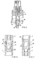
- the pressurized liquid present in the chamber 8 urges the discoidal element 15 against the profiled rim of the cup-shaped body (hence increasing the seal effect) and lifts the ball 9, which becomes inserted into and seals against its seat in the housing 10, this position being maintained until the piston 2 reaches its end-of-travel position ( Figure 3).
- the body 101 defines an intake and compression chamber 108 and presents an aperture 114 which is left free by a cup-shaped body 111 sealedly mounted on the lower end of the body 101.
- An elongate hollow appendix 150 projects from the base 106 of the body 101 and houses two small sealing balls 109, 120 (identical to the already described balls 9 and 20 and having the same function): a dip tube 107 is sealedly mounted on the free end of the appendix 150, there also being mounted on said aperture (but positioned within the cup-shaped body 111) a flexible discoidal element with a central hole (to enable it to be mounted on the appendix 150), its free ends when in the rest condition being elastically urged to form a seal against a profiled rim projecting from the base of the cup-shaped body, so preventing communication between one or more holes 119 provided in the base of the cup-shaped body and the chamber 113, which is in direct communication with the aperture 114.
- the liquid drawn through the dip tube 7 passes through the open free end of the hollow appendix 18, flows around the ball 20 and then rises above the ball 20 to enter the intake chamber 8.
- the liquid takes an identical path from the dip tube to the intake chamber in the pump of Figure 5.
- Grooves 219 are provided in the outer surface of the hollow appendix 218, each opening in correspondence with a respective aperture 220 which connects the internal cavity of the appendix 218 to each groove 219.
- Figure 7 is similar to Figure 6 but shows the position assumed by the ball 20 when the pump is used in the inverted position.
- Figures 6 and 7 relate to the embodiment of Figures 1-4, however the same structural variant (i.e. the presence of the grooves on the outside of the hollow appendix on which the dip tube is mounted, and the presence of apertures which pass through the thickness of the hollow appendix in correspondence with said grooves) can evidently also be applied if the pump is that shown in Figure 5.
Landscapes
- Reciprocating Pumps (AREA)
- Containers And Packaging Bodies Having A Special Means To Remove Contents (AREA)
- Closures For Containers (AREA)
- Catching Or Destruction (AREA)
- Special Spraying Apparatus (AREA)
Applications Claiming Priority (2)
| Application Number | Priority Date | Filing Date | Title |
|---|---|---|---|
| IT002082A ITMI20032082A1 (it) | 2003-10-24 | 2003-10-24 | Pompa invertibile azionabile a mano per l'erogazione di liquidi atomizzati |
| ITMI20032082 | 2003-10-24 |
Publications (2)
| Publication Number | Publication Date |
|---|---|
| EP1525923A1 true EP1525923A1 (de) | 2005-04-27 |
| EP1525923B1 EP1525923B1 (de) | 2006-01-11 |
Family
ID=34385822
Family Applications (1)
| Application Number | Title | Priority Date | Filing Date |
|---|---|---|---|
| EP04023653A Expired - Lifetime EP1525923B1 (de) | 2003-10-24 | 2004-10-05 | Handbetätigbare Pumpe zur Abgabe von zerstäubten Flüssigkeiten in der Überkopfstellung |
Country Status (7)
| Country | Link |
|---|---|
| US (1) | US6942125B2 (de) |
| EP (1) | EP1525923B1 (de) |
| AT (1) | ATE315443T1 (de) |
| CA (1) | CA2484408A1 (de) |
| DE (1) | DE602004000312T2 (de) |
| ES (1) | ES2256816T3 (de) |
| IT (1) | ITMI20032082A1 (de) |
Cited By (1)
| Publication number | Priority date | Publication date | Assignee | Title |
|---|---|---|---|---|
| WO2008003076A3 (en) * | 2006-06-29 | 2008-06-05 | Meadwestvaco Corp | Pumps and methods for using the same |
Families Citing this family (10)
| Publication number | Priority date | Publication date | Assignee | Title |
|---|---|---|---|---|
| ITMI20032162A1 (it) * | 2003-11-10 | 2005-05-11 | Microspray Delta Spa | Pompa invertibile per l'erogazione di liquidi atomizzati, |
| DE102004048248B3 (de) * | 2004-10-04 | 2006-02-09 | Seaquist Perfect Dispensing Gmbh | Adapter für eine handbetätigte Abgabevorrichtung für Flüssigkeitsbehälter |
| NL1028577C2 (nl) * | 2005-03-21 | 2006-09-25 | Afa Polytek Bv | Doseerkop voor het afgeven van fluïdum uit een houder. |
| US8336740B1 (en) * | 2005-11-02 | 2012-12-25 | Daansen Warren S | Fluid dispenser and pump adapter system therefor |
| US9242256B2 (en) | 2007-07-17 | 2016-01-26 | S.C. Johnson & Son, Inc. | Aerosol dispenser assembly having VOC-free propellant and dispensing mechanism therefor |
| US8087548B2 (en) * | 2008-05-14 | 2012-01-03 | S.C. Johnson & Son, Inc. | Spray products with particles and improved valve for inverted dispensing without clogging |
| ITMI20091648A1 (it) * | 2009-09-25 | 2011-03-26 | Modapack S R L | "gruppo per la pressurizzazione e l'erogazione di sostanze fluide per una pompa ad azionamento manuale e pompa comprendente detto gruppo" |
| DE102010045059A1 (de) * | 2010-09-10 | 2012-03-15 | F. Holzer Gmbh | Dosiervorrichtung |
| USD980069S1 (en) | 2020-07-14 | 2023-03-07 | Ball Corporation | Metallic dispensing lid |
| US12168551B2 (en) | 2021-03-01 | 2024-12-17 | Ball Corporation | Metal container and end closure with seal |
Citations (4)
| Publication number | Priority date | Publication date | Assignee | Title |
|---|---|---|---|---|
| JPS5310113A (en) * | 1976-07-16 | 1978-01-30 | Yoshino Kogyosho Co Ltd | Liquid sprayers operable in both of normal and inverted situations |
| EP0053350A1 (de) * | 1980-12-03 | 1982-06-09 | Deutsche Präzisions-Ventil GmbH | Vorrichtung zum Versprühen einer Flüssigkeit aus einem Behälter |
| US4371098A (en) * | 1978-06-07 | 1983-02-01 | Yoshino Kogyosho Co., Ltd. | Atomizer usable in both normal and inverted orientations |
| EP0234969A1 (de) * | 1986-01-17 | 1987-09-02 | Aerosol Inventions And Development S.A.A.I.D. S.A. | Handbetätigbare, in allen Stellungen benutzbare Pumpe |
Family Cites Families (7)
| Publication number | Priority date | Publication date | Assignee | Title |
|---|---|---|---|---|
| JPS5620052Y2 (de) * | 1975-07-21 | 1981-05-13 | ||
| US5222636A (en) * | 1980-12-03 | 1993-06-29 | Precision Valve Corporation | Apparatus for spraying a liquid from a container |
| US4775079A (en) * | 1985-11-05 | 1988-10-04 | Hans Grothoff | Upright/inverted pump sprayer |
| FR2592621A1 (fr) | 1986-01-07 | 1987-07-10 | Sncf | Procede et systeme de localisation d'un mobile circulant sur un reseau ferroviaire |
| US5353969A (en) | 1993-10-13 | 1994-10-11 | Calmar Inc. | Invertible pump sprayer having spiral vent path |
| US5738252A (en) * | 1997-04-28 | 1998-04-14 | Calmar Inc. | Upright/inverted sprayer |
| EP1029597A1 (de) | 1999-01-21 | 2000-08-23 | Calmar-Monturas, S.A. | Handbetätigbarer Pumpenzerstäuber mit Überkopfbetreib |
-
2003
- 2003-10-24 IT IT002082A patent/ITMI20032082A1/it unknown
-
2004
- 2004-09-22 US US10/946,246 patent/US6942125B2/en not_active Expired - Lifetime
- 2004-10-05 AT AT04023653T patent/ATE315443T1/de not_active IP Right Cessation
- 2004-10-05 DE DE602004000312T patent/DE602004000312T2/de not_active Expired - Lifetime
- 2004-10-05 EP EP04023653A patent/EP1525923B1/de not_active Expired - Lifetime
- 2004-10-05 ES ES04023653T patent/ES2256816T3/es not_active Expired - Lifetime
- 2004-10-08 CA CA002484408A patent/CA2484408A1/en not_active Abandoned
Patent Citations (4)
| Publication number | Priority date | Publication date | Assignee | Title |
|---|---|---|---|---|
| JPS5310113A (en) * | 1976-07-16 | 1978-01-30 | Yoshino Kogyosho Co Ltd | Liquid sprayers operable in both of normal and inverted situations |
| US4371098A (en) * | 1978-06-07 | 1983-02-01 | Yoshino Kogyosho Co., Ltd. | Atomizer usable in both normal and inverted orientations |
| EP0053350A1 (de) * | 1980-12-03 | 1982-06-09 | Deutsche Präzisions-Ventil GmbH | Vorrichtung zum Versprühen einer Flüssigkeit aus einem Behälter |
| EP0234969A1 (de) * | 1986-01-17 | 1987-09-02 | Aerosol Inventions And Development S.A.A.I.D. S.A. | Handbetätigbare, in allen Stellungen benutzbare Pumpe |
Cited By (1)
| Publication number | Priority date | Publication date | Assignee | Title |
|---|---|---|---|---|
| WO2008003076A3 (en) * | 2006-06-29 | 2008-06-05 | Meadwestvaco Corp | Pumps and methods for using the same |
Also Published As
| Publication number | Publication date |
|---|---|
| ATE315443T1 (de) | 2006-02-15 |
| US6942125B2 (en) | 2005-09-13 |
| ITMI20032082A1 (it) | 2005-04-25 |
| ES2256816T3 (es) | 2006-07-16 |
| DE602004000312T2 (de) | 2006-08-31 |
| US20050087564A1 (en) | 2005-04-28 |
| EP1525923B1 (de) | 2006-01-11 |
| CA2484408A1 (en) | 2005-04-24 |
| DE602004000312D1 (de) | 2006-04-06 |
Similar Documents
| Publication | Publication Date | Title |
|---|---|---|
| US5192006A (en) | Low profile pump | |
| CN100408983C (zh) | 发泡液体分配器 | |
| EP0755305B1 (de) | Handbetätigte flüssigkeitshubkolbenpumpe | |
| US4402432A (en) | Leak-proof dispensing pump | |
| EP1872859B1 (de) | Vereinfachte Pumpe zur Abgabe von aus einem Behälter entnommenen flüssigen Substanzen | |
| KR100346034B1 (ko) | 액체용 수동 분무 장치 | |
| US6923346B2 (en) | Foaming liquid dispenser | |
| US4230242A (en) | Triple seal valve member for an atomizing pump dispenser | |
| US6168050B1 (en) | Hand-operated pump with a trigger, for dispensing liquids | |
| EP0004127A1 (de) | Zerstäubungspumpe | |
| US4071172A (en) | Manually operated liquid dispenser | |
| RU2248926C2 (ru) | Устройство для расфасовки и выдачи продукта, в частности, в виде образца | |
| JP2001017896A (ja) | トリガー作動ポンプ式噴霧器およびその排出弁アセンブリー | |
| US5850948A (en) | Finger-operable pump with piston biasing post | |
| US6942125B2 (en) | Manually operable invertible pump for dispensing atomized liquids | |
| US20020166876A1 (en) | Liquid dispensing pump | |
| HU217500B (hu) | Ujjheggyel működtetett, szelep nélküli szivattyús porlasztó | |
| IE55693B1 (en) | Dispenser for a flowable product | |
| US20060231577A1 (en) | Viscous liquid dispensing pump | |
| US20070045349A1 (en) | Liquid dispensing pump with shifting liquid piston | |
| MXPA06004612A (es) | Surtidor que tiene boquilla hermetica al aire. | |
| US4034900A (en) | Spray pump assembly | |
| US20210046496A1 (en) | Waterproof-type pump dispenser | |
| MXPA01004360A (es) | Aspersion con bomba atomizadora. | |
| EP1033174B1 (de) | Handbetätigbare Pumpe zur Ausgabe von Flüssigkeiten unter Druck |
Legal Events
| Date | Code | Title | Description |
|---|---|---|---|
| PUAI | Public reference made under article 153(3) epc to a published international application that has entered the european phase |
Free format text: ORIGINAL CODE: 0009012 |
|
| 17P | Request for examination filed |
Effective date: 20050301 |
|
| AK | Designated contracting states |
Kind code of ref document: A1 Designated state(s): AT BE BG CH CY CZ DE DK EE ES FI FR GB GR HU IE IT LI LU MC NL PL PT RO SE SI SK TR |
|
| AX | Request for extension of the european patent |
Extension state: AL HR LT LV MK |
|
| 17Q | First examination report despatched |
Effective date: 20050602 |
|
| GRAP | Despatch of communication of intention to grant a patent |
Free format text: ORIGINAL CODE: EPIDOSNIGR1 |
|
| GRAS | Grant fee paid |
Free format text: ORIGINAL CODE: EPIDOSNIGR3 |
|
| GRAA | (expected) grant |
Free format text: ORIGINAL CODE: 0009210 |
|
| AK | Designated contracting states |
Kind code of ref document: B1 Designated state(s): AT BE BG CH CY CZ DE DK EE ES FI FR GB GR HU IE IT LI LU MC NL PL PT RO SE SI SK TR |
|
| PG25 | Lapsed in a contracting state [announced via postgrant information from national office to epo] |
Ref country code: IT Free format text: LAPSE BECAUSE OF FAILURE TO SUBMIT A TRANSLATION OF THE DESCRIPTION OR TO PAY THE FEE WITHIN THE PRESCRIBED TIME-LIMIT;WARNING: LAPSES OF ITALIAN PATENTS WITH EFFECTIVE DATE BEFORE 2007 MAY HAVE OCCURRED AT ANY TIME BEFORE 2007. THE CORRECT EFFECTIVE DATE MAY BE DIFFERENT FROM THE ONE RECORDED. Effective date: 20060111 Ref country code: SK Free format text: LAPSE BECAUSE OF FAILURE TO SUBMIT A TRANSLATION OF THE DESCRIPTION OR TO PAY THE FEE WITHIN THE PRESCRIBED TIME-LIMIT Effective date: 20060111 Ref country code: RO Free format text: LAPSE BECAUSE OF FAILURE TO SUBMIT A TRANSLATION OF THE DESCRIPTION OR TO PAY THE FEE WITHIN THE PRESCRIBED TIME-LIMIT Effective date: 20060111 Ref country code: CH Free format text: LAPSE BECAUSE OF FAILURE TO SUBMIT A TRANSLATION OF THE DESCRIPTION OR TO PAY THE FEE WITHIN THE PRESCRIBED TIME-LIMIT Effective date: 20060111 Ref country code: SI Free format text: LAPSE BECAUSE OF FAILURE TO SUBMIT A TRANSLATION OF THE DESCRIPTION OR TO PAY THE FEE WITHIN THE PRESCRIBED TIME-LIMIT Effective date: 20060111 Ref country code: PL Free format text: LAPSE BECAUSE OF FAILURE TO SUBMIT A TRANSLATION OF THE DESCRIPTION OR TO PAY THE FEE WITHIN THE PRESCRIBED TIME-LIMIT Effective date: 20060111 Ref country code: BE Free format text: LAPSE BECAUSE OF FAILURE TO SUBMIT A TRANSLATION OF THE DESCRIPTION OR TO PAY THE FEE WITHIN THE PRESCRIBED TIME-LIMIT Effective date: 20060111 Ref country code: FI Free format text: LAPSE BECAUSE OF FAILURE TO SUBMIT A TRANSLATION OF THE DESCRIPTION OR TO PAY THE FEE WITHIN THE PRESCRIBED TIME-LIMIT Effective date: 20060111 Ref country code: LI Free format text: LAPSE BECAUSE OF FAILURE TO SUBMIT A TRANSLATION OF THE DESCRIPTION OR TO PAY THE FEE WITHIN THE PRESCRIBED TIME-LIMIT Effective date: 20060111 Ref country code: AT Free format text: LAPSE BECAUSE OF FAILURE TO SUBMIT A TRANSLATION OF THE DESCRIPTION OR TO PAY THE FEE WITHIN THE PRESCRIBED TIME-LIMIT Effective date: 20060111 Ref country code: NL Free format text: LAPSE BECAUSE OF FAILURE TO SUBMIT A TRANSLATION OF THE DESCRIPTION OR TO PAY THE FEE WITHIN THE PRESCRIBED TIME-LIMIT Effective date: 20060111 |
|
| REG | Reference to a national code |
Ref country code: CH Ref legal event code: EP |
|
| AKX | Designation fees paid |
Designated state(s): AT BE BG CH CY CZ DE DK EE ES FI FR GB GR HU IE IT LI LU MC NL PL PT RO SE SI SK TR |
|
| REG | Reference to a national code |
Ref country code: IE Ref legal event code: FG4D |
|
| REF | Corresponds to: |
Ref document number: 602004000312 Country of ref document: DE Date of ref document: 20060406 Kind code of ref document: P |
|
| PG25 | Lapsed in a contracting state [announced via postgrant information from national office to epo] |
Ref country code: DK Free format text: LAPSE BECAUSE OF FAILURE TO SUBMIT A TRANSLATION OF THE DESCRIPTION OR TO PAY THE FEE WITHIN THE PRESCRIBED TIME-LIMIT Effective date: 20060411 Ref country code: SE Free format text: LAPSE BECAUSE OF FAILURE TO SUBMIT A TRANSLATION OF THE DESCRIPTION OR TO PAY THE FEE WITHIN THE PRESCRIBED TIME-LIMIT Effective date: 20060411 Ref country code: BG Free format text: LAPSE BECAUSE OF FAILURE TO SUBMIT A TRANSLATION OF THE DESCRIPTION OR TO PAY THE FEE WITHIN THE PRESCRIBED TIME-LIMIT Effective date: 20060411 |
|
| PG25 | Lapsed in a contracting state [announced via postgrant information from national office to epo] |
Ref country code: PT Free format text: LAPSE BECAUSE OF FAILURE TO SUBMIT A TRANSLATION OF THE DESCRIPTION OR TO PAY THE FEE WITHIN THE PRESCRIBED TIME-LIMIT Effective date: 20060612 |
|
| NLV1 | Nl: lapsed or annulled due to failure to fulfill the requirements of art. 29p and 29m of the patents act | ||
| ET | Fr: translation filed | ||
| REG | Reference to a national code |
Ref country code: ES Ref legal event code: FG2A Ref document number: 2256816 Country of ref document: ES Kind code of ref document: T3 |
|
| REG | Reference to a national code |
Ref country code: CH Ref legal event code: PL |
|
| PG25 | Lapsed in a contracting state [announced via postgrant information from national office to epo] |
Ref country code: IE Free format text: LAPSE BECAUSE OF NON-PAYMENT OF DUE FEES Effective date: 20061005 |
|
| PG25 | Lapsed in a contracting state [announced via postgrant information from national office to epo] |
Ref country code: MC Free format text: LAPSE BECAUSE OF NON-PAYMENT OF DUE FEES Effective date: 20061031 |
|
| PLBE | No opposition filed within time limit |
Free format text: ORIGINAL CODE: 0009261 |
|
| STAA | Information on the status of an ep patent application or granted ep patent |
Free format text: STATUS: NO OPPOSITION FILED WITHIN TIME LIMIT |
|
| 26N | No opposition filed |
Effective date: 20061012 |
|
| PG25 | Lapsed in a contracting state [announced via postgrant information from national office to epo] |
Ref country code: GR Free format text: LAPSE BECAUSE OF FAILURE TO SUBMIT A TRANSLATION OF THE DESCRIPTION OR TO PAY THE FEE WITHIN THE PRESCRIBED TIME-LIMIT Effective date: 20060412 Ref country code: CZ Free format text: LAPSE BECAUSE OF FAILURE TO SUBMIT A TRANSLATION OF THE DESCRIPTION OR TO PAY THE FEE WITHIN THE PRESCRIBED TIME-LIMIT Effective date: 20060111 |
|
| PG25 | Lapsed in a contracting state [announced via postgrant information from national office to epo] |
Ref country code: EE Free format text: LAPSE BECAUSE OF FAILURE TO SUBMIT A TRANSLATION OF THE DESCRIPTION OR TO PAY THE FEE WITHIN THE PRESCRIBED TIME-LIMIT Effective date: 20060111 |
|
| PG25 | Lapsed in a contracting state [announced via postgrant information from national office to epo] |
Ref country code: TR Free format text: LAPSE BECAUSE OF FAILURE TO SUBMIT A TRANSLATION OF THE DESCRIPTION OR TO PAY THE FEE WITHIN THE PRESCRIBED TIME-LIMIT Effective date: 20060111 Ref country code: HU Free format text: LAPSE BECAUSE OF FAILURE TO SUBMIT A TRANSLATION OF THE DESCRIPTION OR TO PAY THE FEE WITHIN THE PRESCRIBED TIME-LIMIT Effective date: 20060712 Ref country code: LU Free format text: LAPSE BECAUSE OF NON-PAYMENT OF DUE FEES Effective date: 20061005 |
|
| PG25 | Lapsed in a contracting state [announced via postgrant information from national office to epo] |
Ref country code: CY Free format text: LAPSE BECAUSE OF FAILURE TO SUBMIT A TRANSLATION OF THE DESCRIPTION OR TO PAY THE FEE WITHIN THE PRESCRIBED TIME-LIMIT Effective date: 20060111 |
|
| PG25 | Lapsed in a contracting state [announced via postgrant information from national office to epo] |
Ref country code: IT Free format text: LAPSE BECAUSE OF NON-PAYMENT OF DUE FEES Effective date: 20081005 |
|
| PGFP | Annual fee paid to national office [announced via postgrant information from national office to epo] |
Ref country code: IT Payment date: 20071031 Year of fee payment: 4 |
|
| REG | Reference to a national code |
Ref country code: FR Ref legal event code: PLFP Year of fee payment: 12 |
|
| REG | Reference to a national code |
Ref country code: FR Ref legal event code: PLFP Year of fee payment: 13 |
|
| REG | Reference to a national code |
Ref country code: FR Ref legal event code: PLFP Year of fee payment: 14 |
|
| REG | Reference to a national code |
Ref country code: FR Ref legal event code: PLFP Year of fee payment: 15 |
|
| PGFP | Annual fee paid to national office [announced via postgrant information from national office to epo] |
Ref country code: GB Payment date: 20231027 Year of fee payment: 20 |
|
| PGFP | Annual fee paid to national office [announced via postgrant information from national office to epo] |
Ref country code: ES Payment date: 20231102 Year of fee payment: 20 |
|
| PGFP | Annual fee paid to national office [announced via postgrant information from national office to epo] |
Ref country code: FR Payment date: 20231025 Year of fee payment: 20 Ref country code: DE Payment date: 20231027 Year of fee payment: 20 |
|
| REG | Reference to a national code |
Ref country code: DE Ref legal event code: R071 Ref document number: 602004000312 Country of ref document: DE |
|
| REG | Reference to a national code |
Ref country code: ES Ref legal event code: FD2A Effective date: 20241025 |
|
| REG | Reference to a national code |
Ref country code: GB Ref legal event code: PE20 Expiry date: 20241004 |
|
| PG25 | Lapsed in a contracting state [announced via postgrant information from national office to epo] |
Ref country code: GB Free format text: LAPSE BECAUSE OF EXPIRATION OF PROTECTION Effective date: 20241004 |
|
| PG25 | Lapsed in a contracting state [announced via postgrant information from national office to epo] |
Ref country code: ES Free format text: LAPSE BECAUSE OF EXPIRATION OF PROTECTION Effective date: 20241006 |
|
| PG25 | Lapsed in a contracting state [announced via postgrant information from national office to epo] |
Ref country code: GB Free format text: LAPSE BECAUSE OF EXPIRATION OF PROTECTION Effective date: 20241004 Ref country code: ES Free format text: LAPSE BECAUSE OF EXPIRATION OF PROTECTION Effective date: 20241006 |