EP1872859B1 - Vereinfachte Pumpe zur Abgabe von aus einem Behälter entnommenen flüssigen Substanzen - Google Patents
Vereinfachte Pumpe zur Abgabe von aus einem Behälter entnommenen flüssigen Substanzen Download PDFInfo
- Publication number
- EP1872859B1 EP1872859B1 EP07111076A EP07111076A EP1872859B1 EP 1872859 B1 EP1872859 B1 EP 1872859B1 EP 07111076 A EP07111076 A EP 07111076A EP 07111076 A EP07111076 A EP 07111076A EP 1872859 B1 EP1872859 B1 EP 1872859B1
- Authority
- EP
- European Patent Office
- Prior art keywords
- stem
- pump
- cup
- shaped body
- piston
- Prior art date
- Legal status (The legal status is an assumption and is not a legal conclusion. Google has not performed a legal analysis and makes no representation as to the accuracy of the status listed.)
- Not-in-force
Links
Images


Classifications
-
- B—PERFORMING OPERATIONS; TRANSPORTING
- B05—SPRAYING OR ATOMISING IN GENERAL; APPLYING FLUENT MATERIALS TO SURFACES, IN GENERAL
- B05B—SPRAYING APPARATUS; ATOMISING APPARATUS; NOZZLES
- B05B11/00—Single-unit hand-held apparatus in which flow of contents is produced by the muscular force of the operator at the moment of use
- B05B11/01—Single-unit hand-held apparatus in which flow of contents is produced by the muscular force of the operator at the moment of use characterised by the means producing the flow
- B05B11/10—Pump arrangements for transferring the contents from the container to a pump chamber by a sucking effect and forcing the contents out through the dispensing nozzle
- B05B11/1042—Components or details
- B05B11/1073—Springs
- B05B11/1074—Springs located outside pump chambers
-
- B—PERFORMING OPERATIONS; TRANSPORTING
- B05—SPRAYING OR ATOMISING IN GENERAL; APPLYING FLUENT MATERIALS TO SURFACES, IN GENERAL
- B05B—SPRAYING APPARATUS; ATOMISING APPARATUS; NOZZLES
- B05B11/00—Single-unit hand-held apparatus in which flow of contents is produced by the muscular force of the operator at the moment of use
- B05B11/01—Single-unit hand-held apparatus in which flow of contents is produced by the muscular force of the operator at the moment of use characterised by the means producing the flow
- B05B11/10—Pump arrangements for transferring the contents from the container to a pump chamber by a sucking effect and forcing the contents out through the dispensing nozzle
- B05B11/1001—Piston pumps
-
- B—PERFORMING OPERATIONS; TRANSPORTING
- B05—SPRAYING OR ATOMISING IN GENERAL; APPLYING FLUENT MATERIALS TO SURFACES, IN GENERAL
- B05B—SPRAYING APPARATUS; ATOMISING APPARATUS; NOZZLES
- B05B11/00—Single-unit hand-held apparatus in which flow of contents is produced by the muscular force of the operator at the moment of use
- B05B11/01—Single-unit hand-held apparatus in which flow of contents is produced by the muscular force of the operator at the moment of use characterised by the means producing the flow
- B05B11/10—Pump arrangements for transferring the contents from the container to a pump chamber by a sucking effect and forcing the contents out through the dispensing nozzle
- B05B11/1042—Components or details
- B05B11/1061—Pump priming means
-
- B—PERFORMING OPERATIONS; TRANSPORTING
- B05—SPRAYING OR ATOMISING IN GENERAL; APPLYING FLUENT MATERIALS TO SURFACES, IN GENERAL
- B05B—SPRAYING APPARATUS; ATOMISING APPARATUS; NOZZLES
- B05B11/00—Single-unit hand-held apparatus in which flow of contents is produced by the muscular force of the operator at the moment of use
- B05B11/01—Single-unit hand-held apparatus in which flow of contents is produced by the muscular force of the operator at the moment of use characterised by the means producing the flow
- B05B11/10—Pump arrangements for transferring the contents from the container to a pump chamber by a sucking effect and forcing the contents out through the dispensing nozzle
- B05B11/1042—Components or details
- B05B11/1066—Pump inlet valves
- B05B11/1067—Pump inlet valves actuated by pressure
- B05B11/1069—Pump inlet valves actuated by pressure the valve being made of a resiliently deformable material or being urged in a closed position by a spring
-
- B—PERFORMING OPERATIONS; TRANSPORTING
- B05—SPRAYING OR ATOMISING IN GENERAL; APPLYING FLUENT MATERIALS TO SURFACES, IN GENERAL
- B05B—SPRAYING APPARATUS; ATOMISING APPARATUS; NOZZLES
- B05B11/00—Single-unit hand-held apparatus in which flow of contents is produced by the muscular force of the operator at the moment of use
- B05B11/01—Single-unit hand-held apparatus in which flow of contents is produced by the muscular force of the operator at the moment of use characterised by the means producing the flow
- B05B11/10—Pump arrangements for transferring the contents from the container to a pump chamber by a sucking effect and forcing the contents out through the dispensing nozzle
- B05B11/1097—Pump arrangements for transferring the contents from the container to a pump chamber by a sucking effect and forcing the contents out through the dispensing nozzle with means for sucking back the liquid or other fluent material in the nozzle after a dispensing stroke
-
- B—PERFORMING OPERATIONS; TRANSPORTING
- B05—SPRAYING OR ATOMISING IN GENERAL; APPLYING FLUENT MATERIALS TO SURFACES, IN GENERAL
- B05B—SPRAYING APPARATUS; ATOMISING APPARATUS; NOZZLES
- B05B11/00—Single-unit hand-held apparatus in which flow of contents is produced by the muscular force of the operator at the moment of use
- B05B11/0005—Components or details
- B05B11/0062—Outlet valves actuated by the pressure of the fluid to be sprayed
Definitions
- the present invention relates to a pump for dispensing fluid substances withdrawn from a container.
- a dispensing pump for fluid substances such as creams, gels or the like.
- Fluid substance dispensing pumps are known for example from US 6,170,713 .
- the pump described in said US document comprises a cup-shaped body closed at one end by an endpiece provided with a passage for a stem on which a movable piston is directly provided sealing against the inner surface of the cup-shaped body.
- the cup-shaped body comprises unidirectional valve means arranged to intercept a fluid passage provided in the base of the cup-shaped body.
- a first spring is provided within the cup-shaped body to urge the piston into a rest position:
- the stem is provided internally with a large axial cavity housing a valving element movable against a sealing surface in opposition to a second spring.
- This valving element opens to enable the fluid compressed by the piston to be delivered into the cup-shaped body only when the internal fluid pressure exceeds that with which the spring holds the valving element pressed against a sealing surface provided in the stem.
- a further pump is described in US4371097 .
- That pump includes a one-piece piston capable of not only effecting a pumping operation but also an outlet valve opening and closing function upon limited relative axial movement.
- This pump presents considerable problems. Firstly it is formed from a large number of pieces.
- An object of the invention is to provide a simplified pump for dispensing fluid substances withdrawn from a container which is formed from a small number of parts.
- Another object of the invention is to provide a dispensing pump requiring a small number of moulds for its production, and which can be produced without the need to hold a large number of parts in store.
- a further object of the present invention is to provide a simplified pump which can be easily assembled by a few assembly steps and does not require complex assembly equipment.
- a further object of the present invention is to provide a pump which is reliable in use.
- a simplified pump for dispensing fluid substances withdrawn from a container of said substances comprising a cup-shaped body defining a cylindrical chamber into which a hollow stem extends, an endpiece mounted on an open first end of the cup-shaped body, said cup-shaped body presenting at its second end a passage, sealedly closable by a unidirectional valve, and a seat for housing one end of a dip tube for withdrawing the fluid substance from the container, a piston sealedly slidable along the surface of the cylindrical chamber, said piston being rigid with said stem and being disposed in proximity to a first end of the stem within said chamber and projecting towards the inner surface of the cup-shaped body, the endpiece being provided both with a hole through which said stem emerges and by which it is guided, and with at least one element sealing against said piston, an elastic member which acts in the sense of urging said piston towards said endpiece, and a movable valve for closing the stem cavity, characterised in that positioned in the interior of the cup-shaped body there
- the lip defines a recess at the second end of the rod, from the top of the stem there projecting a profiled element insertable into the cavity defined by the lip when the stem is totally lowered into the pump, the profiled element being substantially complementary to the cavity.
- the unidirectional valve consists of a flexible discoidal piece projecting from the rod surface in proximity to the first end and of a sealing surface provided on the inner second end of the cup-shaped body, the discoidal piece preventing fluid passage under rest or dispensing conditions, the sealing surface being sharp-edged.
- the unidirectional valve can also be a ball positioned between the cup-shaped body and the bottom of the rod.
- an operating and dispensing pushbutton is fixed externally to the second end of the stem, the elastic element being positioned between the pushbutton and the endpiece and being in the form of a spring.
- the stem presents a raised portion projecting into the interior of the stem cavity, the raised portion being situated in a position such as to interfere with the projecting lip in such a manner as to open the valve when the piston is pressed into its end of stroke position.
- the raised portion can be replaced by a groove provided in the inner surface of the stem cavity, the groove being situated in a position such as to cooperate with the projecting lip in such a manner as to open the valve when the piston is pressed into its end of stroke position.
- the cup-shaped body can present at its second end, in the chamber interior, a raised portion arranged to interfere with the sliding piston such as to compromise its seal, when the piston is pressed into its end of stroke position.
- the endpiece is integral with a ring cap enabling the pump to be fixed onto the container, the endpiece seal element being annular and acting as a sealing stop for the piston when this is in its rest position.
- the stem cavity presents a conical lead-in in proximity to its first end.
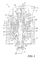
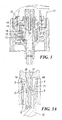
- the pump comprises a cup-shaped body 2 defining a cylindrical chamber 3 into which a hollow stem 4 extends. That stem surface 4A defining the cavity presents a conical lead-in portion 60 in proximity to a first stem end.
- An endpiece 5 is also present mounted on an open first end 2A of the cup-shaped body 2. The endpiece is integral with a ring cap 27 for fixing to a container on which the pump is to be mounted.
- the cup-shaped body presents a passage 6, sealedly closable by a unidirectional valve 7.
- the cup-shaped body also presents a seat 8 for housing one end of a dip tube 9 for withdrawing the fluid substance from the container.
- the passage 6 connects the interior of the cylindrical chamber 3 to the tube 9.
- the pump also comprises a piston 12 sealedly slidable on the inner surface 11 of the cylindrical chamber 3.
- the piston 12 is integral with the stem 4 and is hence rigid therewith.
- the piston is disposed in proximity to a first end 4D of the stem 4 within the chamber 3 and projecting towards the inner surface of the cup-shaped body 3.
- the endpiece 5 presents a hole 13 through which the stem 4 emerges and is guided, and also presents a seal element for the piston.
- This seal element 14 is of ring configuration and presents an annular groove 15 of tapered cross-section into which a corresponding upper (in Figure 2 ) annular portion 16 of the piston 12 is wedged.
- the piston 12 is urged towards the endpiece into its rest position by an elastic member.
- the elastic member is a spring 20, on the second end of the stem there being mounted an operating and dispensing pushbutton 21.
- the spring 20 is positioned between the pushbutton and the endpiece 5 in such a manner as not to be in contact with the fluid dispensed by the pump.
- this spring can be positioned between a groove provided in the cup-shaped body and the piston itself.
- An elongated rod 22, positioned inside the cup-shaped body 2, has its first end 22A inserted into a seat 23 provided at the second end 2B of the cup-shaped body 2 and retained thereat by an undercut fit.
- the seat 23 presents a plurality of fins (not shown) which securely fix the rod 22.
- the rod comprises an intermediate cylindrical profile portion 22C of diameter less than the diameter of the stem cavity into which said rod portion extends.
- the cavity of the stem 4 is in communication with the outside, dispensing of the fluid substance taking place through said cavity.
- a movable valve 25 for closing said cavity is present in the cavity, this valve 25 comprising a continuous elastic lip 26 projecting from a second rod end 22B towards the outside of the cylindrical chamber.
- the lip 26 is of frusto-conical conformation, its shape being such as to create between the lip and the inner surface of the stem a wedge-shaped interstice 270 which tapers away from the cylindrical chamber 3, in the fluid dispensing direction.
- the lip 26 is substantially slidable (with the movement of the piston 12) in contact with and sealing against the cylindrical surface 4A of the cavity in the stem 4.
- the lip 26 defines a recess 30 which, given its shape, contributes to providing the lip 26 with the necessary flexibility and elasticity.
- the profiled element 31 which becomes inserted into the recess 30 when the stem is totally lowered into the pump; the profiled element is substantially complementary to the recess and when inserted into it, it minimizes the space present between the top of the rod and the stem.
- a passage hole 32 is provided axially in the profiled element 31 and is connected to a dispensing hole 33 opening onto the outside of the pushbutton 21.
- the lip flexes to allow fluid dispensing in the direction of the arrows E of Figure 2 .
- the unidirectional valve 7 consists of a flexible discoidal piece 40 projecting from the surface of the rod 22 in proximity to its first end 22A and of a sharp-edged sealing surface 41 provided on the internal second end 2B of the cup-shaped body 2.
- the discoidal piece 40 prevents fluid passage from the chamber 3 to the tube 9 under rest or dispensing conditions.
- the aforedescribed unidirectional valve 7, formed integrally with the rod 22, can be replaced by a conventional unidirectional ball valve commonly used in these types of pump.
- the cup-shaped body 2 presents a housing for the ball and a surface against which it seals, above the ball there being provided the fins which retain the rod.
- the ball is movable in the housing.
- the stem 4 presents a groove 50 provided in the inner surface 40 of the stem cavity. This groove is located in a position such as to cooperate with the projecting lip in such a manner as to open the valve 25 ( Figure 3A ) when the piston 12 is pressed into its end of stroke position, to vent the compressed air in the cylindrical chamber 3 (arrows 5) when the pump is being primed.
- This groove can be replaced by other priming means such as a raised portion projecting into the stem cavity.
- This raised portion must be located in a position such as to interfere with the projecting lip in order to open the valve when the piston is pressed into its end of stroke position.
- the cup-shaped body 2 can also present at its second end, inside the chamber, at least one raised portion arranged to interfere with the slidable piston in such a manner as to open its seal, when the piston is pressed into its end of stroke position.
- Such a pump structure enables a very compact pump to be obtained, in particular of very small internal and external height
Landscapes
- Reciprocating Pumps (AREA)
- Closures For Containers (AREA)
- Extraction Or Liquid Replacement (AREA)
- Jet Pumps And Other Pumps (AREA)
- Details Of Reciprocating Pumps (AREA)
Claims (14)
- Pumpe zum Abgeben flüssiger Substanzen, welche aus einem Behälter der Substanzen entnommen werden, umfassend einen becherförmigen Körper (2), welcher eine zylindrische Kammer (3) definiert, in welche sich ein hohler Schaft (4) erstreckt, ein Endstück (5), welches an einem offenen ersten Ende des becherförmigen Körpers (2) angebracht ist, wobei der becherförmige Körper (2) an seinem zweiten Ende (2B) einen Durchgang, welcher durch ein unidirektionales Ventil (7) dicht verschließbar ist, und einen Sitz (8) zum Unterbringen eines Endes eines Eintauchrohrs (9) zum Entnehmen der flüssigen Substanz aus dem Behälter bietet, einen Kolben (12), welcher entlang der Fläche (11) der zylindrischen Kammer abgedichtet verschiebbar ist, wobei der Kolben starr zu dem Schaft (4) ist und in der Nähe eines ersten Endes des Schaftes innerhalb der Kammer (3) angeordnet ist und in Richtung der Innenfläche des becherförmigen Körpers (2) hervorragt, wobei das Endstück (5) sowohl mit einem Loch, durch welches der Schaft hervortritt und durch welches er geführt wird, als auch mit mindestens einem Element (14), welches in der Ruheposition gegen den Kolben abdichtet, versehen ist, ein elastisches Element (20), welches in dem Sinn eines Drängens des Kolbens (12) in Richtung des Endstücks (5) arbeitet, ein bewegliches Ventil (25) zum Schließen des Hohlraums des Schafts (4), und einen zumindest teilweise in dem Innenraum des becherförmigen Körpers (2) angeordneten länglichen Stab (22), von dem ein erstes Ende (22A) in einen Sitz (23) eingesetzt ist und davon gehalten wird, welcher an dem zweiten Ende des becherförmigen Körpers (2) vorgesehen ist, wobei ein Zwischenabschnitt (22C) des Stabs ein zylindrisches Profil mit einem Durchmesser kleiner als der Durchmesser des Hohlraums des Schafts (4), in welchen sich der Stababschnitt erstreckt, aufweist, wobei das bewegliche Ventil (25) zum Schließen des Hohlraums des Schafts eine durchgängige elastische Lippe (26) umfasst, welche von einem zweiten Ende (22B) des Stabes in Richtung der Außenseite der zylindrischen Kammer hervorragt, wobei sich die Lippe abgedichtet verschiebbar in Kontakt mit der zylindrischen Fläche (4A) des Hohlraums des Schafts befindet, dadurch gekennzeichnet, dass das erste Ende (22A) des länglichen Stabes an dem Sitz (23) durch eine unterschnittene Passung gehalten wird.
- Pumpe nach Anspruch 1, dadurch gekennzeichnet, dass die Lippe (26) einen Hohlraum (30) an dem zweiten Ende (22B) des Stabes definiert.
- Pumpe nach Anspruch 2, dadurch gekennzeichnet, dass von der Oberseite des Schaftes ein profiliertes Element (31), welches in den von der Lippe (26) definierten Hohlraum (30) einsetzbar ist, hervorragt, wenn der Schaft gänzlich in die Pumpe abgesenkt ist, wobei das profilierte Element (31) im Wesentlichen komplementär zu dem Hohlraum ist.
- Pumpe nach Anspruch 1, dadurch gekennzeichnet, dass das unidirektionale Ventil (7) aus einem flexiblen scheibenförmigen Stück (40), welches von der Fläche des Stabes (22) in der Nähe des ersten Endes (22A) hervorragt, und aus einer Dichtfläche (41), welche an dem inneren zweiten Ende des becherförmigen Körpers (2) vorgesehen ist, besteht, wobei das scheibenförmige Stück einen Flüssigdurchgang unter Ruhe- oder Abgabebedingungen verhindert.
- Pumpe nach Anspruch 4, dadurch gekennzeichnet, dass die Dichtfläche (41) scharfkantig ist.
- Pumpe nach Anspruch 1, dadurch gekennzeichnet, dass das unidirektionale Ventil ein Ball ist, welcher zwischen dem becherförmigen Körper und der Unterseite des Stabes angeordnet ist.
- Pumpe nach Anspruch 1, dadurch gekennzeichnet, dass ein Betriebs- und Abgabedruckknopf (21) äußerlich an dem zweiten Ende des Schafts befestigt ist, wobei das elastische Element (20) zwischen dem Druckknopf und dem Endstück angeordnet ist.
- Pumpe nach Anspruch 1, dadurch gekennzeichnet, dass das elastische Element eine Feder ist.
- Pumpe nach Anspruch 1, dadurch gekennzeichnet, dass der Schaft (4) an seinem zweiten Ende mindestens einen angehobenen Abschnitt bietet, welcher in den Innenraum des Schafthohlraums hervorragt, wobei der angehobene Abschnitt in einer Position derart angeordnet ist, dass er eine Auswirkung auf die hervorragende Lippe (26) in einer derartigen Art und Weise aufweist, dass das Ventil geöffnet wird, wenn der Kolben in seine Hubendposition gedrückt wird.
- Pumpe nach Anspruch 1, dadurch gekennzeichnet, dass der Schaft an seinem zweiten Ende eine Nut (50) bietet, welche an der Innenfläche (4A) des Schafthohlraums vorgesehen ist, wobei die Nut in einer Position derart angeordnet ist, dass sie mit der hervorragenden Lippe (26) in einer derartigen Art und Weise zusammenarbeitet, dass das Ventil geöffnet wird, wenn der Kolben in seine Hubendposition gedrückt wird.
- Pumpe nach Anspruch 1, dadurch gekennzeichnet, dass der becherförmige Körper (2) an seinem zweiten Ende in dem Innenraum der Kammer (3) mindestens einen angehobenen Abschnitt bietet, welcher ausgestaltet ist, auf den gleitenden Kolben derart einzuwirken, dass seine Abdichtung unterbrochen wird, wenn der Kolben in seine Hubendposition gedrückt wird.
- Pumpe nach Anspruch 1, dadurch gekennzeichnet, dass das Endstück (5) integriert mit einem Ringaufsatz ausgebildet ist, welcher der Pumpe ermöglicht, an dem Behälter befestigt zu werden.
- Pumpe nach Anspruch 1, dadurch gekennzeichnet, dass das Endstückdichtelement (14) ringförmig ist und als ein Dichtungsanschlag für den Kolben arbeitet, wenn dieser in seiner Ruheposition ist.
- Pumpe nach Anspruch 1, dadurch gekennzeichnet, dass der Schafthohlraum eine konische Einführung (60) in der Nähe seines ersten Endes bietet.
Applications Claiming Priority (1)
| Application Number | Priority Date | Filing Date | Title |
|---|---|---|---|
| IT001266A ITMI20061266A1 (it) | 2006-06-29 | 2006-06-29 | Pompa semplificata di mandata di sostanze fluide prelevate da un contenitore |
Publications (2)
| Publication Number | Publication Date |
|---|---|
| EP1872859A1 EP1872859A1 (de) | 2008-01-02 |
| EP1872859B1 true EP1872859B1 (de) | 2009-11-25 |
Family
ID=38335526
Family Applications (2)
| Application Number | Title | Priority Date | Filing Date |
|---|---|---|---|
| EP07111076A Not-in-force EP1872859B1 (de) | 2006-06-29 | 2007-06-26 | Vereinfachte Pumpe zur Abgabe von aus einem Behälter entnommenen flüssigen Substanzen |
| EP07799176A Withdrawn EP2032269A2 (de) | 2006-06-29 | 2007-06-29 | Pumpen und verfahren zu ihrer verwendung |
Family Applications After (1)
| Application Number | Title | Priority Date | Filing Date |
|---|---|---|---|
| EP07799176A Withdrawn EP2032269A2 (de) | 2006-06-29 | 2007-06-29 | Pumpen und verfahren zu ihrer verwendung |
Country Status (7)
| Country | Link |
|---|---|
| US (2) | US7837070B2 (de) |
| EP (2) | EP1872859B1 (de) |
| AT (1) | ATE449648T1 (de) |
| DE (1) | DE602007003407D1 (de) |
| ES (1) | ES2335704T3 (de) |
| IT (1) | ITMI20061266A1 (de) |
| WO (1) | WO2008003076A2 (de) |
Cited By (1)
| Publication number | Priority date | Publication date | Assignee | Title |
|---|---|---|---|---|
| WO2021187716A1 (ko) * | 2020-03-20 | 2021-09-23 | 주식회사 삼화 | 펌프캡 |
Families Citing this family (14)
| Publication number | Priority date | Publication date | Assignee | Title |
|---|---|---|---|---|
| ITMI20061266A1 (it) * | 2006-06-29 | 2007-12-30 | Microspray Delta Spa | Pompa semplificata di mandata di sostanze fluide prelevate da un contenitore |
| NZ581439A (en) | 2007-05-30 | 2013-03-28 | Fluid dispenser with a piston sealingly movable in a dosing chamber but only in sealing contact with a narrower first section during a part of the stroke. | |
| DE102009022215B4 (de) * | 2009-05-20 | 2011-06-22 | LINDAL Dispenser GmbH, 23923 | Ventil zur dosierten Abgabe von Flüssigkeiten |
| KR101192603B1 (ko) * | 2010-11-22 | 2012-10-26 | (주)연우 | 이종 내용물 혼합용기 |
| DE102011106261A1 (de) * | 2011-05-18 | 2012-11-22 | Meadwestvaco Calmar Gmbh | Spender zur dosierten Abgabe von flüssigen Medien |
| ITVI20130130A1 (it) * | 2013-05-08 | 2014-11-09 | Taplast Srl | Dispositivo per l'erogazione di fluidi. |
| WO2015105716A2 (en) | 2014-01-13 | 2015-07-16 | Meadwestvaco Corporation | Dispensing pump with skirt spring |
| US10335816B1 (en) | 2018-08-29 | 2019-07-02 | Armin Arminak | All plastic water resistant pump |
| CA3025843A1 (en) * | 2018-11-29 | 2020-05-29 | Op-Hygiene Ip Gmbh | Valve retention under pressure |
| GB2587372B (en) * | 2019-09-25 | 2022-09-07 | Berlin Packaging Uk Ltd | Improved fluid dispensers |
| USD991785S1 (en) | 2020-01-31 | 2023-07-11 | Armin Arminak | Lotion pump actuator |
| US11498089B2 (en) | 2021-04-04 | 2022-11-15 | Armin Arminak | All plastic continuous spray trigger sprayer |
| US11389814B1 (en) * | 2021-04-16 | 2022-07-19 | Armin Arminak | All plastic hand pump with a piston having an integrated check valve |
| US11471905B1 (en) | 2021-09-23 | 2022-10-18 | Apackaging Group Llc | All plastic airless pump dispenser |
Family Cites Families (23)
| Publication number | Priority date | Publication date | Assignee | Title |
|---|---|---|---|---|
| DE1259203B (de) | 1963-11-30 | 1968-01-18 | Roder Gottfried | Ventil fuer Kleinpumpen aus Kunststoffteilen |
| US3361078A (en) * | 1965-12-15 | 1968-01-02 | Diamond Int Corp | Liquid dispenser |
| US3583605A (en) * | 1969-01-17 | 1971-06-08 | Diamond Int Corp | Liquid dispensing pump |
| US3907174A (en) * | 1971-04-13 | 1975-09-23 | Vca Corp | Dispensing pump construction with foldable discharge nozzle |
| AU471702B2 (en) | 1973-06-26 | 1976-04-29 | Precision Valve Australia Pty. Limited | Pump |
| US4111367A (en) * | 1977-02-18 | 1978-09-05 | Ethyl Corporation | Finger operated spray pump |
| US4371097A (en) | 1980-05-07 | 1983-02-01 | Diamond International Corporation | Liquid dispensing pump |
| EP0340724A3 (de) | 1988-04-30 | 1990-04-18 | Tubex Vertrieb Gmbh | Spender |
| FR2643338B1 (fr) | 1989-02-21 | 1991-05-10 | Valois | Dispositif distributeur doseur a pompe pour produits fluides |
| JPH0669161U (ja) * | 1993-03-05 | 1994-09-27 | 大和製罐株式会社 | ポンプ式泡出し容器 |
| DE19605153A1 (de) * | 1996-02-13 | 1997-08-14 | Pfeiffer Erich Gmbh & Co Kg | Austragvorrichtung für Medien und Verfahren zur Herstellung einer Austragvorrichtung o. dgl. |
| FR2776633B1 (fr) | 1998-03-26 | 2000-06-09 | Valois Sa | Dispositif de distribution airless |
| US6170713B1 (en) | 1998-10-28 | 2001-01-09 | Emson, Inc. | Double spring precompression pump with priming feature |
| KR200233932Y1 (ko) * | 2001-01-22 | 2001-09-25 | 강성일 | 배출 장치 및 그를 이용한 화장품 용기 |
| EP1266696A1 (de) * | 2001-06-13 | 2002-12-18 | Taplast S.p.A. | Balgpumpe zur Abgabe von Gasflüssigkeitmischungen |
| FR2848617B1 (fr) * | 2002-12-16 | 2006-03-17 | Oreal | Pompe et recipient ainsi equipe |
| US6779689B2 (en) * | 2003-01-21 | 2004-08-24 | Unilever Home & Personal Care Usa, Division Of Conopco, Inc. | Ovaloid dispensing container |
| US7048153B2 (en) * | 2003-09-25 | 2006-05-23 | Unilever Home & Personal Care Usa, Division Of Conopco, Inc. | Foam dispensing article |
| ITMI20032082A1 (it) * | 2003-10-24 | 2005-04-25 | Microspray Delta Spa | Pompa invertibile azionabile a mano per l'erogazione di liquidi atomizzati |
| KR100766816B1 (ko) * | 2006-01-18 | 2007-10-17 | 주식회사 다린 | 내용물 정량 토출과 누액방지 및 변질방지 기능을 갖는에어리스 타입 화장품 용기 |
| ITMI20061266A1 (it) * | 2006-06-29 | 2007-12-30 | Microspray Delta Spa | Pompa semplificata di mandata di sostanze fluide prelevate da un contenitore |
| US7735692B2 (en) * | 2006-10-10 | 2010-06-15 | Meadwestvaco Calmar, Inc. | Rotating dispenser head with locking and venting closure connector for an air foaming pump dispenser |
| US7735688B2 (en) * | 2006-10-10 | 2010-06-15 | Meadwestvaco Calmar, Inc. | Rotating collar and locking and venting closure connector for an air foaming pump dispenser |
-
2006
- 2006-06-29 IT IT001266A patent/ITMI20061266A1/it unknown
-
2007
- 2007-06-19 US US11/765,028 patent/US7837070B2/en not_active Expired - Fee Related
- 2007-06-26 DE DE602007003407T patent/DE602007003407D1/de active Active
- 2007-06-26 ES ES07111076T patent/ES2335704T3/es active Active
- 2007-06-26 AT AT07111076T patent/ATE449648T1/de not_active IP Right Cessation
- 2007-06-26 EP EP07111076A patent/EP1872859B1/de not_active Not-in-force
- 2007-06-29 EP EP07799176A patent/EP2032269A2/de not_active Withdrawn
- 2007-06-29 WO PCT/US2007/072459 patent/WO2008003076A2/en active Application Filing
- 2007-06-29 US US12/306,574 patent/US20100012682A1/en not_active Abandoned
Cited By (1)
| Publication number | Priority date | Publication date | Assignee | Title |
|---|---|---|---|---|
| WO2021187716A1 (ko) * | 2020-03-20 | 2021-09-23 | 주식회사 삼화 | 펌프캡 |
Also Published As
| Publication number | Publication date |
|---|---|
| WO2008003076A2 (en) | 2008-01-03 |
| WO2008003076A3 (en) | 2008-06-05 |
| US7837070B2 (en) | 2010-11-23 |
| ATE449648T1 (de) | 2009-12-15 |
| DE602007003407D1 (de) | 2010-01-07 |
| US20100012682A1 (en) | 2010-01-21 |
| EP1872859A1 (de) | 2008-01-02 |
| ES2335704T3 (es) | 2010-03-31 |
| US20080000933A1 (en) | 2008-01-03 |
| EP2032269A2 (de) | 2009-03-11 |
| ITMI20061266A1 (it) | 2007-12-30 |
Similar Documents
| Publication | Publication Date | Title |
|---|---|---|
| EP1872859B1 (de) | Vereinfachte Pumpe zur Abgabe von aus einem Behälter entnommenen flüssigen Substanzen | |
| US8631976B2 (en) | Manually operated pump comprising an assembly for pressurization and dispensing of fluid | |
| US6168050B1 (en) | Hand-operated pump with a trigger, for dispensing liquids | |
| US10525493B2 (en) | Pump for a receptacle, in particular a bottle for a cosmetic product, and a dispensing device comprising such a pump | |
| EP1565270B1 (de) | Vordruckpumpe mit verringerter höhe | |
| US20070045349A1 (en) | Liquid dispensing pump with shifting liquid piston | |
| KR102161238B1 (ko) | 거품 분배기 | |
| KR20010049439A (ko) | 방아쇠 분사기용 배출 밸브 조립체 | |
| US20060231577A1 (en) | Viscous liquid dispensing pump | |
| US10821456B2 (en) | Device for dispensing a product with improved triggering | |
| EP1525923B1 (de) | Handbetätigbare Pumpe zur Abgabe von zerstäubten Flüssigkeiten in der Überkopfstellung | |
| US3500760A (en) | Pump for an atomizer or the like | |
| US6186368B1 (en) | Manually actuated pump assembly | |
| EP1033174B1 (de) | Handbetätigbare Pumpe zur Ausgabe von Flüssigkeiten unter Druck | |
| US7073690B2 (en) | Invertible pump with air passageways, for dispensing atomized liquids | |
| CN115038650B (zh) | 用于各种包装的抽取流体产品的按压机构 | |
| KR200401893Y1 (ko) | 액체용기용 압출펌프 | |
| KR200281525Y1 (ko) | 화장품용기의 펌핑장치 | |
| EP0484616B1 (de) | Handbetätigte Pumpe für Fluide | |
| KR200295706Y1 (ko) | 디스펜서 | |
| WO2010105641A1 (en) | Dispensing device for a fluid substance enclosed in a container | |
| KR20040047060A (ko) | 화장품용기의 펌프구조 | |
| KR20210129480A (ko) | 에어리스 펌핑형 화장품 용기 |
Legal Events
| Date | Code | Title | Description |
|---|---|---|---|
| PUAI | Public reference made under article 153(3) epc to a published international application that has entered the european phase |
Free format text: ORIGINAL CODE: 0009012 |
|
| AK | Designated contracting states |
Kind code of ref document: A1 Designated state(s): AT BE BG CH CY CZ DE DK EE ES FI FR GB GR HU IE IS IT LI LT LU LV MC MT NL PL PT RO SE SI SK TR |
|
| AX | Request for extension of the european patent |
Extension state: AL BA HR MK YU |
|
| RAP1 | Party data changed (applicant data changed or rights of an application transferred) |
Owner name: MEADWESTVACO CALMAR S.R.L. |
|
| 17P | Request for examination filed |
Effective date: 20080616 |
|
| AKX | Designation fees paid |
Designated state(s): AT BE BG CH CY CZ DE DK EE ES FI FR GB GR HU IE IS IT LI LT LU LV MC MT NL PL PT RO SE SI SK TR |
|
| 17Q | First examination report despatched |
Effective date: 20080902 |
|
| GRAP | Despatch of communication of intention to grant a patent |
Free format text: ORIGINAL CODE: EPIDOSNIGR1 |
|
| GRAS | Grant fee paid |
Free format text: ORIGINAL CODE: EPIDOSNIGR3 |
|
| GRAA | (expected) grant |
Free format text: ORIGINAL CODE: 0009210 |
|
| AK | Designated contracting states |
Kind code of ref document: B1 Designated state(s): AT BE BG CH CY CZ DE DK EE ES FI FR GB GR HU IE IS IT LI LT LU LV MC MT NL PL PT RO SE SI SK TR |
|
| REG | Reference to a national code |
Ref country code: GB Ref legal event code: FG4D |
|
| REG | Reference to a national code |
Ref country code: CH Ref legal event code: EP |
|
| REG | Reference to a national code |
Ref country code: IE Ref legal event code: FG4D |
|
| REF | Corresponds to: |
Ref document number: 602007003407 Country of ref document: DE Date of ref document: 20100107 Kind code of ref document: P |
|
| REG | Reference to a national code |
Ref country code: NL Ref legal event code: VDEP Effective date: 20091125 Ref country code: ES Ref legal event code: FG2A Ref document number: 2335704 Country of ref document: ES Kind code of ref document: T3 |
|
| LTIE | Lt: invalidation of european patent or patent extension |
Effective date: 20091125 |
|
| PG25 | Lapsed in a contracting state [announced via postgrant information from national office to epo] |
Ref country code: PT Free format text: LAPSE BECAUSE OF FAILURE TO SUBMIT A TRANSLATION OF THE DESCRIPTION OR TO PAY THE FEE WITHIN THE PRESCRIBED TIME-LIMIT Effective date: 20100325 Ref country code: LT Free format text: LAPSE BECAUSE OF FAILURE TO SUBMIT A TRANSLATION OF THE DESCRIPTION OR TO PAY THE FEE WITHIN THE PRESCRIBED TIME-LIMIT Effective date: 20091125 Ref country code: IS Free format text: LAPSE BECAUSE OF FAILURE TO SUBMIT A TRANSLATION OF THE DESCRIPTION OR TO PAY THE FEE WITHIN THE PRESCRIBED TIME-LIMIT Effective date: 20100325 Ref country code: FI Free format text: LAPSE BECAUSE OF FAILURE TO SUBMIT A TRANSLATION OF THE DESCRIPTION OR TO PAY THE FEE WITHIN THE PRESCRIBED TIME-LIMIT Effective date: 20091125 Ref country code: SE Free format text: LAPSE BECAUSE OF FAILURE TO SUBMIT A TRANSLATION OF THE DESCRIPTION OR TO PAY THE FEE WITHIN THE PRESCRIBED TIME-LIMIT Effective date: 20091125 |
|
| PG25 | Lapsed in a contracting state [announced via postgrant information from national office to epo] |
Ref country code: SI Free format text: LAPSE BECAUSE OF FAILURE TO SUBMIT A TRANSLATION OF THE DESCRIPTION OR TO PAY THE FEE WITHIN THE PRESCRIBED TIME-LIMIT Effective date: 20091125 Ref country code: PL Free format text: LAPSE BECAUSE OF FAILURE TO SUBMIT A TRANSLATION OF THE DESCRIPTION OR TO PAY THE FEE WITHIN THE PRESCRIBED TIME-LIMIT Effective date: 20091125 Ref country code: LV Free format text: LAPSE BECAUSE OF FAILURE TO SUBMIT A TRANSLATION OF THE DESCRIPTION OR TO PAY THE FEE WITHIN THE PRESCRIBED TIME-LIMIT Effective date: 20091125 Ref country code: CY Free format text: LAPSE BECAUSE OF FAILURE TO SUBMIT A TRANSLATION OF THE DESCRIPTION OR TO PAY THE FEE WITHIN THE PRESCRIBED TIME-LIMIT Effective date: 20091125 |
|
| PG25 | Lapsed in a contracting state [announced via postgrant information from national office to epo] |
Ref country code: AT Free format text: LAPSE BECAUSE OF FAILURE TO SUBMIT A TRANSLATION OF THE DESCRIPTION OR TO PAY THE FEE WITHIN THE PRESCRIBED TIME-LIMIT Effective date: 20091125 Ref country code: BE Free format text: LAPSE BECAUSE OF FAILURE TO SUBMIT A TRANSLATION OF THE DESCRIPTION OR TO PAY THE FEE WITHIN THE PRESCRIBED TIME-LIMIT Effective date: 20091125 |
|
| PG25 | Lapsed in a contracting state [announced via postgrant information from national office to epo] |
Ref country code: NL Free format text: LAPSE BECAUSE OF FAILURE TO SUBMIT A TRANSLATION OF THE DESCRIPTION OR TO PAY THE FEE WITHIN THE PRESCRIBED TIME-LIMIT Effective date: 20091125 Ref country code: DK Free format text: LAPSE BECAUSE OF FAILURE TO SUBMIT A TRANSLATION OF THE DESCRIPTION OR TO PAY THE FEE WITHIN THE PRESCRIBED TIME-LIMIT Effective date: 20091125 Ref country code: RO Free format text: LAPSE BECAUSE OF FAILURE TO SUBMIT A TRANSLATION OF THE DESCRIPTION OR TO PAY THE FEE WITHIN THE PRESCRIBED TIME-LIMIT Effective date: 20091125 Ref country code: BG Free format text: LAPSE BECAUSE OF FAILURE TO SUBMIT A TRANSLATION OF THE DESCRIPTION OR TO PAY THE FEE WITHIN THE PRESCRIBED TIME-LIMIT Effective date: 20100225 Ref country code: EE Free format text: LAPSE BECAUSE OF FAILURE TO SUBMIT A TRANSLATION OF THE DESCRIPTION OR TO PAY THE FEE WITHIN THE PRESCRIBED TIME-LIMIT Effective date: 20091125 |
|
| PG25 | Lapsed in a contracting state [announced via postgrant information from national office to epo] |
Ref country code: CZ Free format text: LAPSE BECAUSE OF FAILURE TO SUBMIT A TRANSLATION OF THE DESCRIPTION OR TO PAY THE FEE WITHIN THE PRESCRIBED TIME-LIMIT Effective date: 20091125 Ref country code: SK Free format text: LAPSE BECAUSE OF FAILURE TO SUBMIT A TRANSLATION OF THE DESCRIPTION OR TO PAY THE FEE WITHIN THE PRESCRIBED TIME-LIMIT Effective date: 20091125 |
|
| PLBE | No opposition filed within time limit |
Free format text: ORIGINAL CODE: 0009261 |
|
| STAA | Information on the status of an ep patent application or granted ep patent |
Free format text: STATUS: NO OPPOSITION FILED WITHIN TIME LIMIT |
|
| PG25 | Lapsed in a contracting state [announced via postgrant information from national office to epo] |
Ref country code: GR Free format text: LAPSE BECAUSE OF FAILURE TO SUBMIT A TRANSLATION OF THE DESCRIPTION OR TO PAY THE FEE WITHIN THE PRESCRIBED TIME-LIMIT Effective date: 20100226 |
|
| 26N | No opposition filed |
Effective date: 20100826 |
|
| PG25 | Lapsed in a contracting state [announced via postgrant information from national office to epo] |
Ref country code: MC Free format text: LAPSE BECAUSE OF NON-PAYMENT OF DUE FEES Effective date: 20100630 |
|
| PG25 | Lapsed in a contracting state [announced via postgrant information from national office to epo] |
Ref country code: IE Free format text: LAPSE BECAUSE OF NON-PAYMENT OF DUE FEES Effective date: 20100626 Ref country code: MT Free format text: LAPSE BECAUSE OF FAILURE TO SUBMIT A TRANSLATION OF THE DESCRIPTION OR TO PAY THE FEE WITHIN THE PRESCRIBED TIME-LIMIT Effective date: 20091125 |
|
| REG | Reference to a national code |
Ref country code: CH Ref legal event code: PL |
|
| PG25 | Lapsed in a contracting state [announced via postgrant information from national office to epo] |
Ref country code: CH Free format text: LAPSE BECAUSE OF NON-PAYMENT OF DUE FEES Effective date: 20110630 Ref country code: LI Free format text: LAPSE BECAUSE OF NON-PAYMENT OF DUE FEES Effective date: 20110630 |
|
| PG25 | Lapsed in a contracting state [announced via postgrant information from national office to epo] |
Ref country code: HU Free format text: LAPSE BECAUSE OF FAILURE TO SUBMIT A TRANSLATION OF THE DESCRIPTION OR TO PAY THE FEE WITHIN THE PRESCRIBED TIME-LIMIT Effective date: 20100526 Ref country code: LU Free format text: LAPSE BECAUSE OF NON-PAYMENT OF DUE FEES Effective date: 20100626 |
|
| PG25 | Lapsed in a contracting state [announced via postgrant information from national office to epo] |
Ref country code: TR Free format text: LAPSE BECAUSE OF FAILURE TO SUBMIT A TRANSLATION OF THE DESCRIPTION OR TO PAY THE FEE WITHIN THE PRESCRIBED TIME-LIMIT Effective date: 20091125 |
|
| REG | Reference to a national code |
Ref country code: FR Ref legal event code: PLFP Year of fee payment: 10 |
|
| REG | Reference to a national code |
Ref country code: FR Ref legal event code: PLFP Year of fee payment: 11 |
|
| PGFP | Annual fee paid to national office [announced via postgrant information from national office to epo] |
Ref country code: IT Payment date: 20170622 Year of fee payment: 11 |
|
| REG | Reference to a national code |
Ref country code: FR Ref legal event code: PLFP Year of fee payment: 12 |
|
| PG25 | Lapsed in a contracting state [announced via postgrant information from national office to epo] |
Ref country code: IT Free format text: LAPSE BECAUSE OF NON-PAYMENT OF DUE FEES Effective date: 20180626 |
|
| PGFP | Annual fee paid to national office [announced via postgrant information from national office to epo] |
Ref country code: FR Payment date: 20210625 Year of fee payment: 15 Ref country code: DE Payment date: 20210629 Year of fee payment: 15 |
|
| PGFP | Annual fee paid to national office [announced via postgrant information from national office to epo] |
Ref country code: GB Payment date: 20210628 Year of fee payment: 15 |
|
| PGFP | Annual fee paid to national office [announced via postgrant information from national office to epo] |
Ref country code: ES Payment date: 20210701 Year of fee payment: 15 |
|
| REG | Reference to a national code |
Ref country code: DE Ref legal event code: R119 Ref document number: 602007003407 Country of ref document: DE |
|
| GBPC | Gb: european patent ceased through non-payment of renewal fee |
Effective date: 20220626 |
|
| PG25 | Lapsed in a contracting state [announced via postgrant information from national office to epo] |
Ref country code: FR Free format text: LAPSE BECAUSE OF NON-PAYMENT OF DUE FEES Effective date: 20220630 |
|
| PG25 | Lapsed in a contracting state [announced via postgrant information from national office to epo] |
Ref country code: GB Free format text: LAPSE BECAUSE OF NON-PAYMENT OF DUE FEES Effective date: 20220626 Ref country code: DE Free format text: LAPSE BECAUSE OF NON-PAYMENT OF DUE FEES Effective date: 20230103 |
|
| REG | Reference to a national code |
Ref country code: ES Ref legal event code: FD2A Effective date: 20230731 |
|
| PG25 | Lapsed in a contracting state [announced via postgrant information from national office to epo] |
Ref country code: ES Free format text: LAPSE BECAUSE OF NON-PAYMENT OF DUE FEES Effective date: 20220627 |