EP0484616B1 - Handbetätigte Pumpe für Fluide - Google Patents
Handbetätigte Pumpe für Fluide Download PDFInfo
- Publication number
- EP0484616B1 EP0484616B1 EP91105908A EP91105908A EP0484616B1 EP 0484616 B1 EP0484616 B1 EP 0484616B1 EP 91105908 A EP91105908 A EP 91105908A EP 91105908 A EP91105908 A EP 91105908A EP 0484616 B1 EP0484616 B1 EP 0484616B1
- Authority
- EP
- European Patent Office
- Prior art keywords
- pump device
- gasket
- delivery
- ball
- during
- Prior art date
- Legal status (The legal status is an assumption and is not a legal conclusion. Google has not performed a legal analysis and makes no representation as to the accuracy of the status listed.)
- Expired - Lifetime
Links
Images
Classifications
-
- B—PERFORMING OPERATIONS; TRANSPORTING
- B05—SPRAYING OR ATOMISING IN GENERAL; APPLYING FLUENT MATERIALS TO SURFACES, IN GENERAL
- B05B—SPRAYING APPARATUS; ATOMISING APPARATUS; NOZZLES
- B05B11/00—Single-unit hand-held apparatus in which flow of contents is produced by the muscular force of the operator at the moment of use
- B05B11/01—Single-unit hand-held apparatus in which flow of contents is produced by the muscular force of the operator at the moment of use characterised by the means producing the flow
- B05B11/10—Pump arrangements for transferring the contents from the container to a pump chamber by a sucking effect and forcing the contents out through the dispensing nozzle
- B05B11/1001—Piston pumps
- B05B11/1004—Piston pumps comprising a movable cylinder and a stationary piston
-
- B—PERFORMING OPERATIONS; TRANSPORTING
- B05—SPRAYING OR ATOMISING IN GENERAL; APPLYING FLUENT MATERIALS TO SURFACES, IN GENERAL
- B05B—SPRAYING APPARATUS; ATOMISING APPARATUS; NOZZLES
- B05B11/00—Single-unit hand-held apparatus in which flow of contents is produced by the muscular force of the operator at the moment of use
- B05B11/01—Single-unit hand-held apparatus in which flow of contents is produced by the muscular force of the operator at the moment of use characterised by the means producing the flow
- B05B11/10—Pump arrangements for transferring the contents from the container to a pump chamber by a sucking effect and forcing the contents out through the dispensing nozzle
- B05B11/1001—Piston pumps
- B05B11/1009—Piston pumps actuated by a lever
- B05B11/1011—Piston pumps actuated by a lever without substantial movement of the nozzle in the direction of the pressure stroke
-
- B—PERFORMING OPERATIONS; TRANSPORTING
- B05—SPRAYING OR ATOMISING IN GENERAL; APPLYING FLUENT MATERIALS TO SURFACES, IN GENERAL
- B05B—SPRAYING APPARATUS; ATOMISING APPARATUS; NOZZLES
- B05B11/00—Single-unit hand-held apparatus in which flow of contents is produced by the muscular force of the operator at the moment of use
- B05B11/01—Single-unit hand-held apparatus in which flow of contents is produced by the muscular force of the operator at the moment of use characterised by the means producing the flow
- B05B11/10—Pump arrangements for transferring the contents from the container to a pump chamber by a sucking effect and forcing the contents out through the dispensing nozzle
- B05B11/1095—Pump arrangements for transferring the contents from the container to a pump chamber by a sucking effect and forcing the contents out through the dispensing nozzle with movable suction side
Definitions
- This invention relates to a manually operated pump device for dispensing fluids from containers, particularly of the portable type for connection to said containers, for example by threaded ring nuts or capsules.
- Fluid dispensing pumps are known, e.g. from EP-A-0 302 994, consisting substantially of a cylinder, a mobile piston operationally connected to a trigger lever, delivery and suction valves, elastic return means and a delivery channel.
- the unidirectional delivery valves provided in known pumps consist of shutoff valves of conventional type housed in convenient seats provided within the device and operated by gravity or by return springs.
- the object of the invention is to provide a manually operated pump device for dispensing fluids which is composed of a small number of relatively simple components which can be obtained by moulding plastics material, and are easily assembled.
- the pump according to the invention comprises a mobile member for pumping the fluid to be dispensed, said mobile member (9) being operationally connected to a trigger lever and cooperating with a fixed guide member, a ball suction valve, elastic return means and a delivery head (6), and is characterised by comprising a delivery valve comprising a gasket sealing against said mobile member and fixed member and acting as a counteracting member for said elastic return means.
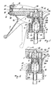
- the first embodiment of the pump device shown in Figure 1 comprises a hollow cylindrical handgrip 1 connected lowerly to a rotatable screw cap 3, a trigger lever 2, a delivery channel 4 and a delivery head 6.
- the lever 2 is pivoted on supports 7 provided on the inner sides of a pair of parallel spaced-apart walls 7A connected to the handgrip 1.
- Said trigger lever also comprises two arms 32 which pass through suitable apertures provided in the cylindrical wall of the handgrip 1 to cooperate with a collar 8 of a mobile cylinder 9 slidingly contained within said handgrip.
- Said cylinder 9 slides along the walls of a fixed piston 10 and contracts lowerly into bottle-neck shape with a frusto-conical part 13 which when the trigger lever 2 is not operated rests on the lower collar of a ring 11.
- the end 12A of the neck engages with a dip-tube 12 which dips into the fluid to be dispensed.
- a suction valve 14 Within the chamber 22 defined by the cylinder 9 and piston 10 there are provided a suction valve 14, a gasket and a loading or return spring 17.
- the suction valve 14 is a conventional ball valve which when in its rest position rests on the frusto-conical part 13 of the cylinder 9, its travel being limited by the turns of the spring 17.
- the gasket 16 is substantially of cap shape comprising a diverging toroidal band 16A in contact with the inner lateral walls of the cylinder 9, a central step 16B externally in contact with the end of the piston 10, an upper step 16C in contact internally with the spring 17 and externally with ribs 24 provided radially on the inner wall of the piston 10, and a terminal conical hollow lip 34 which is thinner than the other portions and is cut radially along a longitudinal part to form a series of petals which when the device is not operated but is in the suction stage adhere to each other to seal the exit passage from the chamber 22.
- the loading spring 17 acts upperly against the gasket step 16C and lowerly against suitable radial ribs 18 provided on the inside of the cylinder 9.
- the delivery head 6 is snap-fitted to an annular portion 26 at the end of the delivery channel 4 of variable inner section, and according to its position it either connects said channel 4, via a groove 32 and a fixed channel 40 in said annular portion 26, to one of the different-shaped orifices 31, 30 and 29, or prevents the fluid from leaving.
- Figure 2 shows a second embodiment of the pump device.
- the cap-shaped gasket 16 terminates with a step 16C with a central hole, on the outside of which there rests a ball 42 restricted in its travel by a step provided on the ribs 43 disposed radially on the inner wall of the piston 10.
- the ball 14 rests by gravity on the conical contraction 13 of the cylinder to hermetically close the passage towards to dip-tube 12.
- the cylinder 9 begins to rise and as its upward travel continues it compresses the fluid in the chamber 22 which, on reaching a certain pressure, diverges the petals of the part 34 of the gasket 16, to then flow into the delivery channel 4 and from here through the delivery head 6 to the outside.
- the operation of the second embodiment of the device differs from the first only in terms of the delivery stage, in that on reaching a given pressure the fluid raises the ball 42, to then flow into the delivery channel 4.
- the ball 42 On completion of delivery the ball 42 returns to rest by gravity on the step 16C to form a seal.
- the travel of the ball 42 is limited upperly by the step 44 provided on the ribs 43.
Claims (4)
- Manuell betriebene Pumpenvorrichtung zum Ausgeben von Flüssigkeiten aus Behältern, insbesondere vom tragbaren Typ zur Verbindung mit den Behältern, insbesondere durch mit Gewinden versehenen Ringmuttern oder Kapseln, mit einem bewegbaren Element (9) zum Pumpen der auszugebenden Flüssigkeit, wobei das bewegbare Element (9) mit einem Auslösehebel (2) in Wirkverbindung steht und mit einem festen Führungsteil (10), einem Kugel-Saugventil, einem elastischen Rückkehrmittel (17) und einem Lieferkopf (6) zusammenwirkt, gekennzeichnet durch ein Lieferventil mit einer Dichtung (16), die gegen das bewegbare Element (9) und das feste Führungsteil (10) abdichtet und als ein gegenwirkendes Element für das elastische Rückkehrmittel wirkt.
- Pumpenvorrichtung nach Anspruch 1, dadurch gekennzeichnet, daß die Dichtung (16) selbst als Ventil wirkt und mit einem Ende (34) versehen ist, das so eingerichtet ist, daß es während des Lieferstadiums auseinandergeht und während des Saugstadiums eine Dichtung formt.
- Pumpenvorrichtung nach Anspruch 1, dadurch gekennzeichnet, daß auf die Dichtung (16) eine Kugel (42) wirkt, die während des Lieferstadiums von einem Loch in der Dichtung hochsteigt und während des Saugstadiums dagegen abdichtet.
- Pumpenvorrichtung nach Anspruch 3, dadurch gekennzeichnet, daß der Bewegungsweg der Kugel (42) nach oben durch Stufen (44) begrenzt ist, die auf an der inneren Oberfläche des festen Teils (10) befindlichen Rippen (42) vorgesehen sind.
Applications Claiming Priority (2)
| Application Number | Priority Date | Filing Date | Title |
|---|---|---|---|
| IT22062U IT220413Z2 (it) | 1990-11-06 | 1990-11-06 | Dispositivo a pompa per dosare o dispensare fluidi azionambile a mano. |
| IT2206290U | 1990-11-06 |
Publications (2)
| Publication Number | Publication Date |
|---|---|
| EP0484616A1 EP0484616A1 (de) | 1992-05-13 |
| EP0484616B1 true EP0484616B1 (de) | 1994-08-03 |
Family
ID=11190910
Family Applications (1)
| Application Number | Title | Priority Date | Filing Date |
|---|---|---|---|
| EP91105908A Expired - Lifetime EP0484616B1 (de) | 1990-11-06 | 1991-04-13 | Handbetätigte Pumpe für Fluide |
Country Status (4)
| Country | Link |
|---|---|
| EP (1) | EP0484616B1 (de) |
| DE (1) | DE69103248T2 (de) |
| ES (1) | ES2058973T3 (de) |
| IT (1) | IT220413Z2 (de) |
Cited By (1)
| Publication number | Priority date | Publication date | Assignee | Title |
|---|---|---|---|---|
| US5816453A (en) * | 1994-03-24 | 1998-10-06 | The English Glass Company Limited | Dispenser pump |
Families Citing this family (2)
| Publication number | Priority date | Publication date | Assignee | Title |
|---|---|---|---|---|
| DE4411031A1 (de) * | 1993-07-22 | 1995-01-26 | Meckenstock Fritz Gmbh | Handhebelbetätigte Pumpe |
| TR202018239A2 (tr) * | 2020-11-14 | 2021-03-22 | Sekeroglu Kimya Ve Plastik Sanayi Ve Ticaret Anonim Sirketi | Sıvı püskürtme başlığı için tek yönlü valf |
Family Cites Families (2)
| Publication number | Priority date | Publication date | Assignee | Title |
|---|---|---|---|---|
| US4527594A (en) * | 1983-06-13 | 1985-07-09 | The Afa Corporation | Check valve |
| JPH0685897B2 (ja) * | 1987-08-11 | 1994-11-02 | 篤 多田 | 手動式トリガ−タイプディスペンサ−およびその生産方法 |
-
1990
- 1990-11-06 IT IT22062U patent/IT220413Z2/it active IP Right Grant
-
1991
- 1991-04-13 DE DE69103248T patent/DE69103248T2/de not_active Expired - Fee Related
- 1991-04-13 ES ES91105908T patent/ES2058973T3/es not_active Expired - Lifetime
- 1991-04-13 EP EP91105908A patent/EP0484616B1/de not_active Expired - Lifetime
Cited By (1)
| Publication number | Priority date | Publication date | Assignee | Title |
|---|---|---|---|---|
| US5816453A (en) * | 1994-03-24 | 1998-10-06 | The English Glass Company Limited | Dispenser pump |
Also Published As
| Publication number | Publication date |
|---|---|
| DE69103248T2 (de) | 1994-11-24 |
| DE69103248D1 (de) | 1994-09-08 |
| IT9022062V0 (it) | 1990-11-06 |
| IT9022062U1 (it) | 1992-05-06 |
| EP0484616A1 (de) | 1992-05-13 |
| ES2058973T3 (es) | 1994-11-01 |
| IT220413Z2 (it) | 1993-09-21 |
Similar Documents
| Publication | Publication Date | Title |
|---|---|---|
| US5289952A (en) | Device for dispensing foam, and push-button for a device of this kind | |
| US4191313A (en) | Trigger operated dispenser with means for obtaining continuous or intermittent discharge | |
| US4618077A (en) | Liquid dispensing pump | |
| EP0179853B1 (de) | Pumpe zur verteilung einer flüssigkeit aus einem behälter | |
| EP1872859B1 (de) | Vereinfachte Pumpe zur Abgabe von aus einem Behälter entnommenen flüssigen Substanzen | |
| EP1399266B9 (de) | Balgpumpe zur abgabe einer gas-flüssigkeitsmischung | |
| EP0755305B1 (de) | Handbetätigte flüssigkeitshubkolbenpumpe | |
| CA2070080C (en) | Liquid pump dispenser having a stationary spout | |
| CZ288430B6 (en) | Precompression pump sprayer | |
| US6168050B1 (en) | Hand-operated pump with a trigger, for dispensing liquids | |
| US5222637A (en) | Manually operated pump device for dispensing fluids | |
| CA1053622A (en) | Manual container mounted pump | |
| US4347953A (en) | Elastomer bulb dispensing pump | |
| EP0145155B1 (de) | Ausgabegerät für ein fliessfähiges Produkt | |
| EP0374348B1 (de) | Vordruckpumpe zur Abgabe von Flüssigkeiten aus einem Behälter | |
| US5850948A (en) | Finger-operable pump with piston biasing post | |
| USRE33235E (en) | Liquid dispensing pump | |
| US20060231577A1 (en) | Viscous liquid dispensing pump | |
| JP2000504618A (ja) | 手動流体分配ポンプ | |
| AU682918B2 (en) | Pump sprayer with stationary discharge | |
| US4215804A (en) | Manual control dispensing pump for liquid containers | |
| US4029261A (en) | Piston displacement liquid spray pumps | |
| US5108013A (en) | Pump for dispensing liquid from a container | |
| US4227628A (en) | Fluid dispensing pump having axially deformable valve | |
| EP0484616B1 (de) | Handbetätigte Pumpe für Fluide |
Legal Events
| Date | Code | Title | Description |
|---|---|---|---|
| PUAI | Public reference made under article 153(3) epc to a published international application that has entered the european phase |
Free format text: ORIGINAL CODE: 0009012 |
|
| AK | Designated contracting states |
Kind code of ref document: A1 Designated state(s): DE ES FR GB IT |
|
| 17P | Request for examination filed |
Effective date: 19920709 |
|
| 17Q | First examination report despatched |
Effective date: 19931217 |
|
| GRAA | (expected) grant |
Free format text: ORIGINAL CODE: 0009210 |
|
| AK | Designated contracting states |
Kind code of ref document: B1 Designated state(s): DE ES FR GB IT |
|
| REF | Corresponds to: |
Ref document number: 69103248 Country of ref document: DE Date of ref document: 19940908 |
|
| ITF | It: translation for a ep patent filed |
Owner name: ING. A. GIAMBROCONO & C. S.R.L. |
|
| ET | Fr: translation filed | ||
| REG | Reference to a national code |
Ref country code: ES Ref legal event code: FG2A Ref document number: 2058973 Country of ref document: ES Kind code of ref document: T3 |
|
| PLBE | No opposition filed within time limit |
Free format text: ORIGINAL CODE: 0009261 |
|
| STAA | Information on the status of an ep patent application or granted ep patent |
Free format text: STATUS: NO OPPOSITION FILED WITHIN TIME LIMIT |
|
| 26N | No opposition filed | ||
| REG | Reference to a national code |
Ref country code: GB Ref legal event code: IF02 |
|
| PGFP | Annual fee paid to national office [announced via postgrant information from national office to epo] |
Ref country code: GB Payment date: 20030409 Year of fee payment: 13 |
|
| PGFP | Annual fee paid to national office [announced via postgrant information from national office to epo] |
Ref country code: ES Payment date: 20030414 Year of fee payment: 13 |
|
| PGFP | Annual fee paid to national office [announced via postgrant information from national office to epo] |
Ref country code: FR Payment date: 20030429 Year of fee payment: 13 |
|
| PGFP | Annual fee paid to national office [announced via postgrant information from national office to epo] |
Ref country code: DE Payment date: 20030620 Year of fee payment: 13 |
|
| PG25 | Lapsed in a contracting state [announced via postgrant information from national office to epo] |
Ref country code: GB Free format text: LAPSE BECAUSE OF NON-PAYMENT OF DUE FEES Effective date: 20040413 |
|
| PG25 | Lapsed in a contracting state [announced via postgrant information from national office to epo] |
Ref country code: ES Free format text: LAPSE BECAUSE OF NON-PAYMENT OF DUE FEES Effective date: 20040414 |
|
| PG25 | Lapsed in a contracting state [announced via postgrant information from national office to epo] |
Ref country code: DE Free format text: LAPSE BECAUSE OF NON-PAYMENT OF DUE FEES Effective date: 20041103 |
|
| GBPC | Gb: european patent ceased through non-payment of renewal fee |
Effective date: 20040413 |
|
| PG25 | Lapsed in a contracting state [announced via postgrant information from national office to epo] |
Ref country code: FR Free format text: LAPSE BECAUSE OF NON-PAYMENT OF DUE FEES Effective date: 20041231 |
|
| REG | Reference to a national code |
Ref country code: FR Ref legal event code: ST |
|
| PG25 | Lapsed in a contracting state [announced via postgrant information from national office to epo] |
Ref country code: IT Free format text: LAPSE BECAUSE OF NON-PAYMENT OF DUE FEES;WARNING: LAPSES OF ITALIAN PATENTS WITH EFFECTIVE DATE BEFORE 2007 MAY HAVE OCCURRED AT ANY TIME BEFORE 2007. THE CORRECT EFFECTIVE DATE MAY BE DIFFERENT FROM THE ONE RECORDED. Effective date: 20050413 |
|
| REG | Reference to a national code |
Ref country code: ES Ref legal event code: FD2A Effective date: 20040414 |