EP1525918B1 - Dispositif d'expérimenter - Google Patents
Dispositif d'expérimenter Download PDFInfo
- Publication number
- EP1525918B1 EP1525918B1 EP04022137A EP04022137A EP1525918B1 EP 1525918 B1 EP1525918 B1 EP 1525918B1 EP 04022137 A EP04022137 A EP 04022137A EP 04022137 A EP04022137 A EP 04022137A EP 1525918 B1 EP1525918 B1 EP 1525918B1
- Authority
- EP
- European Patent Office
- Prior art keywords
- cannulas
- interface
- chamber
- experimentation
- cannula
- Prior art date
- Legal status (The legal status is an assumption and is not a legal conclusion. Google has not performed a legal analysis and makes no representation as to the accuracy of the status listed.)
- Expired - Lifetime
Links
Images


Classifications
-
- G—PHYSICS
- G01—MEASURING; TESTING
- G01N—INVESTIGATING OR ANALYSING MATERIALS BY DETERMINING THEIR CHEMICAL OR PHYSICAL PROPERTIES
- G01N35/00—Automatic analysis not limited to methods or materials provided for in any single one of groups G01N1/00 - G01N33/00; Handling materials therefor
- G01N35/10—Devices for transferring samples or any liquids to, in, or from, the analysis apparatus, e.g. suction devices, injection devices
- G01N35/1079—Devices for transferring samples or any liquids to, in, or from, the analysis apparatus, e.g. suction devices, injection devices with means for piercing stoppers or septums
-
- B—PERFORMING OPERATIONS; TRANSPORTING
- B01—PHYSICAL OR CHEMICAL PROCESSES OR APPARATUS IN GENERAL
- B01L—CHEMICAL OR PHYSICAL LABORATORY APPARATUS FOR GENERAL USE
- B01L3/00—Containers or dishes for laboratory use, e.g. laboratory glassware; Droppers
- B01L3/50—Containers for the purpose of retaining a material to be analysed, e.g. test tubes
- B01L3/502—Containers for the purpose of retaining a material to be analysed, e.g. test tubes with fluid transport, e.g. in multi-compartment structures
- B01L3/5027—Containers for the purpose of retaining a material to be analysed, e.g. test tubes with fluid transport, e.g. in multi-compartment structures by integrated microfluidic structures, i.e. dimensions of channels and chambers are such that surface tension forces are important, e.g. lab-on-a-chip
- B01L3/502715—Containers for the purpose of retaining a material to be analysed, e.g. test tubes with fluid transport, e.g. in multi-compartment structures by integrated microfluidic structures, i.e. dimensions of channels and chambers are such that surface tension forces are important, e.g. lab-on-a-chip characterised by interfacing components, e.g. fluidic, electrical, optical or mechanical interfaces
-
- B—PERFORMING OPERATIONS; TRANSPORTING
- B01—PHYSICAL OR CHEMICAL PROCESSES OR APPARATUS IN GENERAL
- B01L—CHEMICAL OR PHYSICAL LABORATORY APPARATUS FOR GENERAL USE
- B01L3/00—Containers or dishes for laboratory use, e.g. laboratory glassware; Droppers
- B01L3/56—Labware specially adapted for transferring fluids
- B01L3/563—Joints or fittings; Separable fluid transfer means to transfer fluids between at least two containers, e.g. connectors
-
- B—PERFORMING OPERATIONS; TRANSPORTING
- B01—PHYSICAL OR CHEMICAL PROCESSES OR APPARATUS IN GENERAL
- B01L—CHEMICAL OR PHYSICAL LABORATORY APPARATUS FOR GENERAL USE
- B01L2200/00—Solutions for specific problems relating to chemical or physical laboratory apparatus
- B01L2200/02—Adapting objects or devices to another
- B01L2200/026—Fluid interfacing between devices or objects, e.g. connectors, inlet details
-
- B—PERFORMING OPERATIONS; TRANSPORTING
- B01—PHYSICAL OR CHEMICAL PROCESSES OR APPARATUS IN GENERAL
- B01L—CHEMICAL OR PHYSICAL LABORATORY APPARATUS FOR GENERAL USE
- B01L2200/00—Solutions for specific problems relating to chemical or physical laboratory apparatus
- B01L2200/02—Adapting objects or devices to another
- B01L2200/028—Modular arrangements
-
- B—PERFORMING OPERATIONS; TRANSPORTING
- B01—PHYSICAL OR CHEMICAL PROCESSES OR APPARATUS IN GENERAL
- B01L—CHEMICAL OR PHYSICAL LABORATORY APPARATUS FOR GENERAL USE
- B01L2200/00—Solutions for specific problems relating to chemical or physical laboratory apparatus
- B01L2200/04—Exchange or ejection of cartridges, containers or reservoirs
-
- B—PERFORMING OPERATIONS; TRANSPORTING
- B01—PHYSICAL OR CHEMICAL PROCESSES OR APPARATUS IN GENERAL
- B01L—CHEMICAL OR PHYSICAL LABORATORY APPARATUS FOR GENERAL USE
- B01L2300/00—Additional constructional details
- B01L2300/04—Closures and closing means
- B01L2300/041—Connecting closures to device or container
- B01L2300/044—Connecting closures to device or container pierceable, e.g. films, membranes
-
- B—PERFORMING OPERATIONS; TRANSPORTING
- B01—PHYSICAL OR CHEMICAL PROCESSES OR APPARATUS IN GENERAL
- B01L—CHEMICAL OR PHYSICAL LABORATORY APPARATUS FOR GENERAL USE
- B01L2300/00—Additional constructional details
- B01L2300/06—Auxiliary integrated devices, integrated components
- B01L2300/0672—Integrated piercing tool
-
- B—PERFORMING OPERATIONS; TRANSPORTING
- B01—PHYSICAL OR CHEMICAL PROCESSES OR APPARATUS IN GENERAL
- B01L—CHEMICAL OR PHYSICAL LABORATORY APPARATUS FOR GENERAL USE
- B01L2400/00—Moving or stopping fluids
- B01L2400/04—Moving fluids with specific forces or mechanical means
- B01L2400/0475—Moving fluids with specific forces or mechanical means specific mechanical means and fluid pressure
- B01L2400/0487—Moving fluids with specific forces or mechanical means specific mechanical means and fluid pressure fluid pressure, pneumatics
-
- B—PERFORMING OPERATIONS; TRANSPORTING
- B01—PHYSICAL OR CHEMICAL PROCESSES OR APPARATUS IN GENERAL
- B01L—CHEMICAL OR PHYSICAL LABORATORY APPARATUS FOR GENERAL USE
- B01L2400/00—Moving or stopping fluids
- B01L2400/06—Valves, specific forms thereof
- B01L2400/0633—Valves, specific forms thereof with moving parts
-
- B—PERFORMING OPERATIONS; TRANSPORTING
- B01—PHYSICAL OR CHEMICAL PROCESSES OR APPARATUS IN GENERAL
- B01L—CHEMICAL OR PHYSICAL LABORATORY APPARATUS FOR GENERAL USE
- B01L3/00—Containers or dishes for laboratory use, e.g. laboratory glassware; Droppers
- B01L3/50—Containers for the purpose of retaining a material to be analysed, e.g. test tubes
- B01L3/502—Containers for the purpose of retaining a material to be analysed, e.g. test tubes with fluid transport, e.g. in multi-compartment structures
- B01L3/5027—Containers for the purpose of retaining a material to be analysed, e.g. test tubes with fluid transport, e.g. in multi-compartment structures by integrated microfluidic structures, i.e. dimensions of channels and chambers are such that surface tension forces are important, e.g. lab-on-a-chip
- B01L3/50273—Containers for the purpose of retaining a material to be analysed, e.g. test tubes with fluid transport, e.g. in multi-compartment structures by integrated microfluidic structures, i.e. dimensions of channels and chambers are such that surface tension forces are important, e.g. lab-on-a-chip characterised by the means or forces applied to move the fluids
-
- B—PERFORMING OPERATIONS; TRANSPORTING
- B01—PHYSICAL OR CHEMICAL PROCESSES OR APPARATUS IN GENERAL
- B01L—CHEMICAL OR PHYSICAL LABORATORY APPARATUS FOR GENERAL USE
- B01L3/00—Containers or dishes for laboratory use, e.g. laboratory glassware; Droppers
- B01L3/56—Labware specially adapted for transferring fluids
- B01L3/565—Seals
Definitions
- the invention relates to a device for carrying out experiments according to the preamble of patent claim 1.
- connection of the individual containers, in particular of the experimental chamber with the individual containers storing the process materials usually take place with special couplings, which, however, do not adequately prevent leakage of the process substances and thus contamination of the environment, in particular when the containers are replaced.
- a disadvantage of these couplings is that in the case of an exchange of a container or the experimental chamber, process material can escape from the connection lines or external substances or microorganisms can enter, which leads to a contamination of the environment or the experiment.
- the known couplings are commonly used as permanent couplings and not as exchange couplings. This has the further disadvantage that in a running experiment, a container can be replaced only with considerable effort.
- the object of the invention is to provide a compact experimental apparatus for process materials with exchangeable storage containers while maintaining sterility.
- the experimentation chambers have a plurality of openings which are closed with septa. Each opening of the experimental chamber is associated with a cannula.
- means are provided for the relative displacement of the experimental chamber and the cannulas, wherein further cannulas (KK) are present for penetrating a septum (ST) associated with an opening (OG) of a storage container (BA, BB, BC) and wherein an interface (S) is present for establishing a connection between the further cannulas (KK) and the storage containers (BA, BB, BC) as well as between the cannulas (KK) and the experimental chamber (EK, EK1, EK2), wherein the interface (S) a container (K) BA, BB, BC) associated pumping means (P) with an input and output side (ES, AS) for pumping the process material from the container (BA, BB, BC) in the experimental chamber (EK, EK1, EK2).
- the invention is thus that by moving an assembly, such as the experimental chamber with respect to the cannula or vice versa, a temporary or permanent connection between the interior of the experimental chamber and the open end of a cannula can be made. Depending on requirements, it is thus possible to enable or prevent the influx of a process material by means of displacement of an assembly.
- a septum serves to seal the respective opening of the experimental chamber.
- Each septum and thus each opening of the experimental chamber is associated with a cannula according to the invention.
- the open ends introduce cannulas into the septa.
- the storage containers for the process materials are also sealed with septa and associated with other cannulas.
- the storage container can be easily replaced without it comes to an outflow of any existing residual liquid or residual gases from the container.
- the experimental chamber advantageously has a further opening for receiving a sealing body.
- This seal body serves in a first position of the ventilation of the experimental chamber and seals in a second position from the experimental chamber.
- the experimental chamber advantageously has means for venting.
- connection in particular a detachable connection
- the connections between the cannulas and the interface are designed as a hose connection.
- the experimental device has a holding device for releasably receiving the experimentation chamber, the storage container and the cannulas.
- means for producing a bias voltage between the experimental chamber and the holding device are provided. These means are e.g. Feathers.
- the means for relative displacement of the experimental chamber with respect to the cannulas comprises a threaded bore formed in the experimental chamber and a threaded pin provided at the interface for receiving into the threaded bore.
- the transport of the process materials from the storage containers into the experimental chamber takes place according to the invention by means of pumping means.
- a pump in particular a roller pump, is present in the interface.
- the roller pump serves as a valve and the transport of the process materials into the experimental chamber takes place without pressure.
- Fig.1 an exemplary construction of the device is shown, which does not fall under claim 1.
- the storage container BA, BB for the corresponding Process materials connected.
- the container BA, BB are fixed by not shown brackets at the interface S.
- the experiment chamber EK is fastened in a holding device H connected to the interface S.
- the experimentation chamber EK has a threaded bore GB on the side facing the interface S.
- one of the threaded bore GB opposite to the threaded bore GB aligned threaded pin GS is attached.
- This grub screw GB is suitably connected to a transmission / motor unit, not shown.
- a spring F is present.
- This spring F is attached on the one hand to the experimental chamber EK and on the other hand to the interface S. With the spring F, a bias voltage is generated, whereby, for example, when replacing the experimental chamber EK, the threaded bore GB can be reliably placed on the threaded pin GS. This makes it possible that without further intervention from the outside, a relative displacement of the experimental chamber EK can be achieved by operation of the threaded pin GS.
- cannulas K are expediently arranged in parallel with the threaded pin GS in alignment with openings (not shown) made in the experimental chamber EK and closed with septa.
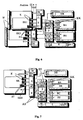
- FIG. 2 schematically a first exemplary embodiment of the device according to the invention in a first operating state 0 is shown.
- This illustration shows the start configuration of an experiment.
- An experiment chamber EK is inserted into the corresponding holder (not shown).
- the threaded bore (not shown) of the experimental chamber EK is fixed on the threaded pin GS of the interface S.
- To drive the threaded pin GS this is connected to a gear / motor unit M.
- the experimental chamber EK has a plurality of openings (not shown), which are closed with septa ST.
- the open ends of the needles K are in this configuration within the septa ST. This is achieved essentially by the fact that by the biasing spring F, the needles K into the septa ST or the experimental chamber EK is brought into this position by the motor-driven threaded pin GS.
- the individual cannulas K are each connected via a pumping arrangement P to a further cannula KK.
- the pumping arrangement P can be suitably connected to an electronic unit E for controlling the pumps.
- These additional needles KK are assigned to the storage containers for the process substances.
- Fig. 2 By way of example, two further needles KK for two storage containers, wherein by way of example only one storage container BA is shown, are shown.
- the storage container BA has an opening (not shown), which is closed with a septum ST.
- the storage container BA is introduced into the holder (not shown) of the interface S such that the further cannula KK completely penetrates the septum ST, whereby the open end of the further cannula KK is located inside the container BA.
- Fig. 3 shows the exemplary arrangement in a second operating state A.
- the experimental chamber EK was moved relative to the needles K by driving the threaded pin GS.
- the experiment chamber EK was moved in the direction of the arrow. It can be seen that a first part of the needles K (the two upper ones) have completely penetrated the septa ST.
- the middle cannula K is connected via the pump assembly P to the reservoir BA. By controlling the corresponding pump, for example via the connected electronics E, process material is transported from the container BA into the experimental chamber EK.
- the upper cannula K is connected to a volume expansion tank DB.
- This volume compensation tank DB serves to compensate for the build-up in the experimentation chamber EK by the filling pressure when using an experimental chamber EK with a rigid wall.
- the pressure building up due to the filling of the experimental chamber EK can also be compensated for by providing a flexible wall for the experimental chamber EK.
- the volume compensation tank DB can thus be omitted.
- a third operating state B of the example arrangement becomes Fig. 2 and 3 shown.
- the experiment chamber EK was in the direction of the arrow shifted, so that in addition to the two upper cannulas K and the lower cannula K completely penetrates the septa ST.
- the lower cannula K is connected via a pump arrangement P with a storage container BB for a process material. By activating the corresponding pump, process material can be conducted from the storage container BB into the experimental chamber EK.
- the experimental chamber EK After completion of the experiment, the experimental chamber EK is moved by means of appropriate rotation of the threaded pin GS opposite to the arrow direction shown. In particular, the experimentation chamber EK is switched to the operating state 0 after completion of an experiment (cf. Fig. 2 ) brought. In this state, the experimental chamber EK and the storage containers BA, BB can be replaced.
- An advantage here is that due to the septa ST no outflow of process material from the experimental chamber EK or from the storage containers BA, BB and no intrusion of external contamination is possible.
- the appropriately designed as a roller pump pumps in the pump assembly P have the advantage that they can be used as a shut-off valve in the off state, ie the pump does not work. This means that even with a pressure difference between the inlet and outlet side of the pump no process material can flow through the pump.
- no process material from the needles K or other needles KK emerge.
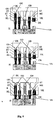
- Fig. 5 are the individual operating states of the Fig. 2-4 shown in detail.
- the upper diagram shows the operating state 0.
- This operating state is the starting state at the beginning of an experiment or after the end of the experiment the state in which the arrangement is brought to exchange the experimental chamber EK or the storage containers (not shown).
- the illustration shows a holding device H attached to the interface (not shown). Attached to this holding device H are the cannulas K, which are encased with sleeves HL.
- a gear / motor unit M is attached to the holding device H, which is connected to a threaded pin GS.
- the holding device H opposite the experimental chamber EK is arranged, which is oriented such that a executed in the experimental chamber EK
- Threaded hole GB is aligned with the set screw GS.
- four openings OG are exemplified in the experimentation chamber EK.
- the openings OG are closed with septa ST.
- the left opening OG is closed with a long septum ST and the second opening OG from the left and the second opening OG from the right with a short septum ST.
- the open ends of the cannulas KK each terminate within the septa ST, ie in this operating state no process material can be conducted from the cannulas KK into the experimental chamber EK.
- a sealing body DK is introduced in the right opening OG .
- the sealing body DK has a channel VK, which extends from the lying in the opening OG end face to a side surface.
- the sealing body DK is introduced into the opening OG in such a way that a ventilation of the experimental chamber EK is possible through the channel VK.
- a membrane ME can be arranged between the interior of the experimental chamber EK and the sealing
- the middle illustration shows the operating state A, in which the experimental chamber has been displaced in the direction of the arrow by corresponding rotation of the threaded pin GS.
- a displacement of the holding device H with respect to a fixed experimental chamber EK is possible.
- the middle and the right septum ST have been completely penetrated by the needles K, so that the open ends of the cannulas K terminate in the experimental chamber EK, whereby an introduction of process material is possible.
- the lower diagram shows the operating state B.
- This operating state B all septa ST are completely penetrated by the respective cannulas K.
- the illustration also shows a stage VS.
- This stage VS is arranged in alignment with the sealing body DK.
- the stage VS pushes the sealing body DK into the opening OG of the experimental chamber EK such that the channel VK ends in the opening OG and thus no ventilation of the experimental chamber EK is possible.
- covers of the cannulas K are designated. These covers are used to release the cannula K when penetrating into the septa ST and to close when removing the needles K from the septa ST.
- FIG. 6 an exemplary second embodiment of the invention is shown.
- a second experimental chamber EK2 is present.
- This second experimental chamber EK2 is connected via its own holding device H to the pumping arrangement P common to the first experimental chamber EK1 and above to the common containers BA, BB.
- two needles KK are provided for each container BA, BB.
- a cannula KK supplies exclusively one experimental chamber EK, the other cannula KK exclusively supplies the other experimental chamber EK2.
- any number of experimentation chambers EK1, EK2 can be provided.
- FIG Fig. 7 A third exemplary embodiment is shown in FIG Fig. 7 shown.
- the output side AS of the pump P which is assigned to the container BB, connected to the input side ES of the container BA associated pump P.
- the process material can be pumped from container BB, for example, into the further cannula KK of the container BA and from there into the experimental chamber EK.
- the output sides AS of two different containers BA, BC associated pump P may be connected to each other and a common further cannula KK fed.
- a further cannula KKS can be attached to the holding device H of the interface S.
- a sample can be drawn from the experimental chamber EK with a corresponding relative position of the experimental chamber EK to the holding device H via a connected pump P.
- This sample is pumped into a, according to the container BA, BB, BC connected sample vessel PS.
- the in Fig. 7 illustrated embodiment to operate with multiple experimentation EK.
Landscapes
- Chemical & Material Sciences (AREA)
- Health & Medical Sciences (AREA)
- General Health & Medical Sciences (AREA)
- Chemical Kinetics & Catalysis (AREA)
- Analytical Chemistry (AREA)
- Clinical Laboratory Science (AREA)
- Dispersion Chemistry (AREA)
- Life Sciences & Earth Sciences (AREA)
- Immunology (AREA)
- Pathology (AREA)
- Physics & Mathematics (AREA)
- Hematology (AREA)
- Biochemistry (AREA)
- General Physics & Mathematics (AREA)
- Sampling And Sample Adjustment (AREA)
- Infusion, Injection, And Reservoir Apparatuses (AREA)
- Investigating Or Analysing Biological Materials (AREA)
- Confectionery (AREA)
- Transition And Organic Metals Composition Catalysts For Addition Polymerization (AREA)
- Devices For Use In Laboratory Experiments (AREA)
Claims (13)
- Dispositif en vue d'exécuter des expériences sur des substances de traitement, comprenant un ou plusieurs récipients (BA, BB, BC) de réserve de substances de traitement et une ou plusieurs chambres d'expérimentation (EK, EK1, EK2) qui reprennent les substances de traitement, les chambres d'expérimentation (EK, EK1, EK2) présentant plusieurs ouvertures (OG) raccordées à des septums (ST),
caractérisé
en ce qu'il présente un septum (ST) par ouverture (OG) de chambre d'expérimentation (EK, EK1, EK2) et une canule (K) par septum (ST),
en ce qu'il présente des moyens (M, GB, GS) permettant le déplacement relatif de la chambre d'expérimentation (EK, EK1, EK2) et des canules (K) et
en ce qu'il présente d'autres canules (KK) destinées à traverser un septum (ST) associé à une ouverture (OG) d'un récipient de réserve (BA, BB, BC),
en ce qu'il présente un moyen de pompe (P) doté d'un côté d'entrée et d'un côté de sortie (ES, AS) et qui pompe la substance de traitement depuis le récipient de réserve (BA, BB, BC) jusque dans la chambre d'expérimentation (EK, EK1, EK2),
en ce que les autres canules (KK) sont reliées au moyen de pompe (P),
en ce qu'une interface (S) est prévue pour établir une liaison entre les autres canules (KK) et les récipients de réserve (BA, BB, BC) ainsi qu'entre les canules (K) et la chambre d'expérimentation (EK, EK1, EK2), l'interface (S) comprenant le moyen de pompe (P),
en ce qu'il présente pour l'interface (S) un support dans lequel les récipients de réserve (BA, BB, BC) sont placés de telle sorte que les autres canules (KK) traversent complètement le septum (ST) de telle sorte que l'extrémité ouverte des autres canules (KK) soit située à l'intérieur du récipient de réserve (BA, BB, BC) et
en ce que la chambre d'expérimentation (EK, EK1, EK2) est fixée dans un dispositif de soutien (H) relié à l'interface (S). - Dispositif selon la revendication 1, caractérisé en ce que la liaison entre l'interface (S), les canules (K) et les autres canules (KK) est réalisée sous la forme de liaisons libérables par tuyau flexible.
- Dispositif selon la revendication 1 ou 2, caractérisé en ce que la chambre d'expérimentation (EK, EK1, EK2) présente une autre ouverture (OG) à laquelle est associé un corps d'étanchéité (DK) qui présente un canal (VK) qui s'étend entre la surface frontale du corps d'étanchéité (DK) tournée vers l'espace intérieur de la chambre d'expérimentation (EK, EK1, EK2) et une surface latérale du corps d'étanchéité (DK).
- Dispositif selon la revendication 3, caractérisé en ce que l'interface (S) présente des moyens (VS) situés face au corps d'étanchéité (DK) pour déplacer le corps d'étanchéité (DK).
- Dispositif selon l'une des revendications 2 à 4, caractérisé en ce que le moyen (M, GB, GS) de déplacement relatif des septums (ST) par rapport à la canule (K) comporte un alésage fileté (GB) ménagé dans la chambre d'expérimentation (EK, EK1, EK2) et une tige filetée (GS) prévue sur l'interface (S) pour être reprise dans l'alésage fileté (GB).
- Dispositif selon la revendication 5, caractérisé en ce qu'il présente des moyens (M) d'entraînement de la tige filetée (GS).
- Dispositif selon l'une des revendications précédentes, caractérisé en ce qu'il présente des moyens (F) qui établissent une précontrainte entre la chambre d'expérimentation (EK, EK1, EK2) et l'interface (S).
- Dispositif selon l'une des revendications précédentes, caractérisé en ce que les canules (K) sont disposées de telle sorte que dans une première position prédéterminée 0, l'ouverture ouverte de toutes les canules (K) est située à l'intérieur de chaque septum (ST), en ce que dans une deuxième position prédéterminée A, pour une première partie des canules (K), l'extrémité ouverte de la canule (K) est située à l'intérieur du septum (ST) concerné et pour une deuxième partie des canules (K), les septums (ST) concernés sont traversés complètement par l'extrémité ouverte des canules (K) et en ce que dans une troisième position prédéterminée B, tous les septums (ST) sont complètement traversés par l'extrémité ouverte des canules (K).
- Dispositif selon l'une des revendications précédentes, caractérisé en ce que le côté de sortie (AS) d'un moyen de pompe (P) est relié à au moins l'une des autres canules (KK).
- Dispositif selon l'une des revendications précédentes, caractérisé en ce que le côté de sortie (AS) de deux moyens de pompe (P) est relié à une autre canule (KK) commune.
- Dispositif selon la revendication 10, caractérisé en ce que le côté de sortie (AS) d'un premier moyen de pompe (P) est relié au côté d'entrée (ES) d'un deuxième moyen de pompe (P).
- Dispositif selon l'une des revendications précédentes, caractérisé en ce qu'il présente des moyens de dégazage de la chambre d'expérimentation (EK, EK1, EK2).
- Dispositif selon l'une des revendications précédentes, caractérisé en ce qu'il présente des couvercles (HL) pour les canules (K).
Applications Claiming Priority (2)
| Application Number | Priority Date | Filing Date | Title |
|---|---|---|---|
| DE10349513 | 2003-10-23 | ||
| DE10349513A DE10349513B4 (de) | 2003-10-23 | 2003-10-23 | Experimentiervorrichtung |
Publications (3)
| Publication Number | Publication Date |
|---|---|
| EP1525918A2 EP1525918A2 (fr) | 2005-04-27 |
| EP1525918A3 EP1525918A3 (fr) | 2005-06-22 |
| EP1525918B1 true EP1525918B1 (fr) | 2011-04-13 |
Family
ID=34384439
Family Applications (1)
| Application Number | Title | Priority Date | Filing Date |
|---|---|---|---|
| EP04022137A Expired - Lifetime EP1525918B1 (fr) | 2003-10-23 | 2004-09-17 | Dispositif d'expérimenter |
Country Status (4)
| Country | Link |
|---|---|
| EP (1) | EP1525918B1 (fr) |
| AT (1) | ATE505268T1 (fr) |
| DE (2) | DE10349513B4 (fr) |
| ES (1) | ES2363338T3 (fr) |
Families Citing this family (9)
| Publication number | Priority date | Publication date | Assignee | Title |
|---|---|---|---|---|
| WO2010007575A2 (fr) * | 2008-07-14 | 2010-01-21 | Koninklijke Philips Electronics N.V. | Dispositif destiné à être utilisé dans des essais de diagnostics moléculaires |
| EP2864503B1 (fr) * | 2012-06-26 | 2019-10-09 | Axxin Pty Ltd | Kit d'amplification et de détection d'acide nucléique |
| US10139322B2 (en) * | 2012-07-03 | 2018-11-27 | Merck Patent Gmbh | Sample preparation device |
| JP6538676B2 (ja) * | 2013-10-28 | 2019-07-03 | ビオカルティ ナームローゼ フェノーツハップBiocartis NV | 生体材料の搬送装置 |
| ES2488365B1 (es) * | 2014-02-07 | 2015-02-10 | Grifols Worldwide Operations Limited | Dispositivo de toma de muestras de contenedores |
| EP2959971A1 (fr) * | 2014-06-27 | 2015-12-30 | Euroimmun Medizinische Labordiagnostika AG | Procédé et dispositif de transfert de liquides |
| US11648179B2 (en) | 2016-05-16 | 2023-05-16 | Haemonetics Corporation | Sealer-less plasma bottle and top for same |
| US11559464B2 (en) | 2016-05-16 | 2023-01-24 | Haemonetics Corporation | Sealer-less plasma bottle and top for same |
| AT520605B1 (de) * | 2017-11-10 | 2020-03-15 | Erba Tech Austria Gmbh | Sensorkassette |
Family Cites Families (8)
| Publication number | Priority date | Publication date | Assignee | Title |
|---|---|---|---|---|
| FR2308932A1 (fr) * | 1975-04-24 | 1976-11-19 | Aquitaine Petrole | Dispositif d'introduction d'echantillons dans un chromatographe |
| DE3817101C2 (de) * | 1988-05-19 | 1998-05-20 | Axel Von Brand | Vorrichtung zum Überleiten von Flüssigkeit von einem Behältnis zu einem anderen Behältnis |
| ES2106198T3 (es) * | 1991-11-01 | 1997-11-01 | Univ Birmingham | Dispositivo de analisis. |
| US5888826A (en) * | 1994-06-30 | 1999-03-30 | Dade Behring Inc. | Combination reagent holding and test device |
| DE29506669U1 (de) * | 1995-04-12 | 1995-06-29 | Schulz, Hans-Joachim, Dr., 10249 Berlin | Laborgerät zur gleichzeitigen, manuellen Durchführung mehrerer chemischer Reaktionen nach einem Stecksystem |
| WO2001021310A2 (fr) * | 1999-09-21 | 2001-03-29 | Genome Therapeutics Corporation | Dispositif de traitement rapide d'echantillons d'adn a manipulation des liquides, thermocyclage, et purification integres |
| DE10149684B4 (de) * | 2001-10-09 | 2005-02-17 | Clondiag Chip Technologies Gmbh | Vorrichtung zur Halterung eines Substanzbibliothekenträgers |
| DE10307227A1 (de) * | 2003-02-14 | 2004-08-26 | Cytocentrics Ccs Gmbh | Verfahren und Vorrichtung zum Kontaktieren einer Mikrofluidstruktur |
-
2003
- 2003-10-23 DE DE10349513A patent/DE10349513B4/de not_active Expired - Fee Related
-
2004
- 2004-09-17 AT AT04022137T patent/ATE505268T1/de active
- 2004-09-17 DE DE502004012393T patent/DE502004012393D1/de not_active Expired - Lifetime
- 2004-09-17 EP EP04022137A patent/EP1525918B1/fr not_active Expired - Lifetime
- 2004-09-17 ES ES04022137T patent/ES2363338T3/es not_active Expired - Lifetime
Also Published As
| Publication number | Publication date |
|---|---|
| EP1525918A2 (fr) | 2005-04-27 |
| DE10349513A1 (de) | 2005-06-02 |
| DE502004012393D1 (de) | 2011-05-26 |
| ATE505268T1 (de) | 2011-04-15 |
| ES2363338T3 (es) | 2011-08-01 |
| DE10349513B4 (de) | 2006-08-31 |
| EP1525918A3 (fr) | 2005-06-22 |
Similar Documents
| Publication | Publication Date | Title |
|---|---|---|
| EP3159021B1 (fr) | Dispositif pour la transplantation de tissu adipeux | |
| DE69310361T2 (de) | Membran-einheit und gebrauchsverfahren für niederdrucktrennung | |
| EP3810747B1 (fr) | Système de traitement modulaire et procédé de montage modulaire d'un système de traitement | |
| DE2655633A1 (de) | Gas/hydraulikdruck-stelltrieb fuer rohrleitungsventile | |
| DE10349513B4 (de) | Experimentiervorrichtung | |
| DE102021129809B3 (de) | Strahlpumpe, Brennstoffzellensystem und Verfahren zum Betrieb eines Brennstoffzellensystems | |
| DE102009001257A1 (de) | Vorrichtung und Verfahren zur Handhabung von Flüssigkeiten | |
| EP1261428B1 (fr) | Distributeur doseur | |
| DE102019100339B4 (de) | Bioprozesstechnische Anlage | |
| EP3998121B1 (fr) | Dispositif de traitement de surface des pièces moulées | |
| EP4089161A1 (fr) | Substrat destiné à l'examen des échantillons et système comprenant le substrat | |
| EP0357998B1 (fr) | Procédé et appareil pour maintenir stérile des prélèvements liquides de fermentateur | |
| EP3624927B1 (fr) | Module de filtration à usage unique ou module de nettoyage à usage unique, pouvant être utilisés respectivement pour un système de filtration modulaire | |
| EP1071960A1 (fr) | Dispositif de dosage et procede permettant de faire fonctionner un dispositif de dosage | |
| DE10341998A1 (de) | Vorrichtung und Verfahren zur Oberflächenbehandlung von Werkstücken in einem Kreislaufsystem | |
| EP4262889B1 (fr) | Dispositif d'irradiation modulaire et procédé d'irradiation | |
| EP3810303A1 (fr) | Système de filtration pour processus biopharmaceutiques | |
| DE3400945A1 (de) | Zentralverriegelungsanlage eines kraftfahrzeugs | |
| DE4335514C2 (de) | Vorrichtung zum Austauschen von Fluids | |
| EP2163892A1 (fr) | Appareil d'analyse de processus | |
| DE69419430T2 (de) | Verfahren und apparat zum wegnehmen von luftschleusen in handbetätigten mikrofiltrationsvorrichtungen | |
| DE102016200960A1 (de) | Pumpvorrichtung | |
| DE2613662C2 (de) | Vorrichtung zur chemisch-mechanischen Reinigung der Getränkeförderleitungen einer Getränkeschankanlage | |
| EP1556647A1 (fr) | Procede et dispositif de prelevement d'echantillons liquides contenus dans des recipients sous pression | |
| DE2659690A1 (de) | Mehrstufige dialyse-apparatur |
Legal Events
| Date | Code | Title | Description |
|---|---|---|---|
| PUAI | Public reference made under article 153(3) epc to a published international application that has entered the european phase |
Free format text: ORIGINAL CODE: 0009012 |
|
| AK | Designated contracting states |
Kind code of ref document: A2 Designated state(s): AT BE BG CH CY CZ DE DK EE ES FI FR GB GR HU IE IT LI LU MC NL PL PT RO SE SI SK TR |
|
| AX | Request for extension of the european patent |
Extension state: AL HR LT LV MK |
|
| PUAL | Search report despatched |
Free format text: ORIGINAL CODE: 0009013 |
|
| AK | Designated contracting states |
Kind code of ref document: A3 Designated state(s): AT BE BG CH CY CZ DE DK EE ES FI FR GB GR HU IE IT LI LU MC NL PL PT RO SE SI SK TR |
|
| AX | Request for extension of the european patent |
Extension state: AL HR LT LV MK |
|
| 17P | Request for examination filed |
Effective date: 20050818 |
|
| AKX | Designation fees paid |
Designated state(s): AT BE BG CH CY CZ DE DK EE ES FI FR GB GR HU IE IT LI LU MC NL PL PT RO SE SI SK TR |
|
| RAP1 | Party data changed (applicant data changed or rights of an application transferred) |
Owner name: EADS ASTRIUM GMBH |
|
| GRAP | Despatch of communication of intention to grant a patent |
Free format text: ORIGINAL CODE: EPIDOSNIGR1 |
|
| GRAS | Grant fee paid |
Free format text: ORIGINAL CODE: EPIDOSNIGR3 |
|
| GRAA | (expected) grant |
Free format text: ORIGINAL CODE: 0009210 |
|
| AK | Designated contracting states |
Kind code of ref document: B1 Designated state(s): AT BE BG CH CY CZ DE DK EE ES FI FR GB GR HU IE IT LI LU MC NL PL PT RO SE SI SK TR |
|
| REG | Reference to a national code |
Ref country code: GB Ref legal event code: FG4D Free format text: NOT ENGLISH |
|
| REG | Reference to a national code |
Ref country code: CH Ref legal event code: EP |
|
| REG | Reference to a national code |
Ref country code: DE Ref legal event code: R081 Ref document number: 502004012393 Country of ref document: DE Owner name: AIRBUS DEFENCE AND SPACE GMBH, DE Free format text: FORMER OWNER: EADS SPACE TRANSPORTATION GMBH, 28199 BREMEN, DE Ref country code: DE Ref legal event code: R081 Ref document number: 502004012393 Country of ref document: DE Owner name: AIRBUS DS GMBH, DE Free format text: FORMER OWNER: EADS SPACE TRANSPORTATION GMBH, 28199 BREMEN, DE |
|
| REG | Reference to a national code |
Ref country code: IE Ref legal event code: FG4D Free format text: LANGUAGE OF EP DOCUMENT: GERMAN |
|
| REF | Corresponds to: |
Ref document number: 502004012393 Country of ref document: DE Date of ref document: 20110526 Kind code of ref document: P |
|
| REG | Reference to a national code |
Ref country code: DE Ref legal event code: R096 Ref document number: 502004012393 Country of ref document: DE Effective date: 20110526 |
|
| REG | Reference to a national code |
Ref country code: NL Ref legal event code: T3 |
|
| REG | Reference to a national code |
Ref country code: ES Ref legal event code: FG2A Ref document number: 2363338 Country of ref document: ES Kind code of ref document: T3 Effective date: 20110801 |
|
| PG25 | Lapsed in a contracting state [announced via postgrant information from national office to epo] |
Ref country code: PT Free format text: LAPSE BECAUSE OF FAILURE TO SUBMIT A TRANSLATION OF THE DESCRIPTION OR TO PAY THE FEE WITHIN THE PRESCRIBED TIME-LIMIT Effective date: 20110816 Ref country code: SE Free format text: LAPSE BECAUSE OF FAILURE TO SUBMIT A TRANSLATION OF THE DESCRIPTION OR TO PAY THE FEE WITHIN THE PRESCRIBED TIME-LIMIT Effective date: 20110413 |
|
| REG | Reference to a national code |
Ref country code: IE Ref legal event code: FD4D |
|
| PG25 | Lapsed in a contracting state [announced via postgrant information from national office to epo] |
Ref country code: GR Free format text: LAPSE BECAUSE OF FAILURE TO SUBMIT A TRANSLATION OF THE DESCRIPTION OR TO PAY THE FEE WITHIN THE PRESCRIBED TIME-LIMIT Effective date: 20110714 Ref country code: SI Free format text: LAPSE BECAUSE OF FAILURE TO SUBMIT A TRANSLATION OF THE DESCRIPTION OR TO PAY THE FEE WITHIN THE PRESCRIBED TIME-LIMIT Effective date: 20110413 Ref country code: FI Free format text: LAPSE BECAUSE OF FAILURE TO SUBMIT A TRANSLATION OF THE DESCRIPTION OR TO PAY THE FEE WITHIN THE PRESCRIBED TIME-LIMIT Effective date: 20110413 Ref country code: CY Free format text: LAPSE BECAUSE OF FAILURE TO SUBMIT A TRANSLATION OF THE DESCRIPTION OR TO PAY THE FEE WITHIN THE PRESCRIBED TIME-LIMIT Effective date: 20110413 |
|
| PG25 | Lapsed in a contracting state [announced via postgrant information from national office to epo] |
Ref country code: IE Free format text: LAPSE BECAUSE OF FAILURE TO SUBMIT A TRANSLATION OF THE DESCRIPTION OR TO PAY THE FEE WITHIN THE PRESCRIBED TIME-LIMIT Effective date: 20110413 Ref country code: EE Free format text: LAPSE BECAUSE OF FAILURE TO SUBMIT A TRANSLATION OF THE DESCRIPTION OR TO PAY THE FEE WITHIN THE PRESCRIBED TIME-LIMIT Effective date: 20110413 Ref country code: CZ Free format text: LAPSE BECAUSE OF FAILURE TO SUBMIT A TRANSLATION OF THE DESCRIPTION OR TO PAY THE FEE WITHIN THE PRESCRIBED TIME-LIMIT Effective date: 20110413 |
|
| PLBE | No opposition filed within time limit |
Free format text: ORIGINAL CODE: 0009261 |
|
| STAA | Information on the status of an ep patent application or granted ep patent |
Free format text: STATUS: NO OPPOSITION FILED WITHIN TIME LIMIT |
|
| PG25 | Lapsed in a contracting state [announced via postgrant information from national office to epo] |
Ref country code: PL Free format text: LAPSE BECAUSE OF FAILURE TO SUBMIT A TRANSLATION OF THE DESCRIPTION OR TO PAY THE FEE WITHIN THE PRESCRIBED TIME-LIMIT Effective date: 20110413 Ref country code: RO Free format text: LAPSE BECAUSE OF FAILURE TO SUBMIT A TRANSLATION OF THE DESCRIPTION OR TO PAY THE FEE WITHIN THE PRESCRIBED TIME-LIMIT Effective date: 20110413 Ref country code: DK Free format text: LAPSE BECAUSE OF FAILURE TO SUBMIT A TRANSLATION OF THE DESCRIPTION OR TO PAY THE FEE WITHIN THE PRESCRIBED TIME-LIMIT Effective date: 20110413 Ref country code: SK Free format text: LAPSE BECAUSE OF FAILURE TO SUBMIT A TRANSLATION OF THE DESCRIPTION OR TO PAY THE FEE WITHIN THE PRESCRIBED TIME-LIMIT Effective date: 20110413 |
|
| 26N | No opposition filed |
Effective date: 20120116 |
|
| PG25 | Lapsed in a contracting state [announced via postgrant information from national office to epo] |
Ref country code: MC Free format text: LAPSE BECAUSE OF NON-PAYMENT OF DUE FEES Effective date: 20110930 |
|
| REG | Reference to a national code |
Ref country code: DE Ref legal event code: R097 Ref document number: 502004012393 Country of ref document: DE Effective date: 20120116 |
|
| GBPC | Gb: european patent ceased through non-payment of renewal fee |
Effective date: 20110917 |
|
| PG25 | Lapsed in a contracting state [announced via postgrant information from national office to epo] |
Ref country code: GB Free format text: LAPSE BECAUSE OF NON-PAYMENT OF DUE FEES Effective date: 20110917 |
|
| REG | Reference to a national code |
Ref country code: AT Ref legal event code: MM01 Ref document number: 505268 Country of ref document: AT Kind code of ref document: T Effective date: 20110917 |
|
| PG25 | Lapsed in a contracting state [announced via postgrant information from national office to epo] |
Ref country code: AT Free format text: LAPSE BECAUSE OF NON-PAYMENT OF DUE FEES Effective date: 20110917 |
|
| PG25 | Lapsed in a contracting state [announced via postgrant information from national office to epo] |
Ref country code: LU Free format text: LAPSE BECAUSE OF NON-PAYMENT OF DUE FEES Effective date: 20110917 |
|
| PG25 | Lapsed in a contracting state [announced via postgrant information from national office to epo] |
Ref country code: BG Free format text: LAPSE BECAUSE OF FAILURE TO SUBMIT A TRANSLATION OF THE DESCRIPTION OR TO PAY THE FEE WITHIN THE PRESCRIBED TIME-LIMIT Effective date: 20110713 |
|
| PG25 | Lapsed in a contracting state [announced via postgrant information from national office to epo] |
Ref country code: TR Free format text: LAPSE BECAUSE OF FAILURE TO SUBMIT A TRANSLATION OF THE DESCRIPTION OR TO PAY THE FEE WITHIN THE PRESCRIBED TIME-LIMIT Effective date: 20110413 |
|
| PG25 | Lapsed in a contracting state [announced via postgrant information from national office to epo] |
Ref country code: HU Free format text: LAPSE BECAUSE OF FAILURE TO SUBMIT A TRANSLATION OF THE DESCRIPTION OR TO PAY THE FEE WITHIN THE PRESCRIBED TIME-LIMIT Effective date: 20110413 |
|
| REG | Reference to a national code |
Ref country code: DE Ref legal event code: R081 Ref document number: 502004012393 Country of ref document: DE Owner name: AIRBUS DEFENCE AND SPACE GMBH, DE Free format text: FORMER OWNER: EADS ASTRIUM GMBH, 85521 OTTOBRUNN, DE Ref country code: DE Ref legal event code: R082 Ref document number: 502004012393 Country of ref document: DE Representative=s name: PATENT- UND RECHTSANWALTSKANZLEI DAUB, DE Ref country code: DE Ref legal event code: R081 Ref document number: 502004012393 Country of ref document: DE Owner name: AIRBUS DS GMBH, DE Free format text: FORMER OWNER: EADS ASTRIUM GMBH, 85521 OTTOBRUNN, DE |
|
| REG | Reference to a national code |
Ref country code: CH Ref legal event code: PFA Owner name: AIRBUS DS GMBH, DE Free format text: FORMER OWNER: EADS ASTRIUM GMBH, DE |
|
| REG | Reference to a national code |
Ref country code: FR Ref legal event code: PLFP Year of fee payment: 12 |
|
| REG | Reference to a national code |
Ref country code: FR Ref legal event code: CA Effective date: 20150916 Ref country code: FR Ref legal event code: CD Owner name: AIRBUS DS GMBH Effective date: 20150916 |
|
| REG | Reference to a national code |
Ref country code: FR Ref legal event code: PLFP Year of fee payment: 13 |
|
| REG | Reference to a national code |
Ref country code: CH Ref legal event code: NV Representative=s name: PATENTANWALTSKANZLEI DAUB, CH |
|
| REG | Reference to a national code |
Ref country code: DE Ref legal event code: R082 Ref document number: 502004012393 Country of ref document: DE Representative=s name: PATENT- UND RECHTSANWALTSKANZLEI DAUB, DE Ref country code: DE Ref legal event code: R081 Ref document number: 502004012393 Country of ref document: DE Owner name: AIRBUS DEFENCE AND SPACE GMBH, DE Free format text: FORMER OWNER: AIRBUS DS GMBH, 82024 TAUFKIRCHEN, DE |
|
| REG | Reference to a national code |
Ref country code: FR Ref legal event code: PLFP Year of fee payment: 14 |
|
| REG | Reference to a national code |
Ref country code: CH Ref legal event code: PFUS Owner name: AIRBUS DEFENCE AND SPACE GMBH, DE Free format text: FORMER OWNER: AIRBUS DS GMBH, DE |
|
| REG | Reference to a national code |
Ref country code: NL Ref legal event code: HC Owner name: AIRBUS DS GMBH; DE Free format text: DETAILS ASSIGNMENT: CHANGE OF OWNER(S), CHANGE OF OWNER(S) NAME; FORMER OWNER NAME: EADS ASTRIUM GMBH Effective date: 20180220 Ref country code: NL Ref legal event code: PD Owner name: AIRBUS DEFENCE AND SPACE GMBH; DE Free format text: DETAILS ASSIGNMENT: CHANGE OF OWNER(S), MERGE; FORMER OWNER NAME: AIRBUS DS GMBH Effective date: 20180220 |
|
| REG | Reference to a national code |
Ref country code: ES Ref legal event code: PC2A Owner name: AIRBUS DEFENCE AND SPACE GMBH Effective date: 20180528 Ref country code: ES Ref legal event code: PC2A Effective date: 20180528 |
|
| REG | Reference to a national code |
Ref country code: BE Ref legal event code: HC Owner name: AIRBUS DS GMBH; DE Free format text: DETAILS ASSIGNMENT: CHANGE OF OWNER(S), CHANGEMENT NOM PROPRIETAIRE; FORMER OWNER NAME: ASTRIUM GMBH Effective date: 20150616 Ref country code: BE Ref legal event code: PD Owner name: AIRBUS DEFENCE AND SPACE GMBH; DE Free format text: DETAILS ASSIGNMENT: CHANGE OF OWNER(S), FUSION; FORMER OWNER NAME: AIRBUS DS GMBH Effective date: 20180413 |
|
| REG | Reference to a national code |
Ref country code: FR Ref legal event code: PLFP Year of fee payment: 15 |
|
| REG | Reference to a national code |
Ref country code: CH Ref legal event code: PCAR Free format text: NEW ADDRESS: LEUTSCHENBACHSTRASSE 95, 8050 ZUERICH (CH) |
|
| PGFP | Annual fee paid to national office [announced via postgrant information from national office to epo] |
Ref country code: ES Payment date: 20191022 Year of fee payment: 16 |
|
| PGFP | Annual fee paid to national office [announced via postgrant information from national office to epo] |
Ref country code: DE Payment date: 20200925 Year of fee payment: 17 Ref country code: NL Payment date: 20200925 Year of fee payment: 17 Ref country code: FR Payment date: 20200914 Year of fee payment: 17 |
|
| PGFP | Annual fee paid to national office [announced via postgrant information from national office to epo] |
Ref country code: IT Payment date: 20200922 Year of fee payment: 17 Ref country code: CH Payment date: 20200921 Year of fee payment: 17 Ref country code: BE Payment date: 20200925 Year of fee payment: 17 |
|
| REG | Reference to a national code |
Ref country code: ES Ref legal event code: FD2A Effective date: 20220117 |
|
| REG | Reference to a national code |
Ref country code: DE Ref legal event code: R119 Ref document number: 502004012393 Country of ref document: DE |
|
| REG | Reference to a national code |
Ref country code: NL Ref legal event code: MM Effective date: 20211001 |
|
| REG | Reference to a national code |
Ref country code: CH Ref legal event code: PL |
|
| REG | Reference to a national code |
Ref country code: BE Ref legal event code: MM Effective date: 20210930 |
|
| PG25 | Lapsed in a contracting state [announced via postgrant information from national office to epo] |
Ref country code: ES Free format text: LAPSE BECAUSE OF NON-PAYMENT OF DUE FEES Effective date: 20200918 |
|
| PG25 | Lapsed in a contracting state [announced via postgrant information from national office to epo] |
Ref country code: NL Free format text: LAPSE BECAUSE OF NON-PAYMENT OF DUE FEES Effective date: 20211001 |
|
| PG25 | Lapsed in a contracting state [announced via postgrant information from national office to epo] |
Ref country code: FR Free format text: LAPSE BECAUSE OF NON-PAYMENT OF DUE FEES Effective date: 20210930 Ref country code: DE Free format text: LAPSE BECAUSE OF NON-PAYMENT OF DUE FEES Effective date: 20220401 Ref country code: BE Free format text: LAPSE BECAUSE OF NON-PAYMENT OF DUE FEES Effective date: 20210930 |
|
| PG25 | Lapsed in a contracting state [announced via postgrant information from national office to epo] |
Ref country code: LI Free format text: LAPSE BECAUSE OF NON-PAYMENT OF DUE FEES Effective date: 20210930 Ref country code: CH Free format text: LAPSE BECAUSE OF NON-PAYMENT OF DUE FEES Effective date: 20210930 |
|
| PG25 | Lapsed in a contracting state [announced via postgrant information from national office to epo] |
Ref country code: IT Free format text: LAPSE BECAUSE OF NON-PAYMENT OF DUE FEES Effective date: 20210917 |