EP1525628B1 - Actionneur piezo-electrique pour des milieux s'ecoulant autour de lui et utilisation d'un tel actionneur piezo-electrique - Google Patents
Actionneur piezo-electrique pour des milieux s'ecoulant autour de lui et utilisation d'un tel actionneur piezo-electrique Download PDFInfo
- Publication number
- EP1525628B1 EP1525628B1 EP03762483A EP03762483A EP1525628B1 EP 1525628 B1 EP1525628 B1 EP 1525628B1 EP 03762483 A EP03762483 A EP 03762483A EP 03762483 A EP03762483 A EP 03762483A EP 1525628 B1 EP1525628 B1 EP 1525628B1
- Authority
- EP
- European Patent Office
- Prior art keywords
- actuator
- piezo stack
- housing shell
- housing
- piezoelectric actuator
- Prior art date
- Legal status (The legal status is an assumption and is not a legal conclusion. Google has not performed a legal analysis and makes no representation as to the accuracy of the status listed.)
- Expired - Lifetime
Links
Images



Classifications
-
- F—MECHANICAL ENGINEERING; LIGHTING; HEATING; WEAPONS; BLASTING
- F16—ENGINEERING ELEMENTS AND UNITS; GENERAL MEASURES FOR PRODUCING AND MAINTAINING EFFECTIVE FUNCTIONING OF MACHINES OR INSTALLATIONS; THERMAL INSULATION IN GENERAL
- F16K—VALVES; TAPS; COCKS; ACTUATING-FLOATS; DEVICES FOR VENTING OR AERATING
- F16K31/00—Actuating devices; Operating means; Releasing devices
- F16K31/004—Actuating devices; Operating means; Releasing devices actuated by piezoelectric means
- F16K31/007—Piezoelectric stacks
-
- H—ELECTRICITY
- H10—SEMICONDUCTOR DEVICES; ELECTRIC SOLID-STATE DEVICES NOT OTHERWISE PROVIDED FOR
- H10N—ELECTRIC SOLID-STATE DEVICES NOT OTHERWISE PROVIDED FOR
- H10N30/00—Piezoelectric or electrostrictive devices
- H10N30/80—Constructional details
- H10N30/88—Mounts; Supports; Enclosures; Casings
-
- H—ELECTRICITY
- H10—SEMICONDUCTOR DEVICES; ELECTRIC SOLID-STATE DEVICES NOT OTHERWISE PROVIDED FOR
- H10N—ELECTRIC SOLID-STATE DEVICES NOT OTHERWISE PROVIDED FOR
- H10N30/00—Piezoelectric or electrostrictive devices
- H10N30/80—Constructional details
- H10N30/88—Mounts; Supports; Enclosures; Casings
- H10N30/883—Additional insulation means preventing electrical, physical or chemical damage, e.g. protective coatings
Definitions
- the invention relates to a piezoelectric actuator for circulating media according to the preamble of claim 1, as it is apparent, for example, from the generic US 4,553,059 A1 as well as uses of the same.
- a piezoelectric actuator for circulating media has inter alia a piezo stack, which is arranged with direct contact at least partially within a variable-shape insulation compound.
- the insulating compound is in turn encompassed by a fluidically sealed actuator housing, which is formed by a housing shell and an associated dimensionally stable actuator cover and likewise dimensionally stable actuator base.
- the actuator cover or the actuator base are arranged on the active main surfaces of the piezo stack, wherein the electrical connection lines of the piezo stack over or with the aid of the actuator cover and / or the actuator bottom are guided out of the actuator housing to the outside.
- the housing shell is made of a limp and / or elastic material and at least largely resistant to the medium flowing around it, in particular fuel. Furthermore, the housing shell has at all points a distance from the piezo stack, wherein the measured along the surface line shell length of the housing shell corresponds to at least the maximum extent of the piezo stack and / or the housing shell is correspondingly stretchable. In more meaningful Way, the material of the housing shell is further electrically neutral.
- the internal volume of the actuator housing is at least largely filled with an insulating compound, for which purpose the housing jacket and the actuator base and the actuator cover are sealingly connected to one another with respect to the insulating compound and the medium flowing around. Furthermore, the insulation material is an electrically insulating fluid and / or a gel whose thermal conductivity is equal to or greater than that of the material of the piezoelectric stack.
- DE 198 18 068 A1 discloses a piezoelectric actuator for flow-around media, which has a piezo stack, which is arranged within a variable-shape insulation mass of an elastic plastic with direct contact to this.
- the insulation compound is in turn encompassed by an actuator housing.
- the actuator housing is formed by a housing jacket, which is connected at its one end with a dimensionally stable actuator cover and at its other end with a dimensionally stable actuator base.
- the actuator cover or the actuator base are connected to the active main surfaces of the piezo stack.
- the electrical connection lines of the piezo stack are led through the actuator cover. Furthermore, it is conceivable to bring the electrical connections of the piezo stack up to the end plates (actuator cover or actuator base) of the actuator and to use one or both end plates as electrical contact surfaces.
- the electrically insulating insulation mass is formed from an elastic plastic, for example silicone, which bears directly against the outer surface of the piezo stack, it must follow the very rapid movement of the piezo stack in use. As a result, there is a risk of cracking in the insulating compound and the detachment of insulating material, so that the flowing medium can reach the piezo stack in a destructive manner.
- an elastic plastic for example silicone
- the object of the invention is to increase the service life of such actuators for circulating media.
- the object is achieved with an actuator having the features of claim 1.
- the hermetic separation layer is shifted away from the highly active surface of the piezo stack.
- u.a. the signs of wear between the particular piezoelectric ceramic having piezo stack and the insulating mass at least reduced.
- An inventive actuator thus allows a free change in length of the actuator, respectively the piezo stack, wherein a wetting probability of the piezo stack with a particular aggressive flowing around medium, preferably a pressurized fuel, at least reduced.
- the housing shell has a distance from the piezo stack at all points. Further, the measured along the surface line shell length of the housing shell corresponds to at least the maximum extent of the actuator and / or the housing shell is at least correspondingly stretchable, so that the expansion of the piezo stack can be perceived by the housing shell.
- the insulating material is largely formed from an incompressible medium, its change in shape, for example, the formation of a waist in the expansion of the piezo stack, to be considered in the dimensioning of the length of the housing shell, in particular in the direction of expansion of the piezo stack.
- an electrically insulating fluid in particular a liquid, and / or a gel is introduced between the housing shell and the piezo stack as insulation mass, the insulation mass, in particular a silicone oil, at least largely filling the internal volume of the actuator housing.
- the internal volume of the actuator housing is at least largely free of a compressible gas.
- the thermal conductivity of the insulating material is preferably equal to or greater than that of the material of the piezo stack.
- the media flowing around the actuator in particular fuel for the operation of an internal combustion engine, can be chemically or otherwise aggressive in nature, a material which is at least largely resistant to the stresses expected from the latter is expediently selected as the material of the housing jacket.
- the viscosity of the insulating medium corresponds approximately to that of the circulating medium, since thereby the Strain on the material of the housing shell on the part of the circulating medium is further reduced.
- actuators when using actuators whose end plate (s) are used as electrical contacts, it is in the material of the housing shell in a meaningful manner to an electrically insulating material.
- the actuator cover with respect to the actuator base with a different cross-sectional area.
- the actuator cover and / or the actuator base has a cross-sectional area which is adapted to the respective conditions of use.
- a preferred use of actuators according to the invention is in and / or as an injection valve, in particular an internal combustion engine, preferably in a gasoline or diesel engine. Furthermore, such an actuator can also be used for a proportional valve and / or for a sonotrode.
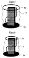
- FIG. 1 shows an exploded view of an actuator according to the invention.
- the actuator has in its interior a centrally arranged piezo stack 1 comprising a plurality of layers of piezo foils made of a piezoelectric ceramic.
- the piezo stack 1 is surrounded by an electrically insulating insulating compound 3, in particular a silicone oil.
- the insulation compound 3 is surrounded on the outside by a housing jacket 4, which is tightly sealed against the insulation compound 3.
- a dimensionally stable actuator cover 5b and, on the other hand, a dimensionally stable actuator base 5a are preferably arranged equidistant from each other.
- the actuator base 5a and the actuator cover 5b are both with respect to the insulation material 3 and with respect to the flowing around Medium sealingly connected to the housing shell 4.
- Actuator bottom 5a, actuator cover 5b and housing shell 4 together form an at least relative to the insulating material 3 and the medium flowing around the actuator housing.
- connection line 2 To the actuator cover 5b electrical connection line 2 are guided, both of which are electrically conductively connected to areas of the actuator cover 5b, but still mutually insulating.
- one of the connection lines 2 is connected to gleichpoligen areas of the piezoelectric films. They serve to supply voltage and to control the expansion of the piezo stack 1. In this way, the corresponding associated with these leads 2 areas of the actuator cover 5b contact surfaces for the electrical control of the actuator.
- the housing shell 4 consists in the present embodiment of a lobed, preferably tear-resistant material. It has a not necessarily constant distance from the piezo stack 1 at all points.
- the actuator of Figure 1 in a flowing around and under pressure (see arrows) fuel for internal combustion engines, preferably gasoline or diesel engines, shown.
- the housing shell 4 made of limp material is of irregular and axial (along the main expansion direction of the piezo stack 1) and radially pushed together or - depressed form (see Figure 2).
- the housing jacket 4 is stretched and approaches a straight course.
- the minimum height of the housing shell 4 measured along the surface line corresponds at least to the corresponding maximum extent of the actuator.
- the called minimum height also includes a compensation of a change in shape of the insulation mass 3, as they can at least occur in an expansion of the piezo stack.
- the change in shape of the liquid and / or gel-like insulating compound 3, preferably a silicone oil, is based on the incompressibility of liquids. Since the volume of an incompressible insulating compound 3 remains the same when the piezo stack 1 expands, its shape must change. This can be done, for example, as shown in FIG. 7, from cylindrical to cylindrical waisted.
- the minimum length of the shell is usually slightly larger than the distance between the two end plates 5 at completely expanded piezo stack 1 (see Figure 2 and 3).
- the compensation should be taken into account in a purely limp and inelastic material already in the length measurement for the housing shell.
- the compensation length and / or the stroke of the piezo stack 1 can be applied in particular solely by the elasticity of the material.
- Figure 4 is similar in many parts to that of the previous figures. However, the illustration is shown without actuator cover 5b and without insulation liquid. In this embodiment, however, the control lines 7 are guided by the - not shown - actuator cover 5b through directly and electrically isolated from each other to the outside.
- one connecting line is electrically conductively connected to the actuator base 5a and the other to the actuator cover 5b.
- the housing shell 4 is made of an electrically insulating material.
- actuators are shown, the actuator base 5a and actuator cover 5b a different cross-section exhibit.
- the end plates serve as electrical connections for the piezo stack 1.
- the housing shell 4 is made of a material which is electrically insulating and elastic. In the relaxed state (voltage equal to zero) of the piezo stack 1, the shell length of the housing shell is greater than the distance between the two sealingly connected with them end plates 5, so that the housing shell awakens a lobed impression.
- the compensation length is applied by the relation to the contracted position of the piezo stack 1 larger shell length and by the elasticity of the material of the housing shell 4.
Landscapes
- Engineering & Computer Science (AREA)
- General Engineering & Computer Science (AREA)
- Mechanical Engineering (AREA)
- Fuel-Injection Apparatus (AREA)
- General Electrical Machinery Utilizing Piezoelectricity, Electrostriction Or Magnetostriction (AREA)
Claims (10)
- Actionneur piézo-électrique pour fluides circulant autour, avec une pile piézo-électrique (1), qui est disposée avec un contact direct au moins par endroits à l'intérieur d'une masse d'isolation (3) variable en forme, qui pour sa part est entourée par un boîtier d'actionneur fermé de façon fluidique, qui est formé par une enveloppe de boîtier (4) et un couvercle d'actionneur (5b) indéformable et relié à l'enveloppe et également par un fond d'actionneur (5a) indéformable et relié au couvercle, le couvercle d'actionneur et le fond d'actionneur étant disposés sur les surfaces principales actives de la pile piézo-électrique, et sur lequel actionneur les conduites de branchements électriques de la pile piézo-électrique sont guidées à partir du boîtier d'actionneur vers l'extérieur en ayant recours au couvercle d'actionneur et/ou au fond d'actionneur,
l'enveloppe de boîtier étant fabriquée à partir d'un matériau flasque et/ou élastique,
le matériau de l'enveloppe de boîtier étant au moins largement résistant vis-à-vis du fluide qui l'entoure, en particulier du carburant,
l'enveloppe du boîtier présentant en tous points une distance à la pile piézo-électrique,
la longueur d'enveloppe, mesurée le long de la ligne d'enveloppe, de l'enveloppe de boîtier correspondant au moins à l'extension maximale de la pile piézo-électrique et/ou l'enveloppe de boîtier étant extensible de façon appropriée,
le matériau de l'enveloppe de boîtier étant électro-isolant,
le volume intérieur du boîtier d'actionneur étant rempli au moins largement avec la masse d'isolation,
l'enveloppe de boîtier et le fond d'actionneur et le couvercle d'actionneur étant reliés de façon étanche entre eux vis à vis de la masse d'isolation et du fluide enveloppant,
la masse d'isolation étant un fluide électro-isolant et/ou un gel, et
la conductibilité thermique de la masse d'isolation étant égale ou supérieure à celle du matériau de la pile piézo-électrique,
caractérisé en ce que
le volume intérieur du boîtier d'actionneur est au moins largement exempt de gaz et
en ce que la viscosité du fluide d'isolation (3) correspond à peu près à celle du fluide enveloppant. - Actionneur piézo-électrique selon la revendication 1, caractérisé en ce que la pile piézo-électrique (3) présente de la céramique piézo-électrique.
- Actionneur piézo-électrique selon la revendication 1, caractérisé en ce que le couvercle d'actionneur (5a) et le fond d'actionneur (5b) étant équidistants l'un de l'autre.
- Actionneur piézo-électrique selon la revendication 1, caractérisé en ce que le couvercle d'actionneur (5a) et le fond d'actionneur (5b) présentent une surface de section différente.
- Actionneur piézo-électrique selon la revendication 1, caractérisé en ce que la masse d'isolation (3) est une huile de silicone.
- Actionneur piézo-électrique selon la revendication 1, caractérisé en ce que le couvercle d'actionneur (5a) et/ou le fond d'actionneur (5b) présentent une surface de section qui correspond respectivement à la surface active, attribuée et disposée transversalement à la direction d'extension principale de la pile piézo-électrique (1), de la pile piézo-électrique (1).
- Actionneur piézo-électrique selon la revendication 1, caractérisé en ce que, le fond d'actionneur (5a) et/ou le couvercle d'actionneur (5b) présente au moins deux zones de terminaison isolées électriquement l'une de l'autre pour les lignes de raccordement (2) électriques de la pile piézo-électrique (1).
- Utilisation d'un actionneur piézo-électrique selon la revendication 1 pour une vanne d'injection, en particulier d'un moteur à combustion interne, de préférence un moteur à allumage commandé ou un moteur diesel.
- Utilisation d'un actionneur piézo-électrique selon la revendication 1 pour une vanne proportionnelle.
- Utilisation d'un actionneur piézo-électrique selon la revendication 1 pour une sonotrode.
Applications Claiming Priority (3)
| Application Number | Priority Date | Filing Date | Title |
|---|---|---|---|
| DE10230032A DE10230032A1 (de) | 2002-07-04 | 2002-07-04 | Piezoelektrischer Aktor für umströmende Medien sowie Verwendung eines entsprechenden piezoelektrischen Aktors |
| DE10230032 | 2002-07-04 | ||
| PCT/EP2003/005964 WO2004006348A2 (fr) | 2002-07-04 | 2003-06-06 | Actionneur piezo-electrique pour des milieux s'ecoulant autour de lui et utilisation d'un tel actionneur piezo-electrique |
Publications (2)
| Publication Number | Publication Date |
|---|---|
| EP1525628A2 EP1525628A2 (fr) | 2005-04-27 |
| EP1525628B1 true EP1525628B1 (fr) | 2007-05-30 |
Family
ID=29761610
Family Applications (1)
| Application Number | Title | Priority Date | Filing Date |
|---|---|---|---|
| EP03762483A Expired - Lifetime EP1525628B1 (fr) | 2002-07-04 | 2003-06-06 | Actionneur piezo-electrique pour des milieux s'ecoulant autour de lui et utilisation d'un tel actionneur piezo-electrique |
Country Status (5)
| Country | Link |
|---|---|
| US (1) | US7250709B2 (fr) |
| EP (1) | EP1525628B1 (fr) |
| JP (1) | JP4157524B2 (fr) |
| DE (2) | DE10230032A1 (fr) |
| WO (1) | WO2004006348A2 (fr) |
Families Citing this family (19)
| Publication number | Priority date | Publication date | Assignee | Title |
|---|---|---|---|---|
| US20060232166A1 (en) * | 2005-04-13 | 2006-10-19 | Par Technologies Llc | Stacked piezoelectric diaphragm members |
| EP1788232A1 (fr) | 2005-11-16 | 2007-05-23 | Siemens Aktiengesellschaft | Dispositif d'actuateur et injecteur de fluide |
| DE102006006889A1 (de) * | 2006-02-15 | 2007-08-23 | Robert Bosch Gmbh | Brennstoffeinspritzventil |
| DE102007011315A1 (de) * | 2006-04-21 | 2007-10-25 | Robert Bosch Gmbh | Piezoaktormodul mit einer Ummantelung und ein Verfahren zu dessen Herstellung |
| DE102006025820A1 (de) | 2006-04-28 | 2007-10-31 | Daimlerchrysler Ag | Piezoelektrischer Aktor mit einer Ummantelung aus einem Verbundwerkstoff |
| DE502006002004D1 (de) * | 2006-05-08 | 2008-12-18 | Continental Automotive Gmbh | Piezo-Aktor, Verfahren zum Herstellen eines Piezo-Aktors und Einspritzsystem mit einem solchen |
| DE102007018039A1 (de) | 2006-09-14 | 2008-03-27 | Robert Bosch Gmbh | Piezoaktormodul mit einem ummantelten Piezoaktor |
| DE102006045663A1 (de) | 2006-09-27 | 2008-04-03 | Robert Bosch Gmbh | Piezoaktor mit einer Ummantelung, zur Anordnung in einem Piezoinjektor |
| DE102006047607A1 (de) * | 2006-10-09 | 2008-04-10 | Robert Bosch Gmbh | Aktormodul mit einem umhüllten Piezoaktor |
| DE102006047606A1 (de) * | 2006-10-09 | 2008-04-10 | Robert Bosch Gmbh | Aktormodul mit einem umhüllten Piezoaktor |
| DE102006051328A1 (de) | 2006-10-31 | 2008-05-08 | Robert Bosch Gmbh | Piezoaktormodul oder Piezoaktor mit einem ummantelnden Schutzschichtsystem |
| DE102006051325A1 (de) | 2006-10-31 | 2008-05-08 | Robert Bosch Gmbh | Anordnung eines Piezoaktors in einer Hülse eines Piezoaktormoduls |
| DE102007004559B4 (de) | 2007-01-30 | 2020-02-27 | Robert Bosch Gmbh | Piezoaktormodul oder Piezoaktor mit einem ummantelnden Schutzschichtsystem und Verfahren zur Herstellung eines solchen Schutzschichtsystems |
| DE102007004552A1 (de) | 2007-01-30 | 2008-07-31 | Robert Bosch Gmbh | Verfahren zur Herstellung eines Piezoaktormoduls mit einem Schutzschichtsystem |
| DE102007040509A1 (de) | 2007-08-28 | 2009-03-05 | Robert Bosch Gmbh | Piezoaktormodul mit einer Umhüllung des Piezoaktors und ein Verfahren zu dessen Herstellung |
| DE102007053303A1 (de) * | 2007-11-08 | 2009-05-14 | Robert Bosch Gmbh | Piezoaktor und Piezoaktormodul mit einem Schutzschichtsystem |
| DE102007056553A1 (de) | 2007-11-23 | 2009-05-28 | Robert Bosch Gmbh | Verfahren zur Herstellung eines Piezoaktormoduls mit einer Umhüllung und ein so hergestelltes Piezoaktormodul |
| US8517284B2 (en) * | 2009-05-13 | 2013-08-27 | Caterpillar Inc. | System and method for internal cooling of a fuel injector |
| US9590164B2 (en) * | 2013-05-03 | 2017-03-07 | Parker-Hannifin Corporation | Encapsulated piezoelectric valve |
Family Cites Families (11)
| Publication number | Priority date | Publication date | Assignee | Title |
|---|---|---|---|---|
| JPS60104762A (ja) * | 1983-11-10 | 1985-06-10 | Nippon Soken Inc | 電歪式アクチュエータ及びそれを用いた燃料噴射弁 |
| US5113108A (en) * | 1988-11-04 | 1992-05-12 | Nec Corporation | Hermetically sealed electrostrictive actuator |
| DE3932966C1 (fr) * | 1989-10-03 | 1991-04-04 | Richard Wolf Gmbh, 7134 Knittlingen, De | |
| JP2508321B2 (ja) * | 1989-12-04 | 1996-06-19 | 日本電気株式会社 | 圧電アクチュエ―タおよびその製造方法 |
| JP2699619B2 (ja) * | 1990-06-27 | 1998-01-19 | 日本電気株式会社 | 電歪効果素子 |
| DE19642653C5 (de) | 1996-10-16 | 2008-02-21 | Daimler Ag | Verfahren zur Bildung eines zündfähigen Kraftstoff/Luft-Gemisches |
| DE19818068A1 (de) | 1998-04-22 | 1999-10-28 | Siemens Ag | Piezoelektronischer Aktor für einen Stellantrieb |
| DE19856186A1 (de) * | 1998-12-05 | 2000-06-15 | Bosch Gmbh Robert | Piezoelektrischer Aktor |
| DE19856185A1 (de) * | 1998-12-05 | 2000-06-15 | Bosch Gmbh Robert | Piezoelektrischer Antrieb |
| DE19857247C1 (de) * | 1998-12-11 | 2000-01-27 | Bosch Gmbh Robert | Piezoelektrischer Aktor |
| DE19914411A1 (de) * | 1999-03-30 | 2000-10-12 | Bosch Gmbh Robert | Piezoelektrischer Aktor |
-
2002
- 2002-07-04 DE DE10230032A patent/DE10230032A1/de not_active Withdrawn
-
2003
- 2003-06-06 DE DE50307380T patent/DE50307380D1/de not_active Expired - Lifetime
- 2003-06-06 EP EP03762483A patent/EP1525628B1/fr not_active Expired - Lifetime
- 2003-06-06 JP JP2004518515A patent/JP4157524B2/ja not_active Expired - Fee Related
- 2003-06-06 WO PCT/EP2003/005964 patent/WO2004006348A2/fr not_active Ceased
- 2003-06-06 US US10/520,172 patent/US7250709B2/en not_active Expired - Fee Related
Non-Patent Citations (1)
| Title |
|---|
| None * |
Also Published As
| Publication number | Publication date |
|---|---|
| JP4157524B2 (ja) | 2008-10-01 |
| US20060087202A1 (en) | 2006-04-27 |
| JP2005532024A (ja) | 2005-10-20 |
| DE50307380D1 (de) | 2007-07-12 |
| WO2004006348A2 (fr) | 2004-01-15 |
| WO2004006348A3 (fr) | 2004-05-13 |
| US7250709B2 (en) | 2007-07-31 |
| EP1525628A2 (fr) | 2005-04-27 |
| DE10230032A1 (de) | 2004-01-22 |
Similar Documents
| Publication | Publication Date | Title |
|---|---|---|
| EP1525628B1 (fr) | Actionneur piezo-electrique pour des milieux s'ecoulant autour de lui et utilisation d'un tel actionneur piezo-electrique | |
| DE3037078C2 (de) | Elektrisch angesteuertes Stellglied | |
| EP1497553B1 (fr) | Dispositif de dosage pour fluides, notamment soupape d'injection d'automobile | |
| DE4306073C1 (de) | Zumeßvorrichtung für Fluide | |
| DE4143343C2 (de) | Mikrominiaturisierte, elektrostatisch betriebene Mikromembranpumpe | |
| EP1290363B1 (fr) | Dispositif d'etancheification | |
| EP0129020B1 (fr) | Dispositif de commande piézoélectrique destiné à une installation d'injection de combustible | |
| DE102006006077B4 (de) | Piezokeramischer Vielschicht-Aktor, Verfahren zum Herstellen eines piezokeramischen Vielschicht-Aktors und Einspritzsystem | |
| DE19914411A1 (de) | Piezoelektrischer Aktor | |
| EP1079158A2 (fr) | Dispositif et procédé de dosage | |
| EP1421271B1 (fr) | Soupape d'injection de carburant | |
| DE10254450A1 (de) | Piezoelektrische Vorrichtung der Stapelart, Verfahren zum Herstellen derselben und Einspritzeinrichtung | |
| AT504485A4 (de) | Piezoelektrischer drucksensor | |
| EP1431568B1 (fr) | Soupape d'injection de carburant | |
| WO2009059864A1 (fr) | Module actionneur piézoélectrique | |
| EP1854996B1 (fr) | Actionneur piézo-électrique, procédé de fabrication d'un actionneur piézo-électrique et système d'injection comportant cet actionneur piézo-électrique | |
| WO2007141133A2 (fr) | Actionneur piézoélectrique | |
| DE102011105756A1 (de) | Elektrische Messeinrichtung zur Kraft- und/oder Druckmessung | |
| DE102006025177A1 (de) | Piezoaktor mit Verkapselung | |
| EP1488096B1 (fr) | Soupape d'injection de carburant | |
| DE102005042759A1 (de) | Piezoelektrischer Aktor | |
| EP1672255B1 (fr) | Joint et région frontière | |
| DE10123174B4 (de) | Ventil zum Steuern von Flüssigkeiten | |
| DE102006006076B4 (de) | Piezo-Aktor, Verfahren zum Herstellen eines Piezo-Aktors und Einspritzsystem mit einem solchen | |
| DE01973531T1 (de) | Verfahren und vorrichtung zur verbesserten schwingungsisolierung |
Legal Events
| Date | Code | Title | Description |
|---|---|---|---|
| PUAI | Public reference made under article 153(3) epc to a published international application that has entered the european phase |
Free format text: ORIGINAL CODE: 0009012 |
|
| 17P | Request for examination filed |
Effective date: 20041221 |
|
| AK | Designated contracting states |
Kind code of ref document: A2 Designated state(s): AT BE BG CH CY CZ DE DK EE ES FI FR GB GR HU IE IT LI LU MC NL PT RO SE SI SK TR |
|
| 17Q | First examination report despatched |
Effective date: 20050629 |
|
| RBV | Designated contracting states (corrected) |
Designated state(s): DE FR GB SE |
|
| GRAP | Despatch of communication of intention to grant a patent |
Free format text: ORIGINAL CODE: EPIDOSNIGR1 |
|
| RIN1 | Information on inventor provided before grant (corrected) |
Inventor name: FLAEMIG-VETTER, TOBIAS Inventor name: OEING, HEINZ Inventor name: RENNER, GREGOR |
|
| RAP1 | Party data changed (applicant data changed or rights of an application transferred) |
Owner name: DAIMLERCHRYSLER AG |
|
| GRAS | Grant fee paid |
Free format text: ORIGINAL CODE: EPIDOSNIGR3 |
|
| GRAA | (expected) grant |
Free format text: ORIGINAL CODE: 0009210 |
|
| AK | Designated contracting states |
Kind code of ref document: B1 Designated state(s): DE FR GB SE |
|
| REG | Reference to a national code |
Ref country code: GB Ref legal event code: FG4D Free format text: NOT ENGLISH |
|
| REF | Corresponds to: |
Ref document number: 50307380 Country of ref document: DE Date of ref document: 20070712 Kind code of ref document: P |
|
| GBT | Gb: translation of ep patent filed (gb section 77(6)(a)/1977) |
Effective date: 20070711 |
|
| PG25 | Lapsed in a contracting state [announced via postgrant information from national office to epo] |
Ref country code: SE Free format text: LAPSE BECAUSE OF FAILURE TO SUBMIT A TRANSLATION OF THE DESCRIPTION OR TO PAY THE FEE WITHIN THE PRESCRIBED TIME-LIMIT Effective date: 20070830 |
|
| ET | Fr: translation filed | ||
| RAP2 | Party data changed (patent owner data changed or rights of a patent transferred) |
Owner name: DAIMLER AG |
|
| PLBE | No opposition filed within time limit |
Free format text: ORIGINAL CODE: 0009261 |
|
| STAA | Information on the status of an ep patent application or granted ep patent |
Free format text: STATUS: NO OPPOSITION FILED WITHIN TIME LIMIT |
|
| 26N | No opposition filed |
Effective date: 20080303 |
|
| REG | Reference to a national code |
Ref country code: FR Ref legal event code: CD |
|
| PGFP | Annual fee paid to national office [announced via postgrant information from national office to epo] |
Ref country code: GB Payment date: 20110630 Year of fee payment: 9 |
|
| PGFP | Annual fee paid to national office [announced via postgrant information from national office to epo] |
Ref country code: FR Payment date: 20110722 Year of fee payment: 9 |
|
| GBPC | Gb: european patent ceased through non-payment of renewal fee |
Effective date: 20120606 |
|
| REG | Reference to a national code |
Ref country code: FR Ref legal event code: ST Effective date: 20130228 |
|
| PG25 | Lapsed in a contracting state [announced via postgrant information from national office to epo] |
Ref country code: FR Free format text: LAPSE BECAUSE OF NON-PAYMENT OF DUE FEES Effective date: 20120702 Ref country code: GB Free format text: LAPSE BECAUSE OF NON-PAYMENT OF DUE FEES Effective date: 20120606 |
|
| PGFP | Annual fee paid to national office [announced via postgrant information from national office to epo] |
Ref country code: DE Payment date: 20151230 Year of fee payment: 13 |
|
| REG | Reference to a national code |
Ref country code: DE Ref legal event code: R119 Ref document number: 50307380 Country of ref document: DE |
|
| PG25 | Lapsed in a contracting state [announced via postgrant information from national office to epo] |
Ref country code: DE Free format text: LAPSE BECAUSE OF NON-PAYMENT OF DUE FEES Effective date: 20170103 |