EP1525384B1 - Carter-cylindres coule sous pression - Google Patents
Carter-cylindres coule sous pression Download PDFInfo
- Publication number
- EP1525384B1 EP1525384B1 EP03764931A EP03764931A EP1525384B1 EP 1525384 B1 EP1525384 B1 EP 1525384B1 EP 03764931 A EP03764931 A EP 03764931A EP 03764931 A EP03764931 A EP 03764931A EP 1525384 B1 EP1525384 B1 EP 1525384B1
- Authority
- EP
- European Patent Office
- Prior art keywords
- cylinder
- cast
- row
- casting
- liner
- Prior art date
- Legal status (The legal status is an assumption and is not a legal conclusion. Google has not performed a legal analysis and makes no representation as to the accuracy of the status listed.)
- Expired - Fee Related
Links
Images

Classifications
-
- F—MECHANICAL ENGINEERING; LIGHTING; HEATING; WEAPONS; BLASTING
- F02—COMBUSTION ENGINES; HOT-GAS OR COMBUSTION-PRODUCT ENGINE PLANTS
- F02F—CYLINDERS, PISTONS OR CASINGS, FOR COMBUSTION ENGINES; ARRANGEMENTS OF SEALINGS IN COMBUSTION ENGINES
- F02F7/00—Casings, e.g. crankcases or frames
- F02F7/0002—Cylinder arrangements
- F02F7/0007—Crankcases of engines with cylinders in line
-
- F—MECHANICAL ENGINEERING; LIGHTING; HEATING; WEAPONS; BLASTING
- F02—COMBUSTION ENGINES; HOT-GAS OR COMBUSTION-PRODUCT ENGINE PLANTS
- F02F—CYLINDERS, PISTONS OR CASINGS, FOR COMBUSTION ENGINES; ARRANGEMENTS OF SEALINGS IN COMBUSTION ENGINES
- F02F1/00—Cylinders; Cylinder heads
- F02F1/02—Cylinders; Cylinder heads having cooling means
- F02F1/10—Cylinders; Cylinder heads having cooling means for liquid cooling
- F02F1/108—Siamese-type cylinders, i.e. cylinders cast together
-
- F—MECHANICAL ENGINEERING; LIGHTING; HEATING; WEAPONS; BLASTING
- F02—COMBUSTION ENGINES; HOT-GAS OR COMBUSTION-PRODUCT ENGINE PLANTS
- F02F—CYLINDERS, PISTONS OR CASINGS, FOR COMBUSTION ENGINES; ARRANGEMENTS OF SEALINGS IN COMBUSTION ENGINES
- F02F1/00—Cylinders; Cylinder heads
- F02F1/02—Cylinders; Cylinder heads having cooling means
- F02F1/10—Cylinders; Cylinder heads having cooling means for liquid cooling
- F02F2001/106—Cylinders; Cylinder heads having cooling means for liquid cooling using a closed deck, i.e. the water jacket is not open at the block top face
-
- F—MECHANICAL ENGINEERING; LIGHTING; HEATING; WEAPONS; BLASTING
- F02—COMBUSTION ENGINES; HOT-GAS OR COMBUSTION-PRODUCT ENGINE PLANTS
- F02F—CYLINDERS, PISTONS OR CASINGS, FOR COMBUSTION ENGINES; ARRANGEMENTS OF SEALINGS IN COMBUSTION ENGINES
- F02F7/00—Casings, e.g. crankcases or frames
- F02F7/0085—Materials for constructing engines or their parts
- F02F2007/009—Hypereutectic aluminum, e.g. aluminum alloys with high SI content
-
- F—MECHANICAL ENGINEERING; LIGHTING; HEATING; WEAPONS; BLASTING
- F05—INDEXING SCHEMES RELATING TO ENGINES OR PUMPS IN VARIOUS SUBCLASSES OF CLASSES F01-F04
- F05C—INDEXING SCHEME RELATING TO MATERIALS, MATERIAL PROPERTIES OR MATERIAL CHARACTERISTICS FOR MACHINES, ENGINES OR PUMPS OTHER THAN NON-POSITIVE-DISPLACEMENT MACHINES OR ENGINES
- F05C2201/00—Metals
- F05C2201/02—Light metals
- F05C2201/021—Aluminium
-
- F—MECHANICAL ENGINEERING; LIGHTING; HEATING; WEAPONS; BLASTING
- F05—INDEXING SCHEMES RELATING TO ENGINES OR PUMPS IN VARIOUS SUBCLASSES OF CLASSES F01-F04
- F05C—INDEXING SCHEME RELATING TO MATERIALS, MATERIAL PROPERTIES OR MATERIAL CHARACTERISTICS FOR MACHINES, ENGINES OR PUMPS OTHER THAN NON-POSITIVE-DISPLACEMENT MACHINES OR ENGINES
- F05C2201/00—Metals
- F05C2201/04—Heavy metals
- F05C2201/0433—Iron group; Ferrous alloys, e.g. steel
- F05C2201/0436—Iron
-
- F—MECHANICAL ENGINEERING; LIGHTING; HEATING; WEAPONS; BLASTING
- F05—INDEXING SCHEMES RELATING TO ENGINES OR PUMPS IN VARIOUS SUBCLASSES OF CLASSES F01-F04
- F05C—INDEXING SCHEME RELATING TO MATERIALS, MATERIAL PROPERTIES OR MATERIAL CHARACTERISTICS FOR MACHINES, ENGINES OR PUMPS OTHER THAN NON-POSITIVE-DISPLACEMENT MACHINES OR ENGINES
- F05C2203/00—Non-metallic inorganic materials
- F05C2203/06—Silicon
-
- Y—GENERAL TAGGING OF NEW TECHNOLOGICAL DEVELOPMENTS; GENERAL TAGGING OF CROSS-SECTIONAL TECHNOLOGIES SPANNING OVER SEVERAL SECTIONS OF THE IPC; TECHNICAL SUBJECTS COVERED BY FORMER USPC CROSS-REFERENCE ART COLLECTIONS [XRACs] AND DIGESTS
- Y10—TECHNICAL SUBJECTS COVERED BY FORMER USPC
- Y10T—TECHNICAL SUBJECTS COVERED BY FORMER US CLASSIFICATION
- Y10T29/00—Metal working
- Y10T29/49—Method of mechanical manufacture
- Y10T29/49229—Prime mover or fluid pump making
- Y10T29/4927—Cylinder, cylinder head or engine valve sleeve making
Definitions
- the invention relates to a die-cast cylinder crankcase according to the preamble of claim 1, and to a method for producing a die-cast cylinder crankcase according to claim 5.
- cylinder crankcases of large series engines are preferably produced for reasons of economy in die-cast aluminum.
- cylinder liners are usually inserted into the tool and cast around. The distances between the cylinder liners are sometimes reduced to less than 3 mm. Narrower webs reduce the stiffness of the cylinder crankcase.
- the US 4,446,906 describes a method for manufacturing a cylinder crankcase using salt cores.
- complex cooling channels can be designed, but the process reliability has proved in a large component such as the cylinder crankcase not suitable for mass production.
- the object of the invention is to provide a die-cast cylinder crankcase and a method for its production, which has over the prior art with a small web width between the cylinder liners improved rigidity and more effective cooling.
- the object is achieved in a die-cast cylinder crankcase according to claim 1, and in a method for producing a die-cast cylinder crankcase according to claim 5.
- the die-cast cylinder crankcase according to the invention according to claim 1 is characterized in that it comprises a series of cylinder liners cast together.
- a series of cylinder liners is referred to in the jargon as a liner, which is why this term is also used in the following.
- the liner is cast in the cylinder crankcase.
- the cylinder crankcase basically from all alloys suitable for this purpose, in particular aluminum alloys but also magnesium alloys can exist.
- the liner is cast in sand casting or chill casting and therefore has the advantage that cavities or undercuts can be displayed comparatively easily. Therefore, the liner has an at least partially closed water jacket with different cooling channels. In particular, the water jacket is at least partially closed in the direction of a cylinder head side of the cylinder crankcase. This leads to a mounting surface of the cylinder head to a larger sealing surface and a better seal between the cylinder head and cylinder crankcase.
- Another advantage of the cylinder crankcase according to the invention is that the webs between the cylinder liners can be provided with cooling channels.
- the distances between them are only between 3 mm and 4 mm.
- the milling or drilling of cooling channels in the land areas between cylinder liners is complex and expensive. Cooling channels in the web areas can already be integrated when using the liners according to the invention.
- the liner can be made of any castable material that meets the tribological and thermal requirements for cylinder treads.
- the liners are preferably made of a gray cast iron material gasoline engines for weight reasons usually a liner of a hypereutectic aluminum-silicon alloy or ordinary aluminum casting alloys (standard alloys) is used.
- the liner is represented in place of a hypereutectic AlSi alloy by a standard aluminum based casting alloy.
- Die-cast components have lower porosity or sand casting components.
- the lower porosity facilitates the application of a tribologically stable layer, preferably a thermal sprayed layer and improves its adhesion.
- the sprayed layer serves as wear protection layer and cylinder running surface.
- a further component of the invention is a method for producing a cylinder crankcase according to claim 5, comprising the following method steps:
- a liner is produced by a casting method known per se (sand casting or chill casting). The casting is done using a lost core, which serves to form cooling channels. The liner has an at least partially closed water jacket.
- the liner is then inserted into a die casting tool.
- the holes of the individual cylinder liners of the liner are placed on sleeves in the die-casting tool and thus fixed.
- the die casting tool is also poured out by a known die casting process. During die casting, the pouring of the liner takes place in the cylinder crankcase, at least partially resulting in a connection of the two metal alloys (liner and cylinder crankcase).
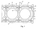
- FIG. 1 starting from a cylinder head side 18 (see FIG. 2), a plan view of a cylinder crankcase 2 with a liner 4 cast in according to the invention is shown.
- the liner 4 comprises a plurality of cylinder liners 5, which are separated from each other by web portions 12 and are limited by the cylinder surfaces 15.
- the cylinder liners 5 of the liner 4 are cast together in a casting process.
- a water jacket 6 is cast in the outer region 9 of the liner 4, a water jacket 6 is cast.
- the water jacket 6 comprises a plurality of mostly interconnected cooling channels 8, 10.
- the water jacket 6 of the liner 4 is connected by transfer openings 13 with a water jacket 14 (FIG. 2) of the cylinder crankcase 2 and with a water jacket of a cylinder head (not shown).
- the outer cooling channels 8 run, as shown in phantom in FIG. 1, at least partially closed in the liner 4.
- the course of cooling channels 10 in the web region 12 is also shown in dashed lines.
- Bolt holes 16 are used to attach the cylinder head.
- Fig. 3 is a longitudinal section through a cylinder crankcase 2 with liner 4 is shown. In this view are in the Web area 12, the cooling channels 10 highlighted. These also run largely closed and, as shown in phantom in Fig. 1, connected to the cooling channels 8.
- the method for producing the cylinder crankcase 2 according to the invention is explained in detail. It will provide a mold with an integrated sand core.
- the mold has the contour of the liner 4, the sand core forms the later water jacket 6.
- the core may have a minimum width of 1.5 mm.
- a hypereutectic aluminum-silicon alloy such as AlSi15, AlSi17 or AlSi9 is poured into the mold.
- the liner 4 is removed from the mold, the sand core removed and the liner 4 optionally deburred and / or machined.
- a surface treatment of the liner 4 can optionally take place, which can improve the connection to the cylinder crankcase 2. This may include mechanical roughening, such as sandblasting, chemical treatments, or coatings.
- the liner 4 is placed in a die-casting tool on sleeves.
- a very accurate centering of the bushes 5 is possible, resulting in a more accurate bore spacing in the cylinder crankcase 2.
- the cylinder crankcase 2 is now in the die-casting with a suitable aluminum alloy, for. B. a AlSi9Cu3 poured.
- a suitable aluminum alloy for. B. a AlSi9Cu3 poured.
- Druckgie- ⁇ en there is at least partially a chemical connection between the alloy of the liner and the cylinder crankcase at their interfaces.
- the liner 4 may be designed to be closed towards an oil pan side 20. This can be done by a (not shown) ground, already in the production of the liner 4 is poured. By this measure, penetration (injection) of the molten aluminum between cylinder surfaces 15 and quill is prevented during die casting. The post-processing effort is significantly reduced. It only has the bottom, which closes the cylinder liner 5, machined off.
- Another advantage of the cylinder crankcase 2 according to the invention is that leads to a better connection between the cylinder crankcase 2 and the casting (liner 4) by the opposite of individual cylinder liners enlarged surface of the liner 4. As a result, in turn, the heat transfer between the thermally highly loaded cylinder surfaces 15 and the cylinder crankcase 2 is improved.
- the liner is cast by gravity casting through an AlSi7Mg alloy. After machining, a layer is applied to inner surfaces of the cylinder liners of the liner by plasma spraying. This layer of a hypereutectic AlSi alloy serves as a cylinder surface after finishing (fine turning, honing).
- the layer can be applied by any conventional coating method.
- Thermal spray coatings such as plasma spraying, electric arc wire spraying or flame spraying have proven successful.
- As a layer material can also basically any wear-resistant material used, which is tribologically coordinated with the friction partner, a piston ring (and piston skirt).
Landscapes
- Engineering & Computer Science (AREA)
- Chemical & Material Sciences (AREA)
- Combustion & Propulsion (AREA)
- Mechanical Engineering (AREA)
- General Engineering & Computer Science (AREA)
- Cylinder Crankcases Of Internal Combustion Engines (AREA)
Abstract
Claims (7)
- Carter-cylindres coulé sous pression,
caractérisé en ce que- au moins une rangée continue (4) d'au moins deux chemises de cylindres (5) est coulée dans le carter-cylindres (2),- la rangée de chemises de cylindres (4) se compose d'une pièce produite par coulage en coquille ou par coulage en sable,- la rangée de chemises de cylindres (4) présente au moins une chemise d'eau (6),- la chemise d'eau étant au moins partiellement fermée par rapport à un côté (18) du carter-cylindres (2) tourné vers la culasse. - Carter-cylindres coulé sous pression,
caractérisé en ce que- au moins une rangée continue (4) d'au moins deux chemises de cylindres (5) est coulée dans le carter-cylindres (2),- la rangée de chemises de cylindres (4) se compose d'une pièce produite par coulage en coquille ou par coulage en sable,- la rangée de chemises de cylindres (4) présente au moins une chemise d'eau (6),- et l'au moins un canal de refroidissement (10) de la chemise d'eau (6) s'étend à travers la région d'âme entre les chemises de cylindres (5). - Carter-cylindres coulé sous pression selon la revendication 1 ou 2,
caractérisé en ce que
la rangée de chemises de cylindres (4) se compose d'un matériau coulé à base de fer. - Carter-cylindres coulé sous pression selon l'une quelconque des revendications 1 à 3,
caractérisé en ce que
la rangée de chemises de cylindres (4) se compose d'un alliage d'aluminium et de silicium sur-eutectique. - Carter-cylindres coulé sous pression selon l'une quelconque des revendications 1 à 4,
caractérisé en ce que
la rangée de chemises de cylindres (4) se compose d'un alliage coulé standard d'aluminium et une surface de contact de cylindres est revêtue d'une couche à résistance tribologique. - Carter-cylindres coulé sous pression selon la revendication 5,
caractérisé en ce que
la couche est une couche pulvérisée thermique. - Procédé de fabrication d'un carter-cylindres coulé sous pression selon la revendication 1 ou 2, comprenant les étapes suivantes :- coulée d'une rangée de chemises de cylindres (4) en utilisant un noyau perdu pour réaliser une chemise d'eau (6) au moins partiellement fermée,- insertion de la rangée de chemises de cylindres (4) dans un outil de coulée sous pression d'un carter-cylindres (2) et- coulée sous pression du carter-cylindres (2) et coulée simultanée de la rangée de chemises de cylindres (4).
Applications Claiming Priority (3)
| Application Number | Priority Date | Filing Date | Title |
|---|---|---|---|
| DE10233359 | 2002-07-23 | ||
| DE10233359A DE10233359A1 (de) | 2002-07-23 | 2002-07-23 | Druckguss-Zylinderkurbelgehäuse |
| PCT/EP2003/006984 WO2004009986A1 (fr) | 2002-07-23 | 2003-07-01 | Carter-cylindres coule sous pression |
Publications (3)
| Publication Number | Publication Date |
|---|---|
| EP1525384A1 EP1525384A1 (fr) | 2005-04-27 |
| EP1525384B1 true EP1525384B1 (fr) | 2007-11-14 |
| EP1525384B8 EP1525384B8 (fr) | 2008-01-23 |
Family
ID=30469039
Family Applications (1)
| Application Number | Title | Priority Date | Filing Date |
|---|---|---|---|
| EP03764931A Expired - Fee Related EP1525384B8 (fr) | 2002-07-23 | 2003-07-01 | Carter-cylindres coule sous pression |
Country Status (6)
| Country | Link |
|---|---|
| US (1) | US20060124082A1 (fr) |
| EP (1) | EP1525384B8 (fr) |
| CA (1) | CA2492896A1 (fr) |
| DE (2) | DE10233359A1 (fr) |
| MX (1) | MXPA05000689A (fr) |
| WO (1) | WO2004009986A1 (fr) |
Cited By (1)
| Publication number | Priority date | Publication date | Assignee | Title |
|---|---|---|---|---|
| DE102008039208A1 (de) | 2008-08-20 | 2009-02-12 | Heppes, Frank, Dipl.-Ing. | Urformkerne zur Herstellung umfangreich konturierter, hinterschnittener Hohlräume in Urformteilen, damit hergestellte Urformteile sowie Verfahren zur Herstellung, Anwendung und Entfernung der Kerne |
Families Citing this family (18)
| Publication number | Priority date | Publication date | Assignee | Title |
|---|---|---|---|---|
| DE102004043640B4 (de) * | 2004-09-07 | 2006-12-14 | Daimlerchrysler Ag | Zylinderkopfdichtung für Leichtmetallkurbelgehäuse |
| DE102007007684A1 (de) * | 2007-02-16 | 2008-08-28 | Audi Ag | Verfahren zum Herstellen eines mechanisch bearbeiteten, gegossenen Werkstücks mit mindestens einer maßhaltigen geometrischen Struktur |
| DE102007023060A1 (de) | 2007-05-16 | 2008-11-20 | Daimler Ag | Verfahren zur Herstellung eines Zylinderkurbelgehäuses |
| DE102007041010A1 (de) | 2007-08-29 | 2009-03-05 | Mahle International Gmbh | Zylinderkurbelgehäuse für einen Verbrennungsmotor |
| US8816460B2 (en) | 2009-04-06 | 2014-08-26 | Nokia Corporation | Image sensor |
| DE102010047325B4 (de) * | 2010-10-01 | 2021-11-18 | Daimler Ag | Brennkraftmaschine mit einem Zylindergehäuse aus Leichtmetallguss und mit Zylinderlaufbuchsen aus Rauguss |
| DE102012006967A1 (de) * | 2012-04-04 | 2013-10-10 | Daimler Ag | Aluminium-Druckgusslegierung für Motorbauteile und Herstellungsverfahren |
| CN103541828B (zh) * | 2012-07-17 | 2014-10-08 | 安徽华菱汽车有限公司 | 发动机及其缸套缸体的冷却结构 |
| DE102012110258A1 (de) * | 2012-10-26 | 2014-04-30 | Ks Aluminium-Technologie Gmbh | Verfahren zur Herstellung eines Zylinderkurbelgehäuses |
| DE102013020835B4 (de) | 2013-08-16 | 2021-11-11 | Daimler Ag | Zylinderkurbelgehäuse für eine Hubkolben-Verbrennungskraftmaschine |
| US9528464B2 (en) | 2014-08-11 | 2016-12-27 | Ford Global Technologies, Llc | Bore bridge cooling passage |
| US9950449B2 (en) | 2015-03-02 | 2018-04-24 | Ford Global Technologies, Llc | Process and tool for forming a vehicle component |
| US9803583B2 (en) | 2015-03-18 | 2017-10-31 | Federal-Mogul Llc | Double wall self-contained liner |
| US10174707B2 (en) * | 2017-03-09 | 2019-01-08 | Ford Global Technologies, Llc | Internal combustion engine and method of forming |
| DE202017104327U1 (de) | 2017-04-21 | 2017-08-09 | Ford Global Technologies, Llc | Vorrichtung zur gießtechnischen Herstellung eines Zylinderkurbelgehäuses |
| DE102017206715A1 (de) | 2017-04-21 | 2018-10-25 | Ford Global Technologies, Llc | Vorrichtung zur gießtechnischen Herstellung eines Zylinderkurbelgehäuses und Herstellungsverfahren |
| DE102017206714A1 (de) | 2017-04-21 | 2018-10-25 | Ford Global Technologies, Llc | Vorrichtung zur gießtechnischen Herstellung eines Zylinderkurbelgehäuses und Herstellungsverfahren |
| US10781769B2 (en) * | 2018-12-10 | 2020-09-22 | GM Global Technology Operations LLC | Method of manufacturing an engine block |
Family Cites Families (9)
| Publication number | Priority date | Publication date | Assignee | Title |
|---|---|---|---|---|
| US4446906A (en) * | 1980-11-13 | 1984-05-08 | Ford Motor Company | Method of making a cast aluminum based engine block |
| US5000244A (en) * | 1989-12-04 | 1991-03-19 | General Motors Corporation | Lost foam casting of dual alloy engine block |
| JP3077452B2 (ja) * | 1993-06-07 | 2000-08-14 | トヨタ自動車株式会社 | 内燃機関のシリンダブロック |
| DE69506305T2 (de) * | 1994-03-18 | 1999-04-29 | Yamaha Motor Co Ltd | Zylinderblock ohne Futterung für Maschinen |
| DE4409750B4 (de) * | 1994-03-22 | 2006-04-20 | Bayerische Motoren Werke Ag | Zylinderblock einer flüssigkeitsgekühlten Brennkraftmaschine mit einem Magnesium-Gehäuse |
| JP3016364B2 (ja) * | 1995-12-04 | 2000-03-06 | トヨタ自動車株式会社 | 内燃機関のシリンダブロック製造方法 |
| US6298899B1 (en) * | 1999-07-13 | 2001-10-09 | Ford Global Tech., Inc. | Water jacket core |
| DE10019793C1 (de) * | 2000-04-20 | 2001-08-30 | Federal Mogul Friedberg Gmbh | Zylinderlaufbuchse für Verbrennungskraftmaschinen und Herstellungsverfahren |
| US6349681B1 (en) * | 2000-05-22 | 2002-02-26 | General Motors Corporation | Cylinder block for internal combustion engine |
-
2002
- 2002-07-23 DE DE10233359A patent/DE10233359A1/de not_active Withdrawn
-
2003
- 2003-07-01 WO PCT/EP2003/006984 patent/WO2004009986A1/fr active IP Right Grant
- 2003-07-01 MX MXPA05000689A patent/MXPA05000689A/es unknown
- 2003-07-01 EP EP03764931A patent/EP1525384B8/fr not_active Expired - Fee Related
- 2003-07-01 US US10/521,938 patent/US20060124082A1/en not_active Abandoned
- 2003-07-01 DE DE50308609T patent/DE50308609D1/de not_active Expired - Lifetime
- 2003-07-01 CA CA002492896A patent/CA2492896A1/fr not_active Abandoned
Cited By (1)
| Publication number | Priority date | Publication date | Assignee | Title |
|---|---|---|---|---|
| DE102008039208A1 (de) | 2008-08-20 | 2009-02-12 | Heppes, Frank, Dipl.-Ing. | Urformkerne zur Herstellung umfangreich konturierter, hinterschnittener Hohlräume in Urformteilen, damit hergestellte Urformteile sowie Verfahren zur Herstellung, Anwendung und Entfernung der Kerne |
Also Published As
| Publication number | Publication date |
|---|---|
| WO2004009986A1 (fr) | 2004-01-29 |
| EP1525384B8 (fr) | 2008-01-23 |
| CA2492896A1 (fr) | 2004-01-29 |
| EP1525384A1 (fr) | 2005-04-27 |
| MXPA05000689A (es) | 2005-04-08 |
| DE10233359A1 (de) | 2004-02-19 |
| DE50308609D1 (de) | 2007-12-27 |
| US20060124082A1 (en) | 2006-06-15 |
Similar Documents
| Publication | Publication Date | Title |
|---|---|---|
| EP1525384B1 (fr) | Carter-cylindres coule sous pression | |
| DE102016123882A1 (de) | Beschichtete bohrung für aluminium-zylinderlaufbuchsen für aluminium-gussblöcke | |
| EP0491978B1 (fr) | Bloc cylindre pour moteur à explosion | |
| DE4009714A1 (de) | Einzelzylinder bzw. mehrzylinderblock | |
| DE4406191A1 (de) | Gleitlagerung | |
| EP2214850B1 (fr) | Procédé de fabrication des chemises de cylindre destiné à être coulé dans un bloc moteur | |
| DE102006043421A1 (de) | Gebautes Kurbelgehäuse | |
| DE102013200912B4 (de) | Kurbelgehäuse | |
| DE102018202540B4 (de) | Motorblock eines Verbrennungsmotors mit optimierten Wärmeleiteigenschaften | |
| DE19549403C2 (de) | Verfahren zum Herstellen einer Gleitfläche auf einer Aluminiumlegierung | |
| DE202016104878U1 (de) | Verbund, Kurbelgehäuse und Hubkolben-Verbrennungskraftmaschine | |
| WO2005038073A2 (fr) | Chemise de cylindre pourvue d'un revetement exterieur comprenant deux couches, et procede pour couler ou integrer une chemise de cylindre pour former un corps composite | |
| DE10153721B4 (de) | Gießwerkzeug zur Herstellung eines Zylinderkurbelgehäuses | |
| DE102005004486B4 (de) | Laufbuchse zum Eingießen in einen Motorblock | |
| WO2009112177A1 (fr) | Carter-moteur et son procédé de fabrication | |
| DE102017103442A1 (de) | Extrudierte Zylinderbuchse | |
| DE4212716A1 (de) | Verfahren zur Herstellung von Zylindern oder Zylinderblöcken | |
| EP1688517B1 (fr) | Procédé de fabrication d'une couche métallique d'adhésion sur une pièce coulée | |
| EP0704613A1 (fr) | Cylindre ou bloc-cylindres coulé de manière composite | |
| DE102005046061A1 (de) | Hebel einer schaltbaren Schlepphebelvorrichtung und Verfahren zur Herstellung desselben | |
| EP2110465B1 (fr) | Procédé destiné à la fabrication d'un composant métallique ainsi que composant fabriqué de cette manière | |
| DE10235911B3 (de) | Gussverbund von Hohlprofilen aus Leichtmetall-Legierung und Verfahren zu seiner Herstellung | |
| EP0963264B1 (fr) | Procede de fabrication d'un bloc carter pour un agregat hydraulique et le bloc carter | |
| DE10153306B4 (de) | Verfahren zum Eingießen eines Einlegeteils | |
| WO2009056244A1 (fr) | Procédé de production d'un vilebrequin de cylindre |
Legal Events
| Date | Code | Title | Description |
|---|---|---|---|
| PUAI | Public reference made under article 153(3) epc to a published international application that has entered the european phase |
Free format text: ORIGINAL CODE: 0009012 |
|
| 17P | Request for examination filed |
Effective date: 20041223 |
|
| AK | Designated contracting states |
Kind code of ref document: A1 Designated state(s): AT BE BG CH CY CZ DE DK EE ES FI FR GB GR HU IE IT LI LU MC NL PT RO SE SI SK TR |
|
| RBV | Designated contracting states (corrected) |
Designated state(s): DE FR GB IT |
|
| RAP1 | Party data changed (applicant data changed or rights of an application transferred) |
Owner name: DAIMLERCHRYSLER AG |
|
| GRAP | Despatch of communication of intention to grant a patent |
Free format text: ORIGINAL CODE: EPIDOSNIGR1 |
|
| GRAS | Grant fee paid |
Free format text: ORIGINAL CODE: EPIDOSNIGR3 |
|
| GRAA | (expected) grant |
Free format text: ORIGINAL CODE: 0009210 |
|
| AK | Designated contracting states |
Kind code of ref document: B1 Designated state(s): DE |
|
| RBV | Designated contracting states (corrected) |
Designated state(s): DE |
|
| RAP2 | Party data changed (patent owner data changed or rights of a patent transferred) |
Owner name: DAIMLER AG |
|
| REF | Corresponds to: |
Ref document number: 50308609 Country of ref document: DE Date of ref document: 20071227 Kind code of ref document: P |
|
| PLBI | Opposition filed |
Free format text: ORIGINAL CODE: 0009260 |
|
| PLAX | Notice of opposition and request to file observation + time limit sent |
Free format text: ORIGINAL CODE: EPIDOSNOBS2 |
|
| 26 | Opposition filed |
Opponent name: AUDI AG Effective date: 20080809 |
|
| PLBB | Reply of patent proprietor to notice(s) of opposition received |
Free format text: ORIGINAL CODE: EPIDOSNOBS3 |
|
| PLCK | Communication despatched that opposition was rejected |
Free format text: ORIGINAL CODE: EPIDOSNREJ1 |
|
| PLBN | Opposition rejected |
Free format text: ORIGINAL CODE: 0009273 |
|
| STAA | Information on the status of an ep patent application or granted ep patent |
Free format text: STATUS: OPPOSITION REJECTED |
|
| 27O | Opposition rejected |
Effective date: 20101027 |
|
| PGFP | Annual fee paid to national office [announced via postgrant information from national office to epo] |
Ref country code: DE Payment date: 20150930 Year of fee payment: 13 |
|
| REG | Reference to a national code |
Ref country code: DE Ref legal event code: R119 Ref document number: 50308609 Country of ref document: DE |
|
| PG25 | Lapsed in a contracting state [announced via postgrant information from national office to epo] |
Ref country code: DE Free format text: LAPSE BECAUSE OF NON-PAYMENT OF DUE FEES Effective date: 20170201 |