EP1524717A2 - Batterimodul und Kombinationsbatterie - Google Patents
Batterimodul und Kombinationsbatterie Download PDFInfo
- Publication number
- EP1524717A2 EP1524717A2 EP04024222A EP04024222A EP1524717A2 EP 1524717 A2 EP1524717 A2 EP 1524717A2 EP 04024222 A EP04024222 A EP 04024222A EP 04024222 A EP04024222 A EP 04024222A EP 1524717 A2 EP1524717 A2 EP 1524717A2
- Authority
- EP
- European Patent Office
- Prior art keywords
- printed
- wiring board
- laminate
- battery module
- battery
- Prior art date
- Legal status (The legal status is an assumption and is not a legal conclusion. Google has not performed a legal analysis and makes no representation as to the accuracy of the status listed.)
- Granted
Links
Images





Classifications
-
- H—ELECTRICITY
- H01—ELECTRIC ELEMENTS
- H01M—PROCESSES OR MEANS, e.g. BATTERIES, FOR THE DIRECT CONVERSION OF CHEMICAL ENERGY INTO ELECTRICAL ENERGY
- H01M50/00—Constructional details or processes of manufacture of the non-active parts of electrochemical cells other than fuel cells, e.g. hybrid cells
- H01M50/50—Current conducting connections for cells or batteries
- H01M50/572—Means for preventing undesired use or discharge
- H01M50/574—Devices or arrangements for the interruption of current
- H01M50/581—Devices or arrangements for the interruption of current in response to temperature
-
- H—ELECTRICITY
- H01—ELECTRIC ELEMENTS
- H01M—PROCESSES OR MEANS, e.g. BATTERIES, FOR THE DIRECT CONVERSION OF CHEMICAL ENERGY INTO ELECTRICAL ENERGY
- H01M10/00—Secondary cells; Manufacture thereof
- H01M10/04—Construction or manufacture in general
- H01M10/0413—Large-sized flat cells or batteries for motive or stationary systems with plate-like electrodes
- H01M10/0418—Large-sized flat cells or batteries for motive or stationary systems with plate-like electrodes with bipolar electrodes
-
- H—ELECTRICITY
- H01—ELECTRIC ELEMENTS
- H01M—PROCESSES OR MEANS, e.g. BATTERIES, FOR THE DIRECT CONVERSION OF CHEMICAL ENERGY INTO ELECTRICAL ENERGY
- H01M10/00—Secondary cells; Manufacture thereof
- H01M10/42—Methods or arrangements for servicing or maintenance of secondary cells or secondary half-cells
- H01M10/48—Accumulators combined with arrangements for measuring, testing or indicating the condition of cells, e.g. the level or density of the electrolyte
-
- H—ELECTRICITY
- H01—ELECTRIC ELEMENTS
- H01M—PROCESSES OR MEANS, e.g. BATTERIES, FOR THE DIRECT CONVERSION OF CHEMICAL ENERGY INTO ELECTRICAL ENERGY
- H01M10/00—Secondary cells; Manufacture thereof
- H01M10/42—Methods or arrangements for servicing or maintenance of secondary cells or secondary half-cells
- H01M10/48—Accumulators combined with arrangements for measuring, testing or indicating the condition of cells, e.g. the level or density of the electrolyte
- H01M10/482—Accumulators combined with arrangements for measuring, testing or indicating the condition of cells, e.g. the level or density of the electrolyte for several batteries or cells simultaneously or sequentially
-
- H—ELECTRICITY
- H01—ELECTRIC ELEMENTS
- H01M—PROCESSES OR MEANS, e.g. BATTERIES, FOR THE DIRECT CONVERSION OF CHEMICAL ENERGY INTO ELECTRICAL ENERGY
- H01M10/00—Secondary cells; Manufacture thereof
- H01M10/42—Methods or arrangements for servicing or maintenance of secondary cells or secondary half-cells
- H01M10/48—Accumulators combined with arrangements for measuring, testing or indicating the condition of cells, e.g. the level or density of the electrolyte
- H01M10/486—Accumulators combined with arrangements for measuring, testing or indicating the condition of cells, e.g. the level or density of the electrolyte for measuring temperature
-
- H—ELECTRICITY
- H01—ELECTRIC ELEMENTS
- H01M—PROCESSES OR MEANS, e.g. BATTERIES, FOR THE DIRECT CONVERSION OF CHEMICAL ENERGY INTO ELECTRICAL ENERGY
- H01M10/00—Secondary cells; Manufacture thereof
- H01M10/60—Heating or cooling; Temperature control
- H01M10/61—Types of temperature control
- H01M10/613—Cooling or keeping cold
-
- H—ELECTRICITY
- H01—ELECTRIC ELEMENTS
- H01M—PROCESSES OR MEANS, e.g. BATTERIES, FOR THE DIRECT CONVERSION OF CHEMICAL ENERGY INTO ELECTRICAL ENERGY
- H01M10/00—Secondary cells; Manufacture thereof
- H01M10/60—Heating or cooling; Temperature control
- H01M10/62—Heating or cooling; Temperature control specially adapted for specific applications
- H01M10/625—Vehicles
-
- H—ELECTRICITY
- H01—ELECTRIC ELEMENTS
- H01M—PROCESSES OR MEANS, e.g. BATTERIES, FOR THE DIRECT CONVERSION OF CHEMICAL ENERGY INTO ELECTRICAL ENERGY
- H01M10/00—Secondary cells; Manufacture thereof
- H01M10/60—Heating or cooling; Temperature control
- H01M10/65—Means for temperature control structurally associated with the cells
- H01M10/656—Means for temperature control structurally associated with the cells characterised by the type of heat-exchange fluid
- H01M10/6561—Gases
- H01M10/6563—Gases with forced flow, e.g. by blowers
-
- H—ELECTRICITY
- H01—ELECTRIC ELEMENTS
- H01M—PROCESSES OR MEANS, e.g. BATTERIES, FOR THE DIRECT CONVERSION OF CHEMICAL ENERGY INTO ELECTRICAL ENERGY
- H01M2220/00—Batteries for particular applications
- H01M2220/20—Batteries in motive systems, e.g. vehicle, ship, plane
-
- H—ELECTRICITY
- H01—ELECTRIC ELEMENTS
- H01M—PROCESSES OR MEANS, e.g. BATTERIES, FOR THE DIRECT CONVERSION OF CHEMICAL ENERGY INTO ELECTRICAL ENERGY
- H01M4/00—Electrodes
- H01M4/02—Electrodes composed of, or comprising, active material
- H01M4/36—Selection of substances as active materials, active masses, active liquids
- H01M4/38—Selection of substances as active materials, active masses, active liquids of elements or alloys
- H01M4/42—Alloys based on zinc
-
- H—ELECTRICITY
- H01—ELECTRIC ELEMENTS
- H01M—PROCESSES OR MEANS, e.g. BATTERIES, FOR THE DIRECT CONVERSION OF CHEMICAL ENERGY INTO ELECTRICAL ENERGY
- H01M50/00—Constructional details or processes of manufacture of the non-active parts of electrochemical cells other than fuel cells, e.g. hybrid cells
- H01M50/20—Mountings; Secondary casings or frames; Racks, modules or packs; Suspension devices; Shock absorbers; Transport or carrying devices; Holders
- H01M50/204—Racks, modules or packs for multiple batteries or multiple cells
- H01M50/207—Racks, modules or packs for multiple batteries or multiple cells characterised by their shape
- H01M50/211—Racks, modules or packs for multiple batteries or multiple cells characterised by their shape adapted for pouch cells
-
- H—ELECTRICITY
- H01—ELECTRIC ELEMENTS
- H01M—PROCESSES OR MEANS, e.g. BATTERIES, FOR THE DIRECT CONVERSION OF CHEMICAL ENERGY INTO ELECTRICAL ENERGY
- H01M50/00—Constructional details or processes of manufacture of the non-active parts of electrochemical cells other than fuel cells, e.g. hybrid cells
- H01M50/20—Mountings; Secondary casings or frames; Racks, modules or packs; Suspension devices; Shock absorbers; Transport or carrying devices; Holders
- H01M50/218—Mountings; Secondary casings or frames; Racks, modules or packs; Suspension devices; Shock absorbers; Transport or carrying devices; Holders characterised by the material
- H01M50/22—Mountings; Secondary casings or frames; Racks, modules or packs; Suspension devices; Shock absorbers; Transport or carrying devices; Holders characterised by the material of the casings or racks
- H01M50/222—Inorganic material
- H01M50/224—Metals
-
- H—ELECTRICITY
- H01—ELECTRIC ELEMENTS
- H01M—PROCESSES OR MEANS, e.g. BATTERIES, FOR THE DIRECT CONVERSION OF CHEMICAL ENERGY INTO ELECTRICAL ENERGY
- H01M50/00—Constructional details or processes of manufacture of the non-active parts of electrochemical cells other than fuel cells, e.g. hybrid cells
- H01M50/20—Mountings; Secondary casings or frames; Racks, modules or packs; Suspension devices; Shock absorbers; Transport or carrying devices; Holders
- H01M50/271—Lids or covers for the racks or secondary casings
-
- Y—GENERAL TAGGING OF NEW TECHNOLOGICAL DEVELOPMENTS; GENERAL TAGGING OF CROSS-SECTIONAL TECHNOLOGIES SPANNING OVER SEVERAL SECTIONS OF THE IPC; TECHNICAL SUBJECTS COVERED BY FORMER USPC CROSS-REFERENCE ART COLLECTIONS [XRACs] AND DIGESTS
- Y02—TECHNOLOGIES OR APPLICATIONS FOR MITIGATION OR ADAPTATION AGAINST CLIMATE CHANGE
- Y02E—REDUCTION OF GREENHOUSE GAS [GHG] EMISSIONS, RELATED TO ENERGY GENERATION, TRANSMISSION OR DISTRIBUTION
- Y02E60/00—Enabling technologies; Technologies with a potential or indirect contribution to GHG emissions mitigation
- Y02E60/10—Energy storage using batteries
-
- Y—GENERAL TAGGING OF NEW TECHNOLOGICAL DEVELOPMENTS; GENERAL TAGGING OF CROSS-SECTIONAL TECHNOLOGIES SPANNING OVER SEVERAL SECTIONS OF THE IPC; TECHNICAL SUBJECTS COVERED BY FORMER USPC CROSS-REFERENCE ART COLLECTIONS [XRACs] AND DIGESTS
- Y02—TECHNOLOGIES OR APPLICATIONS FOR MITIGATION OR ADAPTATION AGAINST CLIMATE CHANGE
- Y02P—CLIMATE CHANGE MITIGATION TECHNOLOGIES IN THE PRODUCTION OR PROCESSING OF GOODS
- Y02P70/00—Climate change mitigation technologies in the production process for final industrial or consumer products
- Y02P70/50—Manufacturing or production processes characterised by the final manufactured product
Definitions
- the present invention relates to a battery module and a combination battery.
- a cell sheathed in a laminate film from a standpoint of reduced weight and the like, i.e., directed to a laminate-sheathed cell, as a secondary battery for a power source in an electric vehicle (EV) using electricity as its power source, a hybrid electric vehicle (HEV) combiningly using an engine and a motor as its power source, or the like.
- EV electric vehicle
- HEV hybrid electric vehicle
- the laminate-sheathed cell typically comprises a laminate film having flexibility, and an electric-power generating element encapsulated within the laminate film by heat-welding an outer periphery of the laminate film.
- the electric-power generating element is connected with one end of an electrode lead having its other end protruded outwardly of the laminate film (see JP-A-2001-345081).
- a secondary battery In applying a secondary battery to a power source of an EV, HEV and the like, it is required to electrically connect a plurality of unit cells to each other and assemble them into the secondary battery, for a higher voltage and an increased capacity.
- the present invention has been carried out to satisfy the above described demand, and it is therefore an object of the present invention to provide a battery module and a combination battery, by which the handling of unit cells is facilitated to thereby enhance the production efficiency while contributing to a downsized power source.
- a battery module comprising a cell assembly configured with a plurality of unit cells electrically connected together, each unit cell including an electric-power generating element and a laminate film encapsulating the electric-power generating element therein, a battery accommodation case configured to accommodate the cell assembly therein, and a retention member configured to retain the plurality of unit cells as the cell assembly, the retention member being configured with a printed-wiring board printed with voltage measurement wirings configured to measure voltages of the plurality of unit cells, respectively.
- a plurality of unit cells are retained by a relatively rigid printed-wiring board to thereby exhibit such an effect that the handling of unit cells is facilitated to thereby enhance the production efficiency, while exhibiting another effect that the voltage measuring operation such as a cable drawing-around operation can be drastically reduced and the power source can be downsized.
- unit cell designates one cell having its electric-power generating element exemplarily encapsulated within a laminate film, i.e., designates an individual laminate-sheathed cell.
- battery module designates a combination of a battery accommodation case and a cell assembly accommodated therein, such that the cell assembly is configured with: a unit cell; or a plurality of unit cells electrically connected to one another.
- combination battery designates a combination of a plurality of battery modules. It is possible to use any one of a “unit cell”, “battery module”, and “combination battery”, as a battery.
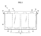
- FIG. 1 is a front view of a battery module 60 according to a first embodiment of the present invention.
- FIGS. 2A and 2B and FIGS. 3A and 3B are a front view, side view, top view, and bottom view, respectively, of a retention member 50 in a state that the retention member 50 retains laminate-sheathed cells 11 therein
- FIG. 4 is a front view of a printed-wiring board 51 constituting the retention member 50.
- FIG. 5 is a perspective view of an example of the laminate-sheathed cell 11
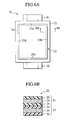
- FIG. 6A is a plan view of the laminate-sheathed cell 11
- FIG. 6B is a cross-sectional view taken along a line 6B-6B of FIG. 6A.
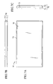
- FIG. 7A through FIG. 7C are a front view, a top view, and a side view, respectively, of a battery accommodation case 61 shown in FIG. 1.
- the battery module 60 includes: unit cells 11; the retention member 50 for retaining the unit cells 11 therein; and the battery accommodation case 61 for accommodating therein the retention member 50 for retaining the unit cells 11 therein.
- the retention member 50 is configured with the printed-wiring board 51 printed with voltage measurement wirings 52 for measuring voltages of the unit cells 11, respectively.
- the battery module further includes clipping members 53 detachably attached to the printed-wiring board 51, so as to electrically connect electrode terminals 41, 42 of the unit cells 11 to the voltage measurement wirings 52, respectively.
- Used as the unit cells 11 are laminate-sheathed cells each including an electric-power generating element encapsulated within a laminate film.
- the battery accommodation case 61 is simply called "case 61" hereinafter, when appropriate.
- the retention member 50 for retaining the laminate-sheathed cells 11 is configured with the printed-wiring board 51, in the battery module 60 of this embodiment. While the detailed explanation of the printed-wiring board 51 is omitted since the same belongs to a known technique, the printed-wiring board has a structure including wirings made of copper foils adhered onto obverse and reverse surfaces of an insulative board made of a non-electroconductive material such as bakelite or epoxy resin and having a thickness of several millimeters.
- the printed-wiring board 51 includes the insulative board, and is thus a relatively rigid plate material.
- the printed-wiring board 51 has retaining surfaces each having an elastic sheet 54 (corresponding to an elastic body) adhered thereto, and each elastic sheet 54 is electrically insulative and is compressed and elastically deformed by the associated laminate-sheathed cells 11 when the printed-wiring board 51 is accommodated within the battery accommodation case 61 (see a partially enlarged view in FIG. 2B).
- the printed-wiring board 51 retains a cell assembly 12 configured with a plurality of laminate-sheathed cells 11 electrically connected together.
- the plurality of laminate-sheathed cells 11 are retained on both obverse and reverse surfaces 51a and 51b of the printed-wiring board 51.
- the obverse surface 51a of the printed-wiring board 51 retains thereon four laminate-sheathed cells 11 aligned in a widthwise direction (right-and-left direction in FIG. 1)
- the reverse surface 51b of the printed-wiring board 51 also retains thereon four laminate-sheathed cells 11 aligned in the widthwise direction.
- totally eight laminate-sheathed cells 11 are connected together in series to constitute the cell assembly 12. In this way, it becomes possible to provide the battery module 60 capable of coping with a desired voltage, by connecting an appropriate number of laminate-sheathed cells 11 together in series.
- the laminate-sheathed cell 11 retained at the left end of the obverse surface 51a of the printed-wiring board 51 has its negative electrode terminal 42 placed in the associated recess 55 and connected to a positive electrode terminal 41 of the laminate-sheathed cell 11 retained at the left end of the reverse surface 51b.
- the laminate-sheathed cell 11 retained at the left end of the reverse surface 51b has its negative electrode terminal 42 placed at an upper portion of the reverse surface 51b and connected to a positive electrode terminal 41 of a rightward neighbored laminate-sheathed cell 11.
- the eight laminate-sheathed cells 11 are connected together in series. Further, the laminate-sheathed cell 11 at the left end of the obverse surface 51a has its positive electrode terminal 41 electrically connected with a positive terminal 63, while the laminate-sheathed cell 11 at the right end of the obverse surface 51a has its negative electrode terminal 42 electrically connected with a negative terminal 64.
- the printed-wiring board 51 is printed with a plurality (eight in the illustrated embodiment) of voltage measurement wirings 52 for measuring voltages of the plurality (eight in the illustrated embodiment) of laminate-sheathed cells 11, respectively (see FIG. 4).
- the plurality of voltage measurement wirings 52 are printed on the obverse and reverse surfaces 51a and 51b, respectively, since the plurality of laminate-sheathed cells 11 are retained on the obverse and reverse surfaces 51a and 51b of the printed-wiring board 51, respectively.
- eight voltage measurement wirings 52 (generic designation of 52a through 52h) are printed on the obverse surface 51a of the printed-wiring board 51, since four laminate-sheathed cells 11 are retained thereon.
- the reverse surface 51b is printed with eight voltage measurement wirings 52.
- measurement terminals 56 provided at one ends of the voltage measurement wirings 52e through 52h are arranged at inner edges 55a of the recesses 55, respectively, in this embodiment.
- measurement terminals 57 provided at one ends of the voltage measurement wirings 52a through 52d are arranged at an upper portion of the printed-wiring board 51 where the electrode terminals 41, 42 of the laminate-sheathed cells 11 are arranged.
- the electrode terminals 41, 42 of the retained laminate-sheathed cells 11 are overlapped with the measurement terminals 57, respectively.
- Electrode terminals 41, 42 of the laminate-sheathed cells 11 are electrically connected to the measurement terminals 57, respectively, by exemplarily soldering or ultrasonic welding these overlapped portions to each other.
- the other ends of the voltage measurement wirings 52 are connected to a terminal section 58 provided at a left end of the printed-wiring board 51.
- this terminal section 58 is detachably connected with a connector connected to an external controlling apparatus so that the external controlling apparatus is allowed to measure the voltages of the laminate-sheathed cells 11.
- the clipping members 53 are detachably attached to the recesses 55 of the printed-wiring board 51, respectively.
- Each clipping member 53 has right and left sides formed with grooves 53a to be fitted onto inner edges 55a of the associated recess 55, respectively.
- Each clipping member 53 is attached to the associated recess 55, by inserting the former into the latter while fitting the grooves 53a onto the inner edges 55a of the recess 55, respectively.
- electrode terminals 41, 42 of the associated obverse and reverse laminate-sheathed cells 11 are placed in each recess 55, and the associated clipping member 53 is formed with an accommodating space for accommodating therein the two electrode terminals 41, 42 positioned in the recess 55.
- each clipping member 53 is provided with an interior wiring 59 for electrically connecting: the two electrode terminals 41, 42 clipped in the clipping member; to the associated measurement terminal 56 arranged at the inner edge 55a of the associated recess 55.
- the interior wiring 59 is exemplarily configured with a thin metal plate attached to the inner surface which defines the accommodating space.
- Each clipping member 53 is to exhibit such an electrical connecting function, and another function to fixedly position the two electrode terminals 41, 42 in the recess 55, i.e., a positioning function for restricting the positions of the associated two laminate-sheathed cells 11 relative to the printed-wiring board 51. This enables to omit dedicated members and dedicated operations for duly positioning the laminate-sheathed cells 11.
- each clipping member 53 comprises an element having a spring nature capable of applying a clipping pressure to the electrode terminals 41, 42, thereby ensuring the connection therebetween. Meanwhile, it is also effective to provide a stopper such as a locking pawl for preventing the clipping member 53 from falling out of the recess 55.
- the printed-wiring board 51 retaining the plurality of laminate-sheathed cells 11 in the above manner is accommodated within the case 61.
- the case 61 includes upper and lower spaces filled with an insulative potting material such as a lower-temperature curing type of urethane-based potting material. Filling the potting material to thereby insulatingly encapsulate and fix the connecting circuit, restricts looseness of the laminate-sheathed cells 11, and prevents disconnection of the electrical connecting circuit adopting the bus-bars, for example.
- an insulative potting material such as a lower-temperature curing type of urethane-based potting material.
- each laminate-sheathed cell 11 includes: a pair of laminate films 21, 22 having flexibility; an electric-power generating element 31 encapsulated within the laminate films 21, 22 by heat-welding outer peripheries of the laminate films 21, 22 to each other; and positive and negative electrode terminals 41, 42 having one ends electrically connected to the electric-power generating element 31.
- the electrode terminals 41, 42 are connected to the opposite end surfaces of the electric-power generating element 31, respectively.
- the other ends of the electrode terminals 41, 42 are outwardly protruded from the outer peripheries of the laminate films 21, 22, respectively.
- the illustrated laminate-sheathed cell 11 is a lithium-ion secondary cell, for example, in which the stacked type of electric-power generating element 31 is provided by successively stacking a positive electrode plate, a negative electrode plate, and a separator, and is encapsulated within the laminate films 21, 22.
- the laminate-sheathed cell 11 including the stacked type of electric-power generating element 31 it is required to apply a pressure to grip the electric-power generating element 31 so as to keep the distance between the electrode plates constant to thereby maintain the cell performance.
- the printed-wiring board 51 in this embodiment has its retaining surfaces carrying elastic sheets 54 adhered thereto, and these elastic sheets 54 are to be compressed and elastically deformed by the laminate-sheathed cells 11 when the cells 11 are accommodated within the case 61 (see the partially enlarged view in FIG. 2B).
- Elastic deformation of the elastic sheets 54 allows the laminate-sheathed cells 11 to be accommodated within the case 61, in a state that the electric-power generating elements 31 are clamped between the case 61 and printed-wiring board 51.
- Usable as the elastic sheet 54 is an appropriate elastic material such as rubber or urethane.
- each of the laminate films 21, 22 is typically a composite sheet comprising two or more layers, and typically includes, from the inside to the outside, a sealing layer 24 to be heat-welded, a metal layer 25 such as an aluminum laminate film, and a resin layer 26 forming an outer sheath.
- the sealing layer 24 is formed of a heat-sealable resin.
- Applicable heat-sealable resin materials include those thermoplastic resin materials such as polypropylene (PP), polyethylene (PE) and the like.
- the laminate films 21, 22 have rectangular shapes, respectively, and are coated onto the associated electric-power generating element 31 in a manner to interpose it therebetween.
- the sealing layers 24 of the pair of laminate films 21, 22 are joined to each other by heat-welding, from the outer periphery of the associated electric-power generating element 31 to the outer ends of the laminate films.
- the aluminum plates constituting the electrode terminals 41, 42 are directly joined to the sealing layers 24, respectively, by heat-welding.
- the two sides 23a and 23c, through which the electrode terminals 41, 42 are protruded, respectively, are portions where small gaps are likely to be caused due to vibration transmitted via electrode terminals 41, 42. Therefore, the tear strengths at the sides 23a and 23c through which the electrode terminals 41, 42 are protruded, are generally increased as compared with tear strengths at the other two sides 23b and 23d.
- the tear strengths of the sides 23a and 23c are increased as compared with those of the sides 23b and 23d, by exemplarily applying surface treatment to the electrode terminals 41, 42, by adjusting the material of the sealing layers 24, or by changing the manner or conditions of heat-welding.
- the heat-welded outer periphery 23 is also called a "sealed portion 23".
- the predetermined pressure at which the heat-welded portion of the side 23b or side 23d is torn can be appropriately set by exemplarily varying the width of the sealed portion 23 or the heat-welding conditions, and the predetermined pressure may be about 1 kgf/cm 2 , for example.
- the case 61 includes: a casing 70 exhibiting a substantially flat shape so as to accommodate the laminate-sheathed cells 11 therein, in a hermetically sealed state; and a tearing valve (not shown) for releasing a gas generated from the laminate-sheathed cell 11 and spread within the casing 70 upon abnormality, toward the exterior, when the gas pressure has reached the predetermined pressure.
- the casing 70 includes first and second casing halves 71 and 72 to be abutted onto each other to thereby define a cell accommodating space within the casing 70.
- the first and second casing halves 71 and 72 have flat rectangular shapes (see FIG. 7A), respectively, and have arcuately rounded upper end portions and lower end portions (see FIG. 7C), respectively.
- the dimensions of the casing 70 may be appropriately selected.
- the casing 70 in the illustrated embodiment has such dimensions to accommodate therein the printed-wiring board 51 which retains totally eight laminate-sheathed cells 11 comprising four and four laminate-sheathed cells 11 aligned in the widthwise direction on the obverse and reverse surfaces 51a and 51b of the printed-wiring board 51, respectively.
- first and second casing halves 71 and 72 are made of metal material such as aluminum or stainless steel from a standpoint of cooling performance and strength.
- the first and second casing halves 71 and 72 are fastened to each other by fastening screws (not shown) such that the cell accommodating space is brought into a hermetically sealed state and is sealed from moisture. It is possible to enhance the water-tightness at the abutted surfaces of the first and second casing halves 71 and 72, by exemplarily coating a sealing material thereon, or by interposing a sealing member like a packing therebetween.
- a circular through-hole 73 defined between the abutted side surfaces of the first and second casing halves 71 and 72, is a circular through-hole 73 in which the positive terminal 63 and negative terminal 64 of the cell assembly 12 are arranged (see FIG. 1).
- the casing 70 is provided with one or more tearing valves. It is possible to employ an appropriate constitution for the tearing valve, and the tearing valve exemplarily includes: a gas releasing hole opened at the casing 70; and a sealing plate for sealing the gas releasing hole and for opening the gas releasing hole when the internal pressure of the casing 70 has reached a predetermined pressure.
- the sealing plate is formed of an appropriate material such as a sealing material, metal material or resin material, and is mounted by a joiner such as adhesive or heat sealing in a manner to seal the gas releasing hole.
- the predetermined pressure at which the tearing valve is operated, can be appropriately set by exemplarily changing the material, the wall thickness of the sealing plate, the kind of adhesive to be used, and/or the heat-welding conditions, and the predetermined pressure is set to be the same as the pressure, at which the sealed portion 23 of the laminate-sheathed cell 11 is torn, i.e., about 1 kgf/cm 2 , for example.
- the elastic sheets 54 are firstly adhered onto the retaining surfaces of the obverse and reverse surfaces 51a and 51b of the printed-wiring board 51 printed with the voltage measurement wirings 52, respectively.
- the printed-wiring board 51 is then oriented horizontally, and four laminate-sheathed cells 11 are arranged thereon while placing the applicable electrode terminals 41, 42 into the associated recesses 55, respectively.
- the sides 23b and 23d of the two laminate-sheathed cells 11 at the left side are overlapped with each other, and the sides 23b and 23d of the other two laminate-sheathed cells 11 at the right side are overlapped with each other (see FIG. 2).
- the applicable electrode terminals 41, 42 are overlapped with the associated measurement terminals 57, respectively.
- the four laminate-sheathed cells 11 are temporarily fixed, and the overlapped portions in this state are soldered or ultrasonic welded to each other, to thereby electrically connect the electrode terminals 41, 42 of the laminate-sheathed cells 11 to the measurement terminals 57, respectively.
- the positive electrode terminal 41 of the leftmost laminate-sheathed cell 11 on the obverse surface 51a is electrically connected with the positive terminal 63
- the negative electrode terminal 42 of the rightmost laminate-sheathed cell 11 on the obverse surface 51a is electrically connected with the negative terminal 64.
- the printed-wiring board 51 in the state where the four laminate-sheathed cells 11 are temporarily fixed thereon, is turned over back to front, and then the remaining four laminate-sheathed cells 11 are arranged and the electrode terminals 41, 42 thereof are connected to the associated measurement terminals 57, respectively, in the same manner as the above. This results in a state that the electrode terminals 41, 42 of the paired two laminate-sheathed cells 11 on the obverse and reverse sides, respectively, are positioned in the associated recess 55 of the printed-wiring board 51.
- each clipping member 53 is fitted into the associated recess 55, while inserting the associated electrode terminals 41, 42 into the accommodating space for the clipping member 53. This simultaneously completes both the electrical connection between the two electrode terminals 41, 42 positioned within the associated recess 55, and the electrical connection between the electrode terminals 41, 42 and the associated voltage measurement wiring 52.
- the temporary fixation of the laminate-sheathed cells 11 is quitted, and the printed-wiring board 51 retaining thereon the plurality of laminate-sheathed cells 11 is accommodated into the case 61 and the potting material is filled thereinto, for example, thereby completing the assembling of the battery module 60.
- the retention member 50 for retaining the laminate-sheathed cells 11 is configured with the printed-wiring board 51 printed with the voltage measurement wirings 52 for measuring the voltages of the laminate-sheathed cells 11, respectively, so that the laminate-sheathed cells 11 are retained by the relatively rigid printed-wiring board 51, thereby facilitating the handling of the laminate-sheathed cells 11 and increasing the production efficiency. Further, the voltage measuring operation such as the cable drawing-around operation in the conventional can be drastically reduced.
- the battery module further includes the clipping members 53 detachably attached to the printed-wiring board 51 to thereby electrically connect the electrode terminals 41, 42 of the laminate-sheathed cells 11 to the voltage measurement wirings 52, respectively, thereby allowing to simultaneously complete both the electrical connection between the paired two electrode terminals 41, 42 positioned within the associated recess 55, and the electrical connection between the electrode terminals 41, 42 and the associated voltage measurement wiring 52, so that the production efficiency can be further increased.
- Each clipping member 53 further has a positioning function for restricting the positions of the associated laminate-sheathed cells 11 relative to the printed-wiring board 51, thereby enabling to omit dedicated members and dedicated operations for duly positioning the laminate-sheathed cells 11, so that the production efficiency can be further increased.
- the battery module further includes the elastic sheets 54 which are provided on the retaining surfaces of the printed-wiring board 51 and which are compressed and elastically deformed by the laminate-sheathed cells 11 when the printed-wiring board is accommodated into the battery accommodation case.
- the electric-power generating elements 31 can be pressurized and gripped, thereby allowing to keep distances between electrode plates constant, to thereby maintain the cell performance and prolong the service life.
- the printed-wiring board 51 retains the cell assembly 12 configured with the plurality of laminate-sheathed cells 11 electrically connected together and the printed-wiring board 51 is printed with the plurality of voltage measurement wirings 52 for measuring the voltages of the plurality of laminate-sheathed cells 11, respectively, so that many laminate-sheathed cells 11 can be easily handled and the production efficiency can be further increased. Moreover, the voltage measuring operation such as the cable drawing-around operation can be drastically reduced, thereby also enabling to downsize the power source.
- the plurality of laminate-sheathed cells 11 are retained by the obverse and reverse surfaces 51a and 51b of the printed-wiring board 51 and the plurality of voltage measurement wirings 52 are printed on the obverse and reverse surfaces 51a and 51b of the printed-wiring board 51, so that the battery module can be downsized by effectively utilizing the widthwise direction of the printed-wiring board 51 to the utmost, and so that the laminate-sheathed cells 11 provided on the obverse and reverse surfaces are allowed to independently conduct heat dissipation to thereby restrict degradation of the cell performance.
- Each unit cell 11 is the laminate-sheathed cell 11 comprising the electric-power generating element encapsulated within the laminate film, thereby allowing to provide the light-weighted battery module 60.
- the battery module 60 is not limited to the details described with respect to the above embodiment, and the conventionally known measures may be appropriately adopted.
- the electrode terminals 41, 42 of the paired two laminate-sheathed cells 11 may be coupled to each other, by heat-welding, laser welding, electron-beam welding, by a rivet, or by a caulking technique.
- the illustrated laminate-sheathed cell 11 is provided in the configuration that the positive and negative electrode terminals 41, 42 for the associated electric-power generating element 31 are connected to the opposite end surfaces of the electric-power generating element 31, respectively.
- the present invention is also applicable to a situation for accommodating a laminate-sheathed cell provided in a configuration where both positive and negative electrode terminals 41, 42 are connected to one end surface of the associated electric-power generating element 31.
- FIG. 8 is a perspective view of a combination battery 90 according to a second embodiment of the present invention
- FIG. 9 is a schematic view of a vehicle 100 comprising the combination battery 90 mounted thereon.
- the combination battery 90 of the second embodiment is configured by stacking a plurality of battery modules 60 according to the first embodiment, via clearances 97 for flowing cooling air C therethrough. While the dimension of each clearance 97 may be appropriately set, there can be exemplarily adopted a dimension within a range of 2mm to 4mm from a standpoint for stacking the battery modules in as many stages as possible within a limited space and for realizing a preferable flow of cooling air C.
- the illustrated embodiment includes the combination battery 90 configured by electrically connecting the plurality of battery modules in parallel. Preparing the plurality of battery modules into the combination battery 90 enables to deal with the demand for a battery capacity or output for each purpose of use, in a relatively inexpensive manner without fabricating a newly dedicated type of battery module 60.
- the positive terminals 63 and negative terminals 64 of the battery modules 60 are electrically connected to each other, by a positive-terminal coupling plate 91 having an outer positive-terminal portion 91a and a negative-terminal coupling plate 92 having an outer negative-terminal portion 92a, respectively.
- each case 61 is provided with screw-hole portions (not shown) at both sides, and the battery modules 60 are coupled to one another by fixing, joint plates 93 having opening portions corresponding to the screw-hole portions, to the screw-hole portions by setscrews 94, respectively.
- the positive terminals 63 and negative terminals 64 of the battery modules 60 are protected by a positive-electrode insulating cover 95 and a negative-electrode insulating cover 96, respectively, and distinguished from each other by appropriate coloring such as red and blue.
- a positive-electrode insulating cover 95 and a negative-electrode insulating cover 96 are protected by a positive-electrode insulating cover 95 and a negative-electrode insulating cover 96, respectively, and distinguished from each other by appropriate coloring such as red and blue.
- the clearances 97 for passing therethrough the cooling air C, respectively.
- the combination battery 90 can be repaired by simply replacing the troubled element(s).
- the combination battery 90 When the combination battery 90 is to be installed in an electric vehicle (EV) 100 as shown in FIG. 9, it is installed under a seat at the central portion of the vehicular body. This is because, the installment under the seat enables to reserve a wider in-vehicle space and a wider trunk room. Note that the combination battery installment position is not limited to that under the seat, and may be under a rear trunk room. In case of an EV or FCV (fuel-cell vehicle) without engines, the combination battery may be installed at a front part of the vehicle where an engine was typically installed.
- EV electric vehicle
- FCV fuel-cell vehicle
- each laminate-sheathed cell 11 is relatively light-weighted as compared with a cell using a metallic outer canister, thereby contributing to lightening the combination battery 90, thus the whole of the vehicle 100, and therefore contributing to improving the mileage of an EV vehicle, for example.
- the combination battery 90 according to the second embodiment is configured by stacking the plurality of battery modules 60, the combination battery 90 can be obtained in various capacities and/or voltages by simply changing the number of fundamental or elemental battery modules 60 or by changing the connecting manner thereof.
- installment of the battery module 60 or combination battery 90 prevents an excessively increased weight of the vehicle 100 and prevents an excessively narrowed effective space, thereby enabling to provide the vehicle 100 superior in the mileage and running performance.
- the combination battery 90 provided by vertically stacking the plurality of battery modules 60 has been illustrated, the assembling direction is not limited to the vertical.
- the combination battery may be established such that a plurality of vertically upstanding battery modules 60 are juxtaposed with each other in a lateral direction.
- the installing manner is not limited to the combination battery 90 in the EV, for example, and it is possible to install a battery module(s) 60 only, or a combination of combination battery 90 and battery module(s) 60, depending on the usage in a suitable vehicle.
- the vehicle 100, in which the battery module 60 or combination battery 90 of the present invention can be installed preferably includes an EV, FCV or hybrid electric vehicle (HEV), without limited thereto.
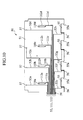
- FIG. 10 is a front view of a printed-wiring board constituting a retention member according to a third embodiment of the present invention.
- the third embodiment is provided by adding temperature detectors 110 (generic term for 110a through 110d), and temperature measurement wirings 111 (generic term for 111a through 111d) and 112 (generic term for 112a through 112d) to the printed-wiring board of the first embodiment, and constituent elements identical with those of the first embodiment are denoted by the same reference numerals and the explanation thereof shall be omitted.
- Each temperature detector 110 comprises a wiring such as a K type of thermocouple or a thermistor, which preferably has a measuring range of about -50°C to +100°C.
- the temperature detector is configured with a printed wiring to thereby exclude any irregularity at the arrangement surface for the associated laminate-sheathed cell 11, it is also possible to exemplarily attach such a small-sized chip as the temperature detector to the board, which chip never obstructs the arrangement of the laminate-sheathed cell 11.
- the above temperature detector 110 are arranged at the arranging positions of the plurality of laminate-sheathed cells 11 on the printed-wiring board 51, respectively, and are connected to the terminal section 58 via temperature measurement wirings 111, 112, respectively. Also, the temperature detector 110 and temperature measurement wirings 111, 112 are arranged on the opposite surface of the printed-wiring board 51.
- the terminal section 58 is connected to a power-source controlling part (not shown), thereby allowing to detect the temperatures of the laminate-sheathed cells, respectively.
- the third embodiment it becomes possible to omit separate provision of the temperature detector themselves as well as separate wirings for the temperature detector, in addition to the effects provided by the first embodiment.
- the temperature detector 110 have been arranged for the individual laminate-sheathed cells 11 in this embodiment, respectively, it is also possible to decrease the number of temperature detector depending on the requirement of temperature management. In that case, it is possible to detect the temperature of a specific laminate-sheathed cell(s) 11 only, or to detect the temperature of the whole assembly of the laminate-sheathed cells 11 at a position offset from the arranging positions of the laminate-sheathed cells 11.
- FIG. 11 through FIG. 14 relate to an improvement of the bus-bars 80 for mutually connecting the upper electrode terminals 41, 42 (right and left terminals) of the neighboring laminate-sheathed cells 11 on the printed-wiring board of the first embodiment, respectively.
- the bus-bars in the first embodiment have been connected to the electrode terminals 41, 42 by soldering or ultrasonic welding, and these electrode terminals have been soldered or ultrasonic welded to the measurement terminals 57, respectively, so as to ensure the connection therewith.
- the bus-bars are fixed to the board by fastener such as bolt or rivet.
- the electrode terminals 41, 42 are clamped between the bus-bars and the board, respectively, thereby ensuring electrical connections between the bus-bars and electrode terminals by crimping, respectively.
- measurement terminals 57 are arranged at the fastening locations, the connection between the electrode terminals and the measurement terminals 57 can also be ensured.
- the fastening positions are arranged at locations other than the electrode terminals, as shown in FIG. 11A. Such an arrangement enables to simultaneously obtain the electrical connection between the electrode terminals and bus-bars and the electrical connection between the electrode terminals and measurement terminals 57, respectively.
- FIG. 12A is a see-through rear view of the battery module, and the electrode terminals 41, 42 are clamped between the bus-bars and the board similarly to the obverse surface of the board, thereby ensuring the electrical connection between the electrode terminals and the bus-bars by crimping. Further, the measurement terminals 57 are arranged at the fastening locations, respectively, thereby allowing to ensure the electrical connections between the electrode terminals and the measurement terminals 57, respectively.
- FIG. 13 and FIG. 14 show another version of the fourth embodiment which is characterized in that the measurement terminals 57 are arranged on only one side of the board. Namely, electroconductive materials are used as the fastener, for electrical connection from the bus-bars or electrode terminals at the reverse surface side to the measurement terminals at the obverse surface side of the board. This allows to limit the printed surface of the printed-wiring board to only one side thereof, thereby achieving an advantageous cost performance.
- the cell voltage can be monitored without welding. Further, the bus-bars can be fixed to the printed-wiring board 51, thereby improving the vibration resistance.
- the present invention is not limited thereto and can be applied to a battery module including a plurality of unit cells connected in parallel by utilizing such a feature of a printed-wiring board that the freedom degree of wiring pattern is high. It is also possible to form: a wiring pattern having the function of the bus-bars 80 for connecting the electrode terminals 41, 42 to each other; on the printed-wiring board.
- the present invention can be used in an application for facilitating the handling of unit cells and for enhancing the production efficiency.
Landscapes
- Chemical & Material Sciences (AREA)
- Chemical Kinetics & Catalysis (AREA)
- Electrochemistry (AREA)
- General Chemical & Material Sciences (AREA)
- Engineering & Computer Science (AREA)
- Manufacturing & Machinery (AREA)
- Battery Mounting, Suspending (AREA)
- Connection Of Batteries Or Terminals (AREA)
Applications Claiming Priority (4)
| Application Number | Priority Date | Filing Date | Title |
|---|---|---|---|
| JP2003353528 | 2003-10-14 | ||
| JP2003353528 | 2003-10-14 | ||
| JP2004243810A JP4701658B2 (ja) | 2003-10-14 | 2004-08-24 | 電池モジュール、および、組電池 |
| JP2004243810 | 2004-08-24 |
Publications (3)
| Publication Number | Publication Date |
|---|---|
| EP1524717A2 true EP1524717A2 (de) | 2005-04-20 |
| EP1524717A3 EP1524717A3 (de) | 2007-08-29 |
| EP1524717B1 EP1524717B1 (de) | 2010-07-07 |
Family
ID=34380415
Family Applications (1)
| Application Number | Title | Priority Date | Filing Date |
|---|---|---|---|
| EP04024222A Expired - Lifetime EP1524717B1 (de) | 2003-10-14 | 2004-10-11 | Batteriemodul und Kombinationsbatterie |
Country Status (5)
| Country | Link |
|---|---|
| US (1) | US7504178B2 (de) |
| EP (1) | EP1524717B1 (de) |
| JP (1) | JP4701658B2 (de) |
| CN (1) | CN100337343C (de) |
| DE (1) | DE602004027981D1 (de) |
Cited By (4)
| Publication number | Priority date | Publication date | Assignee | Title |
|---|---|---|---|---|
| WO2007112116A3 (en) * | 2006-03-27 | 2008-01-31 | Alcoa Inc | Integrated module connection for hev battery |
| EP1519430A3 (de) * | 2003-09-29 | 2008-11-19 | Nissan Motor Co., Ltd. | Batteriegehäuse, Batteriemodul und zusammengesetze Batterie |
| EP3591732A4 (de) * | 2017-02-28 | 2020-03-11 | Yura Corporation Co., Ltd. | Rahmenanordnung und verfahren zur herstellung davon |
| CN115395180A (zh) * | 2021-05-24 | 2022-11-25 | 三星Sdi株式会社 | 电池组 |
Families Citing this family (44)
| Publication number | Priority date | Publication date | Assignee | Title |
|---|---|---|---|---|
| JP4977356B2 (ja) * | 2005-10-26 | 2012-07-18 | 日本電気株式会社 | 電気デバイス集合体 |
| EP2919295B1 (de) * | 2005-10-31 | 2018-08-29 | Black & Decker, Inc. | Verfahren zum anordnen die komponenten eines batteriepacks |
| WO2007102672A1 (en) * | 2006-03-06 | 2007-09-13 | Lg Chem, Ltd. | Battery module |
| US9484591B2 (en) * | 2006-03-06 | 2016-11-01 | Lg Chem, Ltd. | Voltage sensing member and battery module employed with the same |
| JP5344932B2 (ja) | 2006-03-06 | 2013-11-20 | エルジー・ケム・リミテッド | 中型または大型電池モジュール |
| KR100948002B1 (ko) * | 2006-03-06 | 2010-03-18 | 주식회사 엘지화학 | 중대형 전지모듈 |
| JP2008010501A (ja) * | 2006-06-27 | 2008-01-17 | Mitsumi Electric Co Ltd | 回路基板装置 |
| US8568915B2 (en) * | 2006-08-11 | 2013-10-29 | Johnson Controls—SAFT Power Solutions LLC | Battery with integrally formed terminal |
| KR100863729B1 (ko) * | 2006-09-18 | 2008-10-16 | 주식회사 엘지화학 | 전지모듈 인터페이스 |
| US11660971B2 (en) | 2006-11-07 | 2023-05-30 | Clarios Advanced Solutions Llc | System for arranging and coupling battery cells in a battery module |
| CN101627490B (zh) * | 2006-12-14 | 2012-10-03 | 江森自控帅福得先进能源动力系统有限责任公司 | 电池模块 |
| US9196922B2 (en) | 2007-02-08 | 2015-11-24 | Lg Chem, Ltd. | Lithium secondary battery of improved high-temperature cycle life characteristics |
| WO2008096961A1 (en) * | 2007-02-08 | 2008-08-14 | Lg Chem, Ltd. | Lithium secondary battery of improved high-temperature cycle life characteristics |
| WO2009016476A2 (en) * | 2007-07-30 | 2009-02-05 | Johnson Controls - Saft Advanced Power Solutions Llc | Storage battery arrangement |
| EP2191524B1 (de) | 2007-08-14 | 2018-10-10 | Cobasys, LLC | Batteriemodul |
| JP4780079B2 (ja) * | 2007-10-15 | 2011-09-28 | ソニー株式会社 | 電池パック及びその製造方法 |
| JP4386131B2 (ja) * | 2007-12-05 | 2009-12-16 | 三菱自動車工業株式会社 | 電気自動車 |
| DE102008013188A1 (de) * | 2008-03-07 | 2009-09-17 | Johnson Controls Hybrid And Recycling Gmbh | Elektrochemischer Akkumulator und Fahrzeug mit einem elektrochemischen Akkumulator |
| US7891495B2 (en) * | 2008-05-06 | 2011-02-22 | Harris Corporation | Battery bag |
| PE20110470A1 (es) | 2008-06-27 | 2011-07-15 | Proterra Inc | Sistemas y metodos de baterias para vehiculos |
| US8999538B2 (en) * | 2008-08-14 | 2015-04-07 | Johnson Controls—SAFT Advanced Power Solutions LLC | Battery module with sealed vent chamber |
| JP5285997B2 (ja) * | 2008-08-27 | 2013-09-11 | 矢崎総業株式会社 | 電源装置 |
| WO2010056750A2 (en) | 2008-11-12 | 2010-05-20 | Johnson Controls - Saft Advanced Power Solutions Llc | Battery system with heat exchanger |
| JP5472570B2 (ja) * | 2009-01-07 | 2014-04-16 | 三菱自動車工業株式会社 | 二次電池の電圧検出装置 |
| WO2010138209A1 (en) * | 2009-05-28 | 2010-12-02 | Phoenix Motorcars, Inc. | Battery module with related devices and methods |
| JP5509684B2 (ja) * | 2009-06-03 | 2014-06-04 | ソニー株式会社 | 電池パック |
| KR101146616B1 (ko) * | 2009-06-30 | 2012-05-14 | 지에스나노텍 주식회사 | 박막 전지 및 박막 전지의 전극 단자를 접합하는 방법 |
| DE102010007633A1 (de) * | 2010-02-05 | 2011-08-11 | Dr. Ing. h.c. F. Porsche Aktiengesellschaft, 70435 | Fahrzeug mit elektrischer Antriebsvorrichtung |
| JP5445360B2 (ja) * | 2010-07-05 | 2014-03-19 | 株式会社デンソー | 組電池 |
| US8617730B2 (en) * | 2010-09-30 | 2013-12-31 | Honda Motor Co., Ltd. | Battery for electric vehicle |
| US9005794B2 (en) | 2011-10-21 | 2015-04-14 | Tyco Electronics Corporation | Battery connector system |
| US8883332B2 (en) * | 2011-12-09 | 2014-11-11 | Samsung Sdi Co., Ltd. | Rechargeable secondary battery |
| DE102012221751A1 (de) * | 2012-11-28 | 2014-05-28 | Robert Bosch Gmbh | Batteriemodul mit Batteriemodulabdeckung sowie ein Verfahren zur Herstellung einer Batteriemodulabdeckung eines Batteriemoduls |
| DE102013202367B4 (de) * | 2013-02-14 | 2024-04-04 | Robert Bosch Gmbh | Energiespeichermodul mit einem durch eine Folie gebildeten Modulgehäuse und mehreren jeweils in einer Aufnahmetasche des Modulgehäuses angeordneten Speicherzellen, sowie Energiespeicher und Kraftfahrzeug |
| US9831482B2 (en) | 2013-09-06 | 2017-11-28 | Johnson Controls Technology Company | Battery module lid system and method |
| US9972869B2 (en) * | 2014-01-31 | 2018-05-15 | Lg Chem, Ltd. | Battery cell assembly having improved thermal sensing capability |
| JP6363529B2 (ja) * | 2015-02-13 | 2018-07-25 | 株式会社Soken | 電池制御装置 |
| KR102115482B1 (ko) * | 2016-09-29 | 2020-05-26 | 주식회사 엘지화학 | 배터리 팩 |
| CN106585353A (zh) * | 2016-12-09 | 2017-04-26 | 李伟 | 低耗能汽车 |
| US20190305265A1 (en) * | 2018-03-27 | 2019-10-03 | Rivian Ip Holdings, Llc | Shear wall with integrated conductors |
| US11228070B2 (en) * | 2019-11-11 | 2022-01-18 | Ford Global Technologies, Llc | Efficient electric architectural layouts for electrified vehicles |
| US12046775B2 (en) * | 2021-06-24 | 2024-07-23 | Rivian Ip Holdings, Llc | Battery module flex circuit |
| EP4399763A4 (de) | 2021-09-10 | 2025-07-09 | Milwaukee Electric Tool Corp | Batteriepack |
| CN115528391B (zh) * | 2022-09-23 | 2024-06-04 | 欣旺达惠州动力新能源有限公司 | 电芯组与电压采集方法 |
Family Cites Families (13)
| Publication number | Priority date | Publication date | Assignee | Title |
|---|---|---|---|---|
| JPH08203483A (ja) * | 1995-01-26 | 1996-08-09 | Matsushita Electric Ind Co Ltd | 電池電源装置 |
| US6141223A (en) * | 1998-05-08 | 2000-10-31 | Smk Manufacturing, Inc. | Battery assembly for supplying power to an integrated circuit |
| GB9900396D0 (en) * | 1999-01-08 | 1999-02-24 | Danionics As | Arrangements of electrochemical cells |
| US6399238B1 (en) * | 1999-12-13 | 2002-06-04 | Alcatel | Module configuration |
| US6423441B1 (en) * | 2000-01-12 | 2002-07-23 | Delphi Technologies, Inc. | Battery pack signal routing system |
| JP2001256937A (ja) * | 2000-03-14 | 2001-09-21 | Matsushita Electric Ind Co Ltd | 組電池及び電池パック |
| JP2001345081A (ja) * | 2000-05-31 | 2001-12-14 | Japan Storage Battery Co Ltd | 非水電解質二次電池 |
| JP2002216722A (ja) * | 2001-01-17 | 2002-08-02 | Gs-Melcotec Co Ltd | 組電池及び組電池の製造方法 |
| US6729908B2 (en) * | 2001-07-31 | 2004-05-04 | Delphi Technologies, Inc. | Battery pack having perforated terminal arrangement |
| JP4292451B2 (ja) * | 2001-12-26 | 2009-07-08 | ソニー株式会社 | バッテリパック |
| US7198866B2 (en) * | 2002-07-09 | 2007-04-03 | Nissan Motor Co., Ltd. | Cell assembly |
| JP3767526B2 (ja) * | 2002-07-09 | 2006-04-19 | 日産自動車株式会社 | 電池集合体 |
| JP3832397B2 (ja) * | 2002-07-24 | 2006-10-11 | 日産自動車株式会社 | 薄型電池モジュール |
-
2004
- 2004-08-24 JP JP2004243810A patent/JP4701658B2/ja not_active Expired - Fee Related
- 2004-10-11 EP EP04024222A patent/EP1524717B1/de not_active Expired - Lifetime
- 2004-10-11 DE DE602004027981T patent/DE602004027981D1/de not_active Expired - Lifetime
- 2004-10-12 US US10/961,232 patent/US7504178B2/en not_active Expired - Fee Related
- 2004-10-14 CN CNB2004100881937A patent/CN100337343C/zh not_active Expired - Fee Related
Cited By (6)
| Publication number | Priority date | Publication date | Assignee | Title |
|---|---|---|---|---|
| EP1519430A3 (de) * | 2003-09-29 | 2008-11-19 | Nissan Motor Co., Ltd. | Batteriegehäuse, Batteriemodul und zusammengesetze Batterie |
| WO2007112116A3 (en) * | 2006-03-27 | 2008-01-31 | Alcoa Inc | Integrated module connection for hev battery |
| EP3591732A4 (de) * | 2017-02-28 | 2020-03-11 | Yura Corporation Co., Ltd. | Rahmenanordnung und verfahren zur herstellung davon |
| US11217850B2 (en) | 2017-02-28 | 2022-01-04 | Yura Corporation Co., Ltd. | Frame assembly and method for manufacturing same |
| CN115395180A (zh) * | 2021-05-24 | 2022-11-25 | 三星Sdi株式会社 | 电池组 |
| EP4102631A3 (de) * | 2021-05-24 | 2023-03-15 | Samsung SDI Co., Ltd. | Batteriepack |
Also Published As
| Publication number | Publication date |
|---|---|
| EP1524717B1 (de) | 2010-07-07 |
| DE602004027981D1 (de) | 2010-08-19 |
| US20060040173A1 (en) | 2006-02-23 |
| CN1641904A (zh) | 2005-07-20 |
| JP2005142148A (ja) | 2005-06-02 |
| EP1524717A3 (de) | 2007-08-29 |
| US7504178B2 (en) | 2009-03-17 |
| JP4701658B2 (ja) | 2011-06-15 |
| CN100337343C (zh) | 2007-09-12 |
Similar Documents
| Publication | Publication Date | Title |
|---|---|---|
| US7504178B2 (en) | Battery module and combination battery | |
| US9269934B2 (en) | Battery module | |
| KR100900854B1 (ko) | 전지 모듈 | |
| JP5154451B2 (ja) | バッテリーモジュール | |
| KR101161135B1 (ko) | 중대형 전지모듈 | |
| EP1519430A2 (de) | Batteriegehäuse, Batteriemodul und zusammengesetze Batterie | |
| JP2013533579A (ja) | 新規構造を有するバッテリーモジュール | |
| CN101395739A (zh) | 蓄电池模块 | |
| KR20070112489A (ko) | 중대형 전지모듈 | |
| JP5240963B2 (ja) | 組電池 | |
| KR20070112490A (ko) | 전지모듈 | |
| CN111971814A (zh) | 电池组和电池模块 | |
| JP7596525B2 (ja) | 電池モジュールおよびその製造方法 | |
| JP2023541159A (ja) | 電池モジュールおよびこれを含む電池パック | |
| JP7434572B2 (ja) | 電池モジュール、それを含む電池パックおよびその製造方法 | |
| JP2022501770A (ja) | 電池パックおよびこれを含むデバイス | |
| KR20130022503A (ko) | 이차전지 | |
| CN116783761A (zh) | 电池模块及包括该电池模块的电池组 | |
| US20230040116A1 (en) | Energy storage apparatus | |
| US12424691B2 (en) | Energy storage apparatus | |
| CN115136382A (zh) | 电池模块、包括该电池模块的电池组及该电池模块的制造方法 | |
| JP2019186043A (ja) | 端子部品 | |
| KR20120074426A (ko) | 신규한 구조의 단위모듈 및 이를 포함하는 전지모듈 | |
| CN115702357A (zh) | 电池模块感测单元及其制造方法 | |
| KR102807202B1 (ko) | 전지 |
Legal Events
| Date | Code | Title | Description |
|---|---|---|---|
| PUAI | Public reference made under article 153(3) epc to a published international application that has entered the european phase |
Free format text: ORIGINAL CODE: 0009012 |
|
| 17P | Request for examination filed |
Effective date: 20041011 |
|
| AK | Designated contracting states |
Kind code of ref document: A2 Designated state(s): AT BE BG CH CY CZ DE DK EE ES FI FR GB GR HU IE IT LI LU MC NL PL PT RO SE SI SK TR |
|
| AX | Request for extension of the european patent |
Extension state: AL HR LT LV MK |
|
| PUAL | Search report despatched |
Free format text: ORIGINAL CODE: 0009013 |
|
| AK | Designated contracting states |
Kind code of ref document: A3 Designated state(s): AT BE BG CH CY CZ DE DK EE ES FI FR GB GR HU IE IT LI LU MC NL PL PT RO SE SI SK TR |
|
| AX | Request for extension of the european patent |
Extension state: AL HR LT LV MK |
|
| 17Q | First examination report despatched |
Effective date: 20080102 |
|
| AKX | Designation fees paid |
Designated state(s): DE FR GB |
|
| GRAP | Despatch of communication of intention to grant a patent |
Free format text: ORIGINAL CODE: EPIDOSNIGR1 |
|
| RIC1 | Information provided on ipc code assigned before grant |
Ipc: H01M 10/48 20060101ALI20100208BHEP Ipc: H01M 10/05 20100101AFI20100208BHEP |
|
| GRAS | Grant fee paid |
Free format text: ORIGINAL CODE: EPIDOSNIGR3 |
|
| GRAA | (expected) grant |
Free format text: ORIGINAL CODE: 0009210 |
|
| AK | Designated contracting states |
Kind code of ref document: B1 Designated state(s): DE FR GB |
|
| REG | Reference to a national code |
Ref country code: GB Ref legal event code: FG4D |
|
| REF | Corresponds to: |
Ref document number: 602004027981 Country of ref document: DE Date of ref document: 20100819 Kind code of ref document: P |
|
| PLBE | No opposition filed within time limit |
Free format text: ORIGINAL CODE: 0009261 |
|
| STAA | Information on the status of an ep patent application or granted ep patent |
Free format text: STATUS: NO OPPOSITION FILED WITHIN TIME LIMIT |
|
| 26N | No opposition filed |
Effective date: 20110408 |
|
| REG | Reference to a national code |
Ref country code: DE Ref legal event code: R097 Ref document number: 602004027981 Country of ref document: DE Effective date: 20110408 |
|
| PGFP | Annual fee paid to national office [announced via postgrant information from national office to epo] |
Ref country code: FR Payment date: 20141008 Year of fee payment: 11 Ref country code: DE Payment date: 20141007 Year of fee payment: 11 Ref country code: GB Payment date: 20141008 Year of fee payment: 11 |
|
| REG | Reference to a national code |
Ref country code: DE Ref legal event code: R119 Ref document number: 602004027981 Country of ref document: DE |
|
| GBPC | Gb: european patent ceased through non-payment of renewal fee |
Effective date: 20151011 |
|
| PG25 | Lapsed in a contracting state [announced via postgrant information from national office to epo] |
Ref country code: GB Free format text: LAPSE BECAUSE OF NON-PAYMENT OF DUE FEES Effective date: 20151011 Ref country code: DE Free format text: LAPSE BECAUSE OF NON-PAYMENT OF DUE FEES Effective date: 20160503 |
|
| REG | Reference to a national code |
Ref country code: FR Ref legal event code: ST Effective date: 20160630 |
|
| PG25 | Lapsed in a contracting state [announced via postgrant information from national office to epo] |
Ref country code: FR Free format text: LAPSE BECAUSE OF NON-PAYMENT OF DUE FEES Effective date: 20151102 |