EP1524547B1 - Federscharnier insbesondere für einstückige Bügel - Google Patents
Federscharnier insbesondere für einstückige Bügel Download PDFInfo
- Publication number
- EP1524547B1 EP1524547B1 EP04020767A EP04020767A EP1524547B1 EP 1524547 B1 EP1524547 B1 EP 1524547B1 EP 04020767 A EP04020767 A EP 04020767A EP 04020767 A EP04020767 A EP 04020767A EP 1524547 B1 EP1524547 B1 EP 1524547B1
- Authority
- EP
- European Patent Office
- Prior art keywords
- seat
- lug
- elastic
- temple
- elastic hinge
- Prior art date
- Legal status (The legal status is an assumption and is not a legal conclusion. Google has not performed a legal analysis and makes no representation as to the accuracy of the status listed.)
- Expired - Lifetime
Links
- 239000000463 material Substances 0.000 claims description 5
- 238000000034 method Methods 0.000 claims description 5
- 229920003023 plastic Polymers 0.000 claims description 4
- 239000004033 plastic Substances 0.000 claims description 4
- 230000008878 coupling Effects 0.000 description 5
- 238000010168 coupling process Methods 0.000 description 5
- 238000005859 coupling reaction Methods 0.000 description 5
- 230000009471 action Effects 0.000 description 4
- 230000007704 transition Effects 0.000 description 3
- 238000003780 insertion Methods 0.000 description 2
- 230000037431 insertion Effects 0.000 description 2
- 230000008569 process Effects 0.000 description 2
- 230000006835 compression Effects 0.000 description 1
- 238000007906 compression Methods 0.000 description 1
- 238000000605 extraction Methods 0.000 description 1
- 230000006872 improvement Effects 0.000 description 1
- 230000000670 limiting effect Effects 0.000 description 1
- 230000014759 maintenance of location Effects 0.000 description 1
- 238000004519 manufacturing process Methods 0.000 description 1
- 239000002184 metal Substances 0.000 description 1
- 230000004048 modification Effects 0.000 description 1
- 238000012986 modification Methods 0.000 description 1
- 238000000926 separation method Methods 0.000 description 1
- 238000003466 welding Methods 0.000 description 1
Images


Classifications
-
- G—PHYSICS
- G02—OPTICS
- G02C—SPECTACLES; SUNGLASSES OR GOGGLES INSOFAR AS THEY HAVE THE SAME FEATURES AS SPECTACLES; CONTACT LENSES
- G02C5/00—Constructions of non-optical parts
- G02C5/22—Hinges
- G02C5/2218—Resilient hinges
- G02C5/2236—Resilient hinges comprising a sliding hinge member and a coil spring
-
- G—PHYSICS
- G02—OPTICS
- G02C—SPECTACLES; SUNGLASSES OR GOGGLES INSOFAR AS THEY HAVE THE SAME FEATURES AS SPECTACLES; CONTACT LENSES
- G02C2200/00—Generic mechanical aspects applicable to one or more of the groups G02C1/00 - G02C5/00 and G02C9/00 - G02C13/00 and their subgroups
- G02C2200/30—Piston
Definitions
- the present invention relates to an elastic hinge particularly for monobloc temples.
- Known types of frames for eyeglasses are usually constituted by a front, which supports one or two lenses and to which two temples or side-members are hinged laterally; said temples must substantially assume an open position, in which they are arranged around the temples of the user, and a closed position, in which they are adjacent to the front in order to store the frame in an appropriately provided case.
- substantially a very small screw which acts as a connecting pivot between one end of a first lug, which is formed on or associated with each temple, and a second lug, which is formed on or associated with the front, ensures the coupling of said components and allows the rotation of the temples about the axis of said screw, so as to provide the transition from the active position to the closed position and vice versa.
- FR-2690760 discloses an elastic hinge suitable for use on frames for eyeglasses, which comprises a first element and a second element, which are connected by way of a connecting means, a first articulation surface and a second articulation surface being formed respectively on said first element and on said second element, said elements being in contact by way of said surfaces, the first surface forming a hollow dihedral and the second surface forming two protruding dihedrals, which share a common plane.
- a connecting means which is constituted by a shaft that is provided with a spherical head and by a stem that is associated, so that it can slide in contrast with a spring, with a support that is rigidly coupled to the temple by means of a retention element.
- EP-A-1 279 991 discloses an elastic hinge for eyeglasses, comprising a female element, which is coupled to the front of the eyeglasses and in which a bulbous wider head portion of a male element engages so as to provide articulation.
- the female element is provided with a transverse blind hole, which lies in the inner part of the female element with respect to the front of the eyeglasses and has dimensions that allow the insertion of the head of the male element, with an end portion that lies along the longitudinal extension of the element, toward the temple.
- the blind hole and its end portion is connected to a slot.
- the head portion of the male element is inserted within the female element through the transverse blind hole and then, following the rotation of the male element whose portion with flat regions passes through the slot, into the end portion of the blind hole.
- the aim of the present invention is to solve the above-mentioned problems, eliminating the drawbacks of the cited background art by providing an elastic hinge, particularly for monobloc temples, that can be assembled easily and without the aid of appropriately provided apparatuses.
- an object of the invention is to allow the temple to perform a limited rotation also beyond the position for use of the frame, reaching a so-called overtravel position, and further ensuring automatic resumption of the active position when the temple is left free from external actions starting from a condition in which it is open wider than needed for use.
- Another object is to provide an elastic hinge that allows to obtain a safe and effective connection between the temples and the front, ensuring the coupling of these components in all the positions that can be assumed by the temple with respect to the front, from the closed position to the overtravel position.
- Another object of the invention is to ensure the interchangeability of the temples, allowing their easy separation from the front and easy assembly of a new temple or of a new front.
- Another object is to provide an elastic hinge that is structurally simple and has low manufacturing costs.
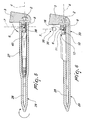
- a hinge according to the present invention comprises a lug 2, which can be connected for example to a front 3 of a frame for eyeglasses and in the illustrated embodiment lies substantially at right angles to the plane of said front that contains the lenses; the lug 2 is extended along a first longitudinal axis, designated by the reference numeral 4.
- first substantially spherical seat 5 which is connected, by means of a duct 8, to a second seat 6; the first and second seats are open at one of their ends, in that they can be accessed from the outside of the lug 2.
- the second seat 6 is substantially cylindrical and is arranged along a second longitudinal axis 7, which is substantially perpendicular to the first longitudinal axis 4 of the lug 2.
- the first seat 5 and the second seat 6 are mutually connected by means of a duct 8, which is curved or straight and has a third longitudinal axis 9 that is inclined with respect to the first longitudinal axis 4 of the lug 2.
- the lug 2 further has an end slot 10, provided along the first longitudinal axis 4, which forms two shoulders 11 a and 11b between which the first seat 5, the duct 8 and the second seat 6 act, the distance between said pair of shoulders being less than a diameter of the first seat 5.
- Each one of said shoulders forms, in turn, a first upper surface 12a and a second front surface 12b.
- the lug 2 further comprises, on the opposite side with respect to the second seat 6, a contoured surface 13, which is closed and forms, proximate to the bottom of the second seat 6, a third lower surface 14, which is substantially flat and is blended with a fourth curved surface 15.
- the first seat 5 and the duct 8 are formed in an upper region at said fourth surface.
- the third lower surface 14 is inclined with respect to the first upper surface 12a, so as to diverge from it away from the second seat 6.
- An abutment tooth 16 is further provided on the lug 2, at each one of the first upper surfaces 12a; its function is described in greater detail hereinafter, and it protrudes from the first upper surface 12a proximate to the second seat 6 and is directed toward the second front surface 12b.
- the hinge 1 further comprises a connecting element 17, which is substantially elongated and supports a spherical head 18 at a first end, said head having such dimensions that it can be accommodated within the first seat 5 and can abut against the lateral surface of said first seat.
- the head 18 is connected, by means of a stem 40, to a body 19, which is shaped for example like a parallelepiped and forms fifth lateral surfaces 20, which are for example parallel to each other.
- the connecting element 17 is completed by an elongated region 21, which is substantially rod-shaped and supports coaxially elastic means constituted by an elastic element 22, constituted for example by a spring, which is interposed between a first abutment 23, formed at the end of the connecting element 17 that lies opposite the end that supports the head 18, and a locking element 24.
- said first abutment can be obtained by plastically deforming said end so as to obtain a wider region suitable to prevent the elastic element 22 from sliding off.
- the locking element 24 is supported so that it can slide by the connecting element 17 by way of the elongated region 21; the action of the elastic element 22 is directed so as to contrast said sliding, pushing the locking element against the body 19.
- Said locking element can be constituted for example by a ring that supports a plurality of longitudinal fins 25 that have a limited elastic deformability and also are each provided with a narrower central region 26, so as to form, along the entire outside perimeter of the locking element, a region that has a reduced diameter.
- the hinge 1 further comprises a containment element 27, which is elongated and is suitable to be connected to a metallic core 28 of a temple 29, for example of the monobloc type, for frames of eyeglasses.
- a cavity 30 is formed longitudinally inside the containment element or body 27, is open at a first end 31 of the containment element or body 27, and is suitable to contain at least partially the connecting element 17, the locking element 24 and the elastic element 22 assembled as shown above.
- a second abutment 33 is formed along the internal surface 32 of the cavity 30 and is constituted for example by a protrusion that is extended toward the inside of said cavity and is suitable to be accommodated inside the narrower region 26 of the longitudinal fins 25, defining the position of the locking element 24 with respect to the containment element 27.
- the cavity 30 has, at its open end, slots 34 that are formed on a portion of the internal surface 32 and are contoured so as to engage against at least one portion of the fifth lateral surfaces 20 of the body 19, so as to prevent, once the connecting element 17 is inserted in the cavity 30, rotations thereof with respect to said cavity.
- the hinge 1 further comprises a plug 35, which is for example made of plastics and substantially cylindrical; said plug is suitable to be accommodated detachably within the second seat 6 so as to prevent axial sliding of the head 18 and is provided with one or more circumferential grooves or slots 36, which are formed on its lateral surface and are suitable to facilitate the extraction of the plug.
- a plug 35 which is for example made of plastics and substantially cylindrical; said plug is suitable to be accommodated detachably within the second seat 6 so as to prevent axial sliding of the head 18 and is provided with one or more circumferential grooves or slots 36, which are formed on its lateral surface and are suitable to facilitate the extraction of the plug.
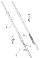
- the temple 29 is subjected to a translational motion by imparting a force F along an axis designated by the reference numeral 37, so that the head 18 moves along the duct 8 until it is accommodated in the first seat 5, reaching the configuration shown in Figure 4 , in which the temple 29 is spaced from the front 3.
- the assembly of the hinge 1 then entails imparting a rotation of approximately 90°, centered on the head 18, to the temple 29, said head remaining always accommodated inside the first seat 5, so as to move away from the front 3, until it assumes a position that is substantially perpendicular with respect to said front, as shown in Figure 5 .
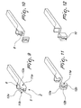
- Another step of assembly then consists in turning the temple 29 about its own longitudinal axis until the final configuration, shown in Figure 6 , is reached.
- the second seat 6 is closed removably by inserting the plug 35, so as to limit the axial sliding of the head 18.
- the rotation of the temple 29 about its own longitudinal axis is rendered necessary by the fact that since the containment element 27 is arranged at a certain distance from the end 39 of the temple 29 for aesthetic and functional reasons, it would not be possible to perform the first step of assembly, i.e., the insertion of the head 18 in the second seat 6, without arranging the temple 29 adjacent to the front 3 in a position that is rotated about its own longitudinal axis, in order to avoid interferences between said temple and the lug 2.
- the plug 35 can be made of plastic material, so as to utilize the elasticity of said material, while all the other elements can be conveniently made of metal.
- the operation of the hinge according to the invention is therefore immediately understandable, since the temple 29 can rotate freely with respect to the front 3 about the fulcrum constituted by the spherical head 18 and the first seat 5, allowing to open and close the frame for eyeglasses according to the needs of the user.
- the surface 38 of the containment element 27 remains in contact with the lug 2, adhering respectively to the second front surface 12b and to the first upper surface 12a, and vice versa.
- the containment element is at a variable distance from said point, as a consequence of the action applied by the first upper surface 12a and by the second front surface 12b, which depends on the profile of said surfaces, to the surface 38.
- the configuration of the contoured surface 13 of the lug 2 further allows an opening that is wider than the opening for normal use, the breadth of said opening being controlled by way of the inclination of the third lateral surface 14, which acts as an abutment for the end 39 of the temple, so as to make it easier to put on the frame.
- the tooth abutment 16 constitutes an abutment for the correct positioning of the temple 29.
- the presence of the plug 35 further constitutes a hindrance to any accidental escape of the head 18 from the first seat 5, thus preventing any disarticulation of the hinge 1.
- the grooves 36 provided on the lateral surface of the plug 35 allow, if it becomes necessary to replace a temple or the front, to extract said plug, possibly with the aid of suitable tools, so as to allow to separate the temple 29 and the front 3 according to a method that is the reverse of the one described above for assembly.
- the elastic hinge according to the invention ensures a safe coupling, since disarticulation of the system is prevented.
- Another object achieved by the invention is the assurance of interchangeability of the temples of a frame, allowing quick disassembly of the elastic hinge when necessary.
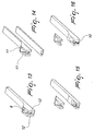
- Said second embodiment differs from the first one in that the cavity 130, designed to accommodate the coupling element 117, is formed directly inside the temple 129.
- the assembly of the invention according to said second embodiment is similar to the one described above for the first embodiment, except for the rotation about the longitudinal axis of the temple, which in this second case is not provided because it is not necessary.
Landscapes
- Physics & Mathematics (AREA)
- Health & Medical Sciences (AREA)
- General Physics & Mathematics (AREA)
- Ophthalmology & Optometry (AREA)
- Optics & Photonics (AREA)
- Pivots And Pivotal Connections (AREA)
- Eyeglasses (AREA)
Claims (12)
- Ein Federscharnier, insbesondere für einteilige Bügel, das Folgendes umfasst:einen Vorsprung (2), der mit einer Vorderseite (3) eines Rahmens für eine Brille verbunden werden kann, so dass er aus der Vorderseite (3) des Rahmens herausragt, wobei sich der Vorsprung entlang einer Längsachse (4) erstreckt und einen ersten, kugelförmigen Sitz (5) hat, der mit einem zweiten, zylindrischen Sitz (6) verbunden ist, welcher eine Achse (7) hat, die im Wesentlichen senkrecht zu der Längsachse (4) des Vorsprungs (2) ist,ein im Wesentlichen verlängertes Verbindungselement (17), das an einem ersten Ende einen kugelförmigen Kopf (18) trägt, wobei die Maße des Kopfs (18) derart sind, dass er in dem ersten Sitz (5) untergebracht werden kann und gegen die seitliche Oberfläche des ersten Sitzes (5) anstoßen kann, wobei das Verbindungselement (17) einen verlängerten Bereich (21) umfasst, der im Wesentlichen stabförmig ist und koaxial elastische Mittel trägt, die in einem elastischen Element (22) bestehen, welches zwischen einem ersten Widerlager (23) angeordnet ist, das an einem Ende des Verbindungselements (17) geformt ist, welches dem Ende gegenüberliegt, das den Kopf (18) trägt, und einem Verriegelungselement (24), das verschiebbar von dem Verbindungselement (17) getragen wird, und zwar durch den verlängerten Bereich (21),ein verlängertes Behälterelement (27), das ausgebildet ist, um mit einem Bügel für einen Rahmen für eine Brille verbunden oder direkt darin geformt zu sein, wobei ein Hohlraum (30) in Längsrichtung innerhalb des Behälterelements (27) geformt ist, wobei der Hohlraum (30) an einem ersten Ende (31) des Behälterelements (27) offen und geeignet ist, das Verbindungselement (17), das Verriegelungselement (24) und das elastische Element (22) zumindest teilweise aufzunehmen,wobei der kugelförmige Kopf (18) sich axial in Bezug zum Behälterelement (27) gegen das elastische Element (22) bewegen kann,dadurch gekennzeichnet, dass der kugelförmige Kopf (18) vollständig aus dem Hohlraum (30) herausragt und der erste, kugelförmige Sitz (5) über eine erste Führung (8), die im Verhältnis zur Längsachse (4) des Vorsprungs (2) geneigt ist, mit dem zweiten, zylindrischen, Sitz (6) verbunden ist, wobei der kugelförmige Kopf (18) in den zweiten Sitz (6) einsetzbar ist, von wo er in einer Translationsbewegung innerhalb der geneigten Führung (8) zum ersten, kugelförmigen Sitz (5) hin bewegt werden kann, wobei das Scharnier weiter einen Stöpsel (35) umfasst, der lösbar in den zweiten Sitz (6) einsetzbar ist, um eine axiale Verschiebung des Kopfs (18) zu verhindern.
- Das Federscharnier gemäß Anspruch 1, dadurch gekennzeichnet, dass der Vorsprung (2) einen Endschlitz (10) hat, der entlang der Längsachse (4) geformt ist und zwei Schultern (11a, 11b) bildet, zwischen denen der erste Sitz (5), der zweite Sitz (6) und die Führung (8) angeordnet sind, wobei der Abstand zwischen dem Paar von Schultern (11a, 11b) kleiner ist als ein Durchmesser des ersten Sitzes (5).
- Das Federscharnier gemäß Anspruch 2, dadurch gekennzeichnet, dass jede der Schultern (11a, 11b) an dem Vorsprung (2) eine erste, obere Oberfläche (12a) und eine zweite, vordere Oberfläche (12b) bildet, wobei der Vorsprung (2) weiter, an der Seite gegenüber vom zweiten Sitz (6), eine geschlossene konturierte Oberfläche (13) umfasst, welche, nahe dem Boden des zweiten Sitzes (6), eine dritte, im Wesentlichen flache, untere Oberfläche (14) bildet, die in eine vierte, gekrümmte Oberfläche (15) übergeht, an welcher der erste Sitz (5) und die Führung (8) in einem oberen Bereich geformt sind.
- Das Federscharnier gemäß Anspruch 3, dadurch gekennzeichnet, dass die dritte untere Oberfläche (14) im Verhältnis zu der ersten oberen Oberfläche (12a) geneigt ist und von ihr in der Richtung abzweigt, die dem zweiten Sitz (6) entgegengesetzt ist.
- Das Federscharnier gemäß Anspruch 4, dadurch gekennzeichnet, dass ein Widerlagerzahn (16) an dem Vorsprung (2) an jeder der ersten oberen Oberflächen (12a) geformt ist, aus der entsprechenden ersten, oberen Oberfläche (12a), nahe dem zweiten Sitz (6), herausragt und zu der zweiten, vorderen Oberfläche (12b) hin gerichtet ist.
- Das Federscharnier (1) gemäß einem oder mehreren der obigen Ansprüche, dadurch gekennzeichnet, dass der kugelförmige Kopf (18), über einen Schaft (40), mit einem Körper (19) verbunden ist, der Teil des Verbindungselements (17) ist und fünfte seitliche Oberflächen (20) bildet, die zueinander parallel sind, wobei der verlängerte Bereich (21) an einem Ende mit dem Körper (19) verbunden ist.
- Das Federscharnier (1) gemäß Anspruch 6, dadurch gekennzeichnet, dass das Verriegelungselement (24) in einem Ring besteht, der eine Vielzahl von Längsrippen (25) trägt, welche eine begrenzte elastische Verformbarkeit haben, wobei jede der Rippen (25) einen schmaleren zentralen Bereich (26) hat, wobei die zentralen Bereiche (26) einen Bereich mit einem reduzierten Durchmesser entlang einem äußeren Umfang des Verriegelungselements (24) bilden.
- Das Federscharnier (1) gemäß Anspruch 7, dadurch gekennzeichnet, dass ein zweites Widerlager (33) entlang einer inneren Oberfläche (32) des Hohlraums (30) geformt ist und in einem Vorsprung besteht, der sich zur Innenseite des Hohlraums (30) hin erstreckt und in dem schmaleren Bereich der Längsrippen (25) aufgenommen werden kann.
- Das Federscharnier (1) gemäß Anspruch 8, dadurch gekennzeichnet, dass der Hohlraum (30) an dem offenen Ende einen oder mehrere Schlitze (34) hat, die an einem Abschnitt der inneren Oberfläche (32) geformt sind und so konturiert sind, dass sie mindestens einen Abschnitt der fünften seitlichen Oberflächen (20) halten.
- Das Federscharnier gemäß einem oder mehreren der obigen Ansprüche, dadurch gekennzeichnet, dass der Stöpsel (35) mit einer/m oder mehreren Ringnuten oder Schlitzen (36) versehen ist, die an seiner seitlichen Oberfläche geformt sind.
- Das Federscharnier gemäß einem oder mehreren der obigen Ansprüche, dadurch gekennzeichnet, dass der Stöpsel (36) aus Kunststoffmaterial besteht.
- Ein Verfahren zum Zusammenbau eines Scharniers gemäß einem beliebigen der obigen Ansprüche, das folgende Schritte umfasst:a. Platzierung eines Bügels (29), der mit dem verlängerten Behälterelement (27) verbunden ist, im Wesentlichen angrenzend zu der Vorderseite (3) eines Rahmens für eine Brille, verbunden mit dem Vorsprung (2),b. Einsetzen, entlang einer Achse (4), die in Längsrichtung zu dem Bügel (29) verläuft, des kugelförmigen Kopfs (18) des Scharniers in den zweiten Sitz (6) des Vorsprungs (2), wobei der Vorsprung (2) in einem rechten Winkel aus der Vorderseite (3) herausragt,c. eine Translationsbewegung, an der Seite, die der Vorderseite (3) gegenüberliegt, des kugelförmigen Kopfs (18) innerhalb der geneigten Führung (8), die in dem Vorsprung (2) bereitgestellt ist,d. Aufnahme des kugelförmigen Kopfs (18) in dem ersten, kugelförmigen Sitz (5), der in dem Vorsprung (2) geformt ist,e. Drehung des Bügels (29) fort von der Vorderseite (3),f. Drehung des Bügels (29) um seine eigene Längsachse,g. Schließen des zweiten Sitzes (6) mit dem Stöpsel (35), um so die Bewegung des Kopfes (18) in einer axialen Richtung zu blockieren.
Applications Claiming Priority (2)
| Application Number | Priority Date | Filing Date | Title |
|---|---|---|---|
| ITTV20030139 | 2003-10-13 | ||
| ITTV20030139 ITTV20030139A1 (it) | 2003-10-13 | 2003-10-13 | Cerniera elastica particolarmente per aste monoblocco. |
Publications (2)
| Publication Number | Publication Date |
|---|---|
| EP1524547A1 EP1524547A1 (de) | 2005-04-20 |
| EP1524547B1 true EP1524547B1 (de) | 2012-11-14 |
Family
ID=34362457
Family Applications (1)
| Application Number | Title | Priority Date | Filing Date |
|---|---|---|---|
| EP04020767A Expired - Lifetime EP1524547B1 (de) | 2003-10-13 | 2004-09-01 | Federscharnier insbesondere für einstückige Bügel |
Country Status (3)
| Country | Link |
|---|---|
| EP (1) | EP1524547B1 (de) |
| CN (1) | CN100410730C (de) |
| IT (1) | ITTV20030139A1 (de) |
Families Citing this family (8)
| Publication number | Priority date | Publication date | Assignee | Title |
|---|---|---|---|---|
| ITUD20070059A1 (it) * | 2007-03-22 | 2008-09-23 | Visottica Ind Spa | Cerniera elastica e regolabile per occhiali |
| CN101875167B (zh) * | 2009-04-30 | 2012-11-21 | 浙江康华眼镜有限公司 | 铰链弹簧轴自动组装机 |
| ITTV20130156A1 (it) * | 2013-10-03 | 2015-04-04 | Ideal Srl | Montatura per occhiali |
| DE102016007403B4 (de) | 2016-06-17 | 2018-08-30 | Aurélien Mierswa | Gelenk als Verbindungsteil zwischen einer Brillenfront einer Brille und ihren Bügeln |
| IT201900012243A1 (it) * | 2019-07-18 | 2021-01-18 | Luxottica Srl | Occhiale con cerniera per astina semplificata. |
| DE102020112407B4 (de) * | 2020-05-07 | 2021-11-18 | Mykita Studio Gmbh | Brillengelenk |
| IT202100032129A1 (it) * | 2021-12-24 | 2023-06-24 | Paolo Todoverto | Snodo a cavita' sferica per astina elastica intercambiabile di occhiale e suo metodo di assemblaggio |
| AT17866U1 (de) * | 2022-05-03 | 2023-05-15 | Redtenbacher Praez Ges M B H | Federscharnier für eine Brille |
Citations (1)
| Publication number | Priority date | Publication date | Assignee | Title |
|---|---|---|---|---|
| EP0207190A2 (de) * | 1985-07-05 | 1987-01-07 | Rino Sartor | Bügelvorrichtung für Brillengestelle und ähnliches |
Family Cites Families (5)
| Publication number | Priority date | Publication date | Assignee | Title |
|---|---|---|---|---|
| FR2654845B1 (fr) * | 1989-11-21 | 1992-03-13 | Essilor Int | Charniere elastique. |
| US5187504A (en) * | 1991-05-10 | 1993-02-16 | David Huang | Eyeglass frame having hollow adjustable connector |
| FR2690760A1 (fr) * | 1992-05-04 | 1993-11-05 | Essilor Int | Charnière élastique sans vis apparente. |
| DE4339517C1 (de) * | 1993-11-19 | 1995-05-18 | Heinrich Uphoff | Brillengestell mit Bügelgelenk |
| ITPD20010190A1 (it) * | 2001-07-26 | 2003-01-26 | Prisma Srl | Cerniera elastica per occhiali |
-
2003
- 2003-10-13 IT ITTV20030139 patent/ITTV20030139A1/it unknown
-
2004
- 2004-09-01 EP EP04020767A patent/EP1524547B1/de not_active Expired - Lifetime
- 2004-10-11 CN CNB2004100856206A patent/CN100410730C/zh not_active Expired - Fee Related
Patent Citations (1)
| Publication number | Priority date | Publication date | Assignee | Title |
|---|---|---|---|---|
| EP0207190A2 (de) * | 1985-07-05 | 1987-01-07 | Rino Sartor | Bügelvorrichtung für Brillengestelle und ähnliches |
Also Published As
| Publication number | Publication date |
|---|---|
| EP1524547A1 (de) | 2005-04-20 |
| ITTV20030139A1 (it) | 2005-04-14 |
| CN100410730C (zh) | 2008-08-13 |
| CN1607419A (zh) | 2005-04-20 |
Similar Documents
| Publication | Publication Date | Title |
|---|---|---|
| US4244081A (en) | Hinge for spectacles | |
| KR100232262B1 (ko) | 접는 안경 | |
| US8371692B2 (en) | Pinless hinge for eyewear | |
| US6050686A (en) | Dismountable elastic spectacle hinge | |
| EP1524547B1 (de) | Federscharnier insbesondere für einstückige Bügel | |
| CN106802492B (zh) | 用于眼镜框架的弹性铰链及其安装程序 | |
| CN110007481B (zh) | 用于眼镜框架的弹性铰链以及用于处理该铰链铰接螺丝的方法 | |
| US11275258B2 (en) | Spectacle frame with temple orientation according to a plurality of planes | |
| US10642065B2 (en) | Elastic hinge for eyeglasses | |
| MXPA03003583A (es) | Anteojos con vidrios intercambiables. | |
| CN110221453A (zh) | 具有接合在托架本体上的锁定夹的、用于眼镜架镜腿的弹性铰链 | |
| EP1279991A1 (de) | Federscharnier für Brillen | |
| CN204116734U (zh) | 眼镜架的连接结构 | |
| KR20190026865A (ko) | 안경 프레임의 구성 부품을 부착하기 위한 부착 장치 및 상기 부착 장치를 포함하는 안경 | |
| JPS60146218A (ja) | 眼鏡フレームおよびこれに取り付ける眼鏡フロント用支持構造体 | |
| US6390620B1 (en) | Hinge wing with flexing device for temples of eyeglasses | |
| US20190011726A1 (en) | Hinge for eyeglasses | |
| HK1076156A (en) | Elastic hinge particularly for monobloc temples | |
| KR20000068576A (ko) | 신축성을 갖는 안경테 측면부의 경첩 | |
| US7452072B2 (en) | Method for manufacturing a resilient hinge device for spectacles, device obtained by the method, and spectacles comprising said device | |
| EP1482350A1 (de) | Federscharnier für Brillen | |
| JP5709116B1 (ja) | 蝶番構造 | |
| CN217181357U (zh) | 一种方便拆换镜片的镜框 | |
| JPH0648485Y2 (ja) | 眼鏡のテンプル | |
| KR102214976B1 (ko) | 안경테와 안경다리의 연결장치 |
Legal Events
| Date | Code | Title | Description |
|---|---|---|---|
| PUAI | Public reference made under article 153(3) epc to a published international application that has entered the european phase |
Free format text: ORIGINAL CODE: 0009012 |
|
| AK | Designated contracting states |
Kind code of ref document: A1 Designated state(s): AT BE BG CH CY CZ DE DK EE ES FI FR GB GR HU IE IT LI LU MC NL PL PT RO SE SI SK TR |
|
| AX | Request for extension of the european patent |
Extension state: AL HR LT LV MK |
|
| RAP1 | Party data changed (applicant data changed or rights of an application transferred) |
Owner name: VISOTTICA INDUSTRIE S.P.A. |
|
| 17P | Request for examination filed |
Effective date: 20050906 |
|
| REG | Reference to a national code |
Ref country code: HK Ref legal event code: DE Ref document number: 1076156 Country of ref document: HK |
|
| AKX | Designation fees paid |
Designated state(s): AT DE FR GB IT |
|
| 17Q | First examination report despatched |
Effective date: 20070917 |
|
| REG | Reference to a national code |
Ref country code: HK Ref legal event code: WD Ref document number: 1076156 Country of ref document: HK |
|
| GRAP | Despatch of communication of intention to grant a patent |
Free format text: ORIGINAL CODE: EPIDOSNIGR1 |
|
| GRAS | Grant fee paid |
Free format text: ORIGINAL CODE: EPIDOSNIGR3 |
|
| GRAA | (expected) grant |
Free format text: ORIGINAL CODE: 0009210 |
|
| AK | Designated contracting states |
Kind code of ref document: B1 Designated state(s): AT DE FR GB IT |
|
| REG | Reference to a national code |
Ref country code: GB Ref legal event code: FG4D |
|
| REG | Reference to a national code |
Ref country code: AT Ref legal event code: REF Ref document number: 584274 Country of ref document: AT Kind code of ref document: T Effective date: 20121115 |
|
| REG | Reference to a national code |
Ref country code: DE Ref legal event code: R096 Ref document number: 602004040008 Country of ref document: DE Effective date: 20130110 |
|
| REG | Reference to a national code |
Ref country code: AT Ref legal event code: MK05 Ref document number: 584274 Country of ref document: AT Kind code of ref document: T Effective date: 20121114 |
|
| PG25 | Lapsed in a contracting state [announced via postgrant information from national office to epo] |
Ref country code: AT Free format text: LAPSE BECAUSE OF FAILURE TO SUBMIT A TRANSLATION OF THE DESCRIPTION OR TO PAY THE FEE WITHIN THE PRESCRIBED TIME-LIMIT Effective date: 20121114 |
|
| PLBE | No opposition filed within time limit |
Free format text: ORIGINAL CODE: 0009261 |
|
| STAA | Information on the status of an ep patent application or granted ep patent |
Free format text: STATUS: NO OPPOSITION FILED WITHIN TIME LIMIT |
|
| 26N | No opposition filed |
Effective date: 20130815 |
|
| REG | Reference to a national code |
Ref country code: DE Ref legal event code: R097 Ref document number: 602004040008 Country of ref document: DE Effective date: 20130815 |
|
| GBPC | Gb: european patent ceased through non-payment of renewal fee |
Effective date: 20130901 |
|
| REG | Reference to a national code |
Ref country code: DE Ref legal event code: R119 Ref document number: 602004040008 Country of ref document: DE Effective date: 20140401 |
|
| REG | Reference to a national code |
Ref country code: FR Ref legal event code: ST Effective date: 20140530 |
|
| PG25 | Lapsed in a contracting state [announced via postgrant information from national office to epo] |
Ref country code: GB Free format text: LAPSE BECAUSE OF NON-PAYMENT OF DUE FEES Effective date: 20130901 |
|
| PG25 | Lapsed in a contracting state [announced via postgrant information from national office to epo] |
Ref country code: FR Free format text: LAPSE BECAUSE OF NON-PAYMENT OF DUE FEES Effective date: 20130930 Ref country code: DE Free format text: LAPSE BECAUSE OF NON-PAYMENT OF DUE FEES Effective date: 20140401 |
|
| PGFP | Annual fee paid to national office [announced via postgrant information from national office to epo] |
Ref country code: IT Payment date: 20180921 Year of fee payment: 15 |
|
| PG25 | Lapsed in a contracting state [announced via postgrant information from national office to epo] |
Ref country code: IT Free format text: LAPSE BECAUSE OF NON-PAYMENT OF DUE FEES Effective date: 20190901 |