EP1524546A1 - Scannersystem mit vor Ort auswechselbarem Lasermodul - Google Patents
Scannersystem mit vor Ort auswechselbarem Lasermodul Download PDFInfo
- Publication number
- EP1524546A1 EP1524546A1 EP04105003A EP04105003A EP1524546A1 EP 1524546 A1 EP1524546 A1 EP 1524546A1 EP 04105003 A EP04105003 A EP 04105003A EP 04105003 A EP04105003 A EP 04105003A EP 1524546 A1 EP1524546 A1 EP 1524546A1
- Authority
- EP
- European Patent Office
- Prior art keywords
- lens
- laser
- media
- exposure
- subsystem
- Prior art date
- Legal status (The legal status is an assumption and is not a legal conclusion. Google has not performed a legal analysis and makes no representation as to the accuracy of the status listed.)
- Withdrawn
Links
- 230000003287 optical effect Effects 0.000 claims abstract description 26
- 238000007639 printing Methods 0.000 claims description 30
- 238000007493 shaping process Methods 0.000 claims description 22
- 238000013461 design Methods 0.000 abstract description 17
- 238000012937 correction Methods 0.000 abstract description 5
- 238000000034 method Methods 0.000 description 8
- 201000009310 astigmatism Diseases 0.000 description 6
- 239000000463 material Substances 0.000 description 5
- 230000008569 process Effects 0.000 description 5
- 230000008901 benefit Effects 0.000 description 4
- 239000011521 glass Substances 0.000 description 4
- 230000004075 alteration Effects 0.000 description 3
- 239000011248 coating agent Substances 0.000 description 3
- 238000000576 coating method Methods 0.000 description 3
- 239000000839 emulsion Substances 0.000 description 3
- 210000001624 hip Anatomy 0.000 description 3
- 238000003384 imaging method Methods 0.000 description 3
- 239000004065 semiconductor Substances 0.000 description 3
- 239000000758 substrate Substances 0.000 description 3
- 238000002834 transmittance Methods 0.000 description 3
- 238000010586 diagram Methods 0.000 description 2
- 230000000694 effects Effects 0.000 description 2
- 239000000976 ink Substances 0.000 description 2
- 238000007645 offset printing Methods 0.000 description 2
- 230000035945 sensitivity Effects 0.000 description 2
- XAGFODPZIPBFFR-UHFFFAOYSA-N aluminium Chemical compound [Al] XAGFODPZIPBFFR-UHFFFAOYSA-N 0.000 description 1
- 229910052782 aluminium Inorganic materials 0.000 description 1
- 238000013459 approach Methods 0.000 description 1
- 230000005540 biological transmission Effects 0.000 description 1
- 230000015556 catabolic process Effects 0.000 description 1
- 230000008859 change Effects 0.000 description 1
- 238000010276 construction Methods 0.000 description 1
- 238000006731 degradation reaction Methods 0.000 description 1
- 230000001419 dependent effect Effects 0.000 description 1
- 239000006185 dispersion Substances 0.000 description 1
- 239000003292 glue Substances 0.000 description 1
- 238000009434 installation Methods 0.000 description 1
- 230000007774 longterm Effects 0.000 description 1
- 238000004519 manufacturing process Methods 0.000 description 1
- 230000007246 mechanism Effects 0.000 description 1
- 230000008520 organization Effects 0.000 description 1
- 229920000728 polyester Polymers 0.000 description 1
- 239000002243 precursor Substances 0.000 description 1
- 229910000679 solder Inorganic materials 0.000 description 1
- 238000001228 spectrum Methods 0.000 description 1
- 238000012546 transfer Methods 0.000 description 1
Images

Classifications
-
- B—PERFORMING OPERATIONS; TRANSPORTING
- B41—PRINTING; LINING MACHINES; TYPEWRITERS; STAMPS
- B41J—TYPEWRITERS; SELECTIVE PRINTING MECHANISMS, i.e. MECHANISMS PRINTING OTHERWISE THAN FROM A FORME; CORRECTION OF TYPOGRAPHICAL ERRORS
- B41J2/00—Typewriters or selective printing mechanisms characterised by the printing or marking process for which they are designed
- B41J2/435—Typewriters or selective printing mechanisms characterised by the printing or marking process for which they are designed characterised by selective application of radiation to a printing material or impression-transfer material
- B41J2/47—Typewriters or selective printing mechanisms characterised by the printing or marking process for which they are designed characterised by selective application of radiation to a printing material or impression-transfer material using the combination of scanning and modulation of light
- B41J2/471—Typewriters or selective printing mechanisms characterised by the printing or marking process for which they are designed characterised by selective application of radiation to a printing material or impression-transfer material using the combination of scanning and modulation of light using dot sequential main scanning by means of a light deflector, e.g. a rotating polygonal mirror
Definitions
- the present invention relates to a laser based media exposure system. More specifically the invention is related to exposure systems that are used to expose printing plates or printing plate pre-cursors.
- Imagesetters and platesetters are used to expose media that are used in offset printing systems. Imagesetters are typically used to expose the film that is then used to make the plates for the printing system. Platesetters are used to directly expose the plates.
- plates are typically large substrates that have been coated with photosensitive or thermally-sensitive material layers, referred to as the emulsion.
- the substrates are fabricated from aluminum, although organic substrates, such as polyester or paper, are also available for smaller runs.
- Computer-to-plate printing systems are used to render digitally stored print content onto these printing plates.
- a computer system is used to drive an imaging engine of the platesetter.
- the plate is fixed to the outside or inside of a drum or held on a flat bed and then scanned with a modulated laser source in a raster fashion.
- the imaging engine selectively exposes the emulsion that is coated on the plates with the desired image. After this exposure, the emulsion is developed so that, during the printing process, inks will selectively adhere to the plate's surface to transfer the ink to the print medium.
- the imaging engine exposure systems of these platesetters and/or imagesetters must have highly optimized and calibrated optical systems.
- a light dot generated typically by a laser, is used to expose the printing media. Its size at the image plane or the printing media must be well controlled over the life of the machine and over the entire scan in order to ensure that the system's performance or resolution does not degrade and is constant across the width of the plate.
- a specially-designed beam shaping subsystem is used to collimate the beam from the laser source. The collimated beam is then provided to a scanning subsystem that scans the beam over the printing media.
- the beam shaping sub-systems tend to be relatively large and inflexible. They are typically designed and optimized in order to generate highly collimated beams from the laser. Typically, semiconductor lasers are used in which the beams are highly diverging, challenging the design of the optics. Thus, in order to collimate these beams, relatively large optical bench-type systems are specially manufactured and calibrated in order to generate the desired beam characteristics.
- One current design uses a fixed focal length collimator in order to collimate the output of a 30 milliWatt violet laser diode in combination with a cemented cylindrical achromatic lens-doublet, which provides for axial color correction with changing diode wavelength over the range of 400-410 nm.
- the current design of the pre-scan optics does not offer field modularity on a low cost base. If the laser diode has to be replaced, the entire optics bench has to be exchanged since any slight misalignment of the diode-collimator distance would result in an astigmatic focus shift and degrade the image quality. Besides, in order to compensate for axial focus shift as a result of laser diode wavelength changes, a sophisticated color corrected design for the pre-scan optics was used.
- the present invention is directed to a design for the pre-scan optics, which offers the possibility of low cost field modularity by replacing a rather inexpensive optical sub-module inside the pre-scan optics instead of the entire optics bench.
- the invention features a media exposure system. It comprises a field-replaceable laser source sub-system that generates an exposure beam. A beam shaping sub-system then shapes this exposure beam. Finally, a scanning sub-system scans the exposure beam over the printing media.
- the advantage is that, in the case of a laser diode failure, only the laser source together with a lens must be replaced. Moreover, the lens can be an inexpensive off-the-shelf, commercially available, element.
- the beam shaping sub-system which collimates the beam from the laser, can be maintained in the unit, reducing the cost for servicing such a failure.
- the field-replaceable laser source sub-system comprises a diode laser and a source lens.
- the source lens is a low-cost aspheric molded glass lens, which serves to pre-collimate but not to fully collimate the beam emanating from the laser diode.
- the beam shaping sub-system comprises a cylindrical lens for focusing the exposure beam along one axis.
- the beam shaping sub-system further comprises a singlet lens and a doublet lens for generating a collimated beam in combination with the cylindrical lens in one implementation.
- some lens elements are provided on movable stages.
- a singlet lens stage is provided for the singlet lens and a cylindrical lens stage is provided for the cylindrical lens in order to adjust their position along the optical axis.
- This further allows the system to adapt to the fact that different laser diodes operate at slightly different wavelengths. That is, it is typical that the specification for the laser diodes allows for some variability in their wavelength, such as between 400 and 410 nanometers (nm). Adding this degree of adjustability allows for the system to collimate beams having slightly different wavelengths to compensate for the dispersiveness of the optics used in the system.
- the scanning sub-system in the preferred embodiment comprises a scanning device, such as a rotating polygon and an anamorphic post-scanning optics for relaying the exposure beam from the scanning device to the print media in the "cross-scan” dimension (y) and focusing the collimated beam onto the print media in the "in-scan” dimension (x).
- a scanning device such as a rotating polygon and an anamorphic post-scanning optics for relaying the exposure beam from the scanning device to the print media in the "cross-scan” dimension (y) and focusing the collimated beam onto the print media in the "in-scan” dimension (x).
- the invention features a media exposure system.
- This comprises a laser source sub-system that generates an exposure beam.
- a beam shaping sub-system shapes the exposure beam and includes at least one optical element stage for changing distances between the optical elements in the beam shaping sub-system and/or relative to the laser source sub-system to control the shaping of the exposure beam to compensate for changes in wavelength and alignment accuracies (e.g. distance between the diode and the aspheric lens).
- a scanning sub-system is provided that scans the exposure beam over the printing media.
- Fig. 1 shows the general organization of a platesetter or imagesetter.
- this printing media is a plate. In other examples, it can be film, which is then used to make plates for the offset printing system.
- the printing media 114 is held by a media support holder 116.
- this holder 116 is a drum. Drums are either internal or external, referring to whether the printing media is wrapped over the inside or outside of the drum. In other examples, however, the media holder 116 is a flat bed system.
- the media holder 116 and the media exposure system 110 are controlled by the platesetter/imagesetter controller 120, which controls the system's overall operation.
- an exposure beam detector 122 is provided to detect the characteristics of the exposure beam 112 during a calibration process, for example.
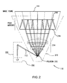
- Fig. 2 shows the media exposure system 110, according to one embodiment. It generally comprises a scanning sub-system 210. This receives an exposure beam 112 to then scan that exposure beam over the printing media 114. This printing media is located at the image plane of the optics.
- the exposure beam is scanned using a polygon 212.
- This is a multi-sided reflective instrument that spins in order to scan the exposure beam 112 over the printing media 114 at the image plane.
- Post polygon optics 214 are further provided to focus the exposure beam down onto the image plane 214.
- Fold mirrors 216 and 218 are provided to set the path length and to guide the exposure beam to the printing media.
- the exposure beam 112 is generated by a field-replaceable laser source sub-system 220.
- This typically includes a semiconductor laser that generates a relatively short wavelength beam, such as a beam having a wavelength of less than 500 nanometers (nm).
- the wavelength is between 400 and 410 nm, in the violet region of the spectrum.
- This beam is then provided to a beam shaping sub-system 222.
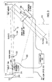
- Fig. 3 shows the field replaceable laser source sub-system 220 and the beam shaping sub-system 222, according to the preferred embodiment.
- a semiconductor diode laser chip 310 is provided on a diode laser submount 312. This provides a mechanism for attaching the diode laser 310 onto an optics bed 314 that provides mechanical rigidity and stability to and between the field-replaceable laser source sub-system 220 and the beam shaping sub-system 222.
- a source lens 316 is further provided on the diode laser submount 312. This lens begins the process of collimating the beam from the diode laser 310.
- diode lasers will generate a beam with a relatively high aspect ratio that has different divergence angles along each of the x and y axes, which are defined as perpendicular to the optical axis or parallel to the direction of light propagation.
- the y axis is perpendicular to the bed 314, and the x axis is parallel to the bed 314.
- the collimating lens 316 is necessary. In typical conventional designs a fixed focal length collimating lens is used to collimate the beam in both the x and y axes.
- This lens has to be color corrected in order to work properly for different laser diode wavelengths and has to be corrected for high order spherical aberrations which would occur because of the high numerical aperture (NA) output beam of the laser diode in at least one axis (NA > 0.2).
- NA numerical aperture
- the divergence angle of the laser diode output beam is directly related to diameter of the waist of the beam at the emitter of the diode.
- the above described diode divergence parameters lead to FWHM diameters of the beam waist at the emitter of about 0.5 micron in x and about 1.2 micron in y.
- Those beam waists define the dimension of the "object" and are relayed by the optics to an image on the printing media.
- the spot-size in the image plane 114 therefore depends on the optical magnification of the relay optics. So, in order to achieve a symmetric circular spot in the image plane an anamorphic optical relay system is required that provides different optical magnifications in the x- and the y-directions.
- an optical magnification factor m x of about 30 is necessary in the x-direction but only a magnification factor m y of 12 in the y-direction. This demands an anamorphic design of the relay optics and requires the use of cylindrical lenses or mirrors in the relay optics.
- the x-focus and y-focus (focus in the x-axis and y-axis, respectively) would overlay at the same z-position in the image plane, exactly where the printing material is positioned.
- field service would take out the old sub-assembly and replace it by a pre-aligned new sub-assembly.
- the opto-mechanical interface for example, would be realized by holes on the sub-assembly mounting plate matched position-wise with the locations of pins on the optics bed 314 so that the mechanical position of the new sub-assembly is determined.
- the pre-alignment of the distance between the diode and the collimating lens of the sub-module can be done only within a certain accuracy (usually a couple of micrometers) and any slight misalignment ( z) in the diode-collimating lens distance would immediately result in an astigmatic focus shift and dramatically deteriorate the image quality.
- the misalignment error z would be magnified by the factor (m x ) 2 in the x-direction but only by the factor (m y ) 2 in the y-direction.
- the x-focus would be shifted by z*(m x ) 2 in the z-direction away from the printing media.
- the y-focus would be shifted by z*(m y ) 2 in the z-direction away from the printing media. Since m x ⁇ > m y the x- and y-focus do not shift by the same amount leading to an astigmatic focus in the image plane which cannot be taken out by simply refocusing the printing media.
- the power is distributed over a source lens 316, a singlet lens 318, and a doublet lens 324 that are simple and inexpensive elements.
- this source lens 316 is an aspheric "off-the-shelf" lens.
- a singlet lens 318 is provided. This is held on a precision z-stage 320, which is controlled by the controller 120. This motorized z-stage 320 allows the singlet lens to be moved in the direction of the optical axis 322. This allows for the control of the collimation of the exposure beam 112.
- a doublet 324 is further provided. This provides the collimation of the exposure beam 112, and some wavelength compensation. Specifically, a doublet is a two lens arrangement designed to correct for spherical aberration and chromatic dispersion.
- the source lens 316 is used to collect and converge the exposure beam, but not fully converge it. This is accomplished through the use of the singlet lens 318 and the doublet 324 to get the required expansion.
- the optical power distribution happens first by using a low cost off-the-shelf asphere 316. By almost but not perfectly collimating the diode output with this aspherical lens a lot of "stress" is taken away from the optical design, making the beam path much more relaxed.
- the singlet lens 318 is a simple inexpensive plano-concave glass lens element. This singlet 318 has negative power and diverges the beam.
- a cemented doublet lens 324 is used next with two different glass materials for color correction.
- the doublet further collimates the divergent beam, forming an appreciably collimated beam with different diameters in the slow and fast axis resulting in an elliptical profile.
- the asphere-singlet-doublet combination represents the actual collimator for the laser diode output.
- the singlet doublet combination acts as a beam expander that expands the beam to the appropriate beam diameter and also perfectly collimates the quasi-collimated beam after the aspherical lens.
- a fold mirror 326 is further provided to direct the beam.
- a cross-scan lens 328 is provided. This is a cylinder lens that focuses the beam along one axis onto the polygon facet.
- a cross-scan cylinder lens z-stage 330 is provided to adjust the position of this cylinder lens 328 in the direction of the optical axis 332.
- This cylinder lens z-stage 330 is controlled by the controller 120, in order to control the focus position of the beam, in the axis of the cylinder lenses 328 focus, and correct for astigmatism at the final image plane.
- the residual astigmatism would be taken out by moving the cylinder lens 328. Since the cylinder lens 328 affects only the focus in the y-direction at the image plane it is possible to refocus the y-focus onto the printing media and overlay it with the already optimized position of the x-focus. As an example: In the present design, a cylinder movement of 1.7 mm shifts the y-focus in the image plane by 1.0 mm in the z-direction.
- the present invention it is possible to simulate the through-focus behavior of the system, by controlling the motorized elements using feedback from the exposure beam detector 122. It is possible to create true two-dimensional focus maps, without having to manually adjust any sensitive elements. This helps the search for the best focus at the image plane.
- this invention even allows the use of lenses that are highly dispersive and are designed to operate at other wavelengths, such as 780 nm.
- the correction is distributed over three elements. This allows for collimation in both the X and Y axes of the beam.
- a filter wheel 323 is further provided.
- the purpose of the filter wheel is to be able to control the exposure in the image plane 114 by attenuating the beam more or less depending on the plate material sensitivity.
- the filter wheel is a plan-parallel glass plate that can be rotated about the z-axis. It is equipped with a special coating where the transmittance of the coating changes continuously with the angular position of the filter wheel. The range of the transmittance goes from 100% at a zero degree filter wheel rotational angle down to almost zero transmission at an about 270 degree rotational angle which means that no power goes through the filter wheel.
- the calibration process for the replaceable diode-source-lens sub-module is straightforward. Because of the fact that it is possible to refocus misalignment errors in the diode-source lens distance (which is by far the most important alignment error because of sensitivity reasons) with the help of the motorized singlet 318 and cylinder lens 324 later in the system, it is mainly necessary to ensure that the required movement of those two lenses do not exceed the range of possible travel, which is limited by the length of the z-stages.
- the diode-source lens sub-assembly (which is a field replaceable module) is combined on a so-called "master” tool with a permanently residing singlet and doublet lens.
- the beam after the doublet is evaluated with a "Shear” plate.
- the Shear plate is an interferometric tool that provides information about the degree of collimation of a beam.
- the distance between the diode and the source lens can be judged by watching the interferometric pattern on the Shear plate screen.
- the system is equipped with a calibration device 122, which includes for example a set of gratings and photo-detectors behind.
- the grating is positioned where the media and therefore where the focus of the exposure beam is supposed to be.
- the grating is usually a few millimeters wide with typically 500-1000 line-pairs per millimeter leading to a spacing of about 10-20 micrometer, which is about the size of the beam itself. It can be realized for example by a special coating with alternating transmittance properties so that the beam when it scans over the grating is alternately transmitted or blocked by the grating. As a result the beam is modulated in intensity when it hits the photo-detector.
- the modulation depth of this modulated photo-detector signal is a measure for the spot size of the beam that scans over the grating.
- the smaller the spot size the more light intensity reaches the detector when the beam passes the gaps of the grating and therefore the bigger is the change in intensity between a blocked beam and a transmitted beam.
- the spot size in the image plane where the exposure medium and therefore the calibration grating and detector sits would be too large, leading to an almost un-modulated detector signal. Best focus is determined by the highest achievable modulation depth.
- field service for example would be able to optimize the x- and y-focus by moving as explained above the singlet and cylinder in the pre-scan optics, judging the success of their efforts in real time by observing the modulation depth on the calibration sensor.
Landscapes
- Exposure And Positioning Against Photoresist Photosensitive Materials (AREA)
- Facsimile Heads (AREA)
- Facsimile Scanning Arrangements (AREA)
Applications Claiming Priority (2)
| Application Number | Priority Date | Filing Date | Title |
|---|---|---|---|
| US10/686,901 US20050083398A1 (en) | 2003-10-16 | 2003-10-16 | Plate scanning system with field replaceable laser source subsystem |
| US686901 | 2003-10-16 |
Publications (1)
| Publication Number | Publication Date |
|---|---|
| EP1524546A1 true EP1524546A1 (de) | 2005-04-20 |
Family
ID=34377649
Family Applications (1)
| Application Number | Title | Priority Date | Filing Date |
|---|---|---|---|
| EP04105003A Withdrawn EP1524546A1 (de) | 2003-10-16 | 2004-10-13 | Scannersystem mit vor Ort auswechselbarem Lasermodul |
Country Status (3)
| Country | Link |
|---|---|
| US (1) | US20050083398A1 (de) |
| EP (1) | EP1524546A1 (de) |
| JP (1) | JP2005122161A (de) |
Families Citing this family (3)
| Publication number | Priority date | Publication date | Assignee | Title |
|---|---|---|---|---|
| NL2008292A (en) * | 2011-03-11 | 2012-09-12 | Asml Netherlands Bv | Lithographic apparatus, method for measuring radiation beam spot focus and device manufacturing method. |
| FR2990524B1 (fr) * | 2012-05-09 | 2016-05-13 | Archimej Tech | Dispositif d'emission d'un faisceau lumineux de spectre controle. |
| JP2024043177A (ja) * | 2022-09-16 | 2024-03-29 | 株式会社Screenホールディングス | 光学装置、露光装置および露光方法 |
Citations (3)
| Publication number | Priority date | Publication date | Assignee | Title |
|---|---|---|---|---|
| US4230902A (en) * | 1978-05-30 | 1980-10-28 | Xerox Corporation | Modular laser printing system |
| EP0919846A2 (de) * | 1997-11-25 | 1999-06-02 | Xerox Corporation | Aufzeichnungsabtaster mit abnehmbaren Kollimator |
| US6098264A (en) * | 1999-02-17 | 2000-08-08 | Eastman Kodak Company | Method of assembling laser and modulator unit |
Family Cites Families (4)
| Publication number | Priority date | Publication date | Assignee | Title |
|---|---|---|---|---|
| US5257125A (en) * | 1991-11-27 | 1993-10-26 | Xerox Corporation | Afocal optical system for focus error correction in laser scanning systems |
| DE4225828A1 (de) * | 1992-08-05 | 1994-02-10 | Hoechst Ag | Laserbelichtungsgerät für bildmäßig zu belichtende Druckformen |
| US6104523A (en) * | 1998-12-21 | 2000-08-15 | Xerox Corporation | Dual beam double pass raster output scanner |
| JP2001249293A (ja) * | 2000-03-06 | 2001-09-14 | Ricoh Co Ltd | 光走査装置・走査光学系・光走査方法・画像形成装置 |
-
2003
- 2003-10-16 US US10/686,901 patent/US20050083398A1/en not_active Abandoned
-
2004
- 2004-10-04 JP JP2004291673A patent/JP2005122161A/ja active Pending
- 2004-10-13 EP EP04105003A patent/EP1524546A1/de not_active Withdrawn
Patent Citations (3)
| Publication number | Priority date | Publication date | Assignee | Title |
|---|---|---|---|---|
| US4230902A (en) * | 1978-05-30 | 1980-10-28 | Xerox Corporation | Modular laser printing system |
| EP0919846A2 (de) * | 1997-11-25 | 1999-06-02 | Xerox Corporation | Aufzeichnungsabtaster mit abnehmbaren Kollimator |
| US6098264A (en) * | 1999-02-17 | 2000-08-08 | Eastman Kodak Company | Method of assembling laser and modulator unit |
Also Published As
| Publication number | Publication date |
|---|---|
| US20050083398A1 (en) | 2005-04-21 |
| JP2005122161A (ja) | 2005-05-12 |
Similar Documents
| Publication | Publication Date | Title |
|---|---|---|
| US8223418B2 (en) | Optical scanning device and image forming apparatus | |
| US20110235015A1 (en) | Illumination optics for euv microlithography | |
| US20100265557A1 (en) | Optical Systems Configured to Generate More Closely Spaced Light Beams and Pattern Generators Including the Same | |
| US6914620B2 (en) | Multi-beam scanning optical system and image forming apparatus using the same | |
| US6844892B2 (en) | Multi-beam scanning device | |
| JP5316759B2 (ja) | 光走査装置、調整方法及び画像形成装置 | |
| EP1524546A1 (de) | Scannersystem mit vor Ort auswechselbarem Lasermodul | |
| GB2349976A (en) | A method of assembling a replaceable unit for a laser printer | |
| CA2434752C (en) | Compact device for imaging a printing form | |
| US7250961B2 (en) | Light beam scanning method and apparatus compensating for defects | |
| US5477438A (en) | Light source unit emitting a laser beam | |
| US7751124B2 (en) | Anamorphic prisms | |
| JPH09138363A (ja) | マルチビーム走査装置 | |
| JP2001021822A (ja) | 光走査光学系及びそれを用いた画像形成装置 | |
| JPH0613716A (ja) | 半導体レーザアレイ光源 | |
| US8223415B2 (en) | Scanning optical device | |
| JP2008108852A (ja) | 投影露光装置、光学部品及びデバイス製造方法 | |
| US6919997B2 (en) | Compact device for imaging a printing form | |
| JPH09218367A (ja) | 走査光学装置 | |
| JPH05167791A (ja) | 画像記録装置 | |
| JPH06281871A (ja) | マルチビーム光源装置及びこれを用いた光走査装置 | |
| KR20250141719A (ko) | 레이저 라이터 및 레이저 라이터 동작 방법 | |
| JPH0593879A (ja) | 複数光源装置 | |
| JP2907292B2 (ja) | 色消しレーザ走査光学系 | |
| JP2005202038A (ja) | 光走査装置及び画像形成装置 |
Legal Events
| Date | Code | Title | Description |
|---|---|---|---|
| PUAI | Public reference made under article 153(3) epc to a published international application that has entered the european phase |
Free format text: ORIGINAL CODE: 0009012 |
|
| AK | Designated contracting states |
Kind code of ref document: A1 Designated state(s): AT BE BG CH CY CZ DE DK EE ES FI FR GB GR HU IE IT LI LU MC NL PL PT RO SE SI SK TR |
|
| AX | Request for extension of the european patent |
Extension state: AL HR LT LV MK |
|
| 17P | Request for examination filed |
Effective date: 20051020 |
|
| AKX | Designation fees paid |
Designated state(s): DE FR GB |
|
| STAA | Information on the status of an ep patent application or granted ep patent |
Free format text: STATUS: THE APPLICATION IS DEEMED TO BE WITHDRAWN |
|
| 18D | Application deemed to be withdrawn |
Effective date: 20060329 |