EP1524374A1 - Vorrichtung in Form eines Bauwerks sowie Verfahren zum Errichten eines solchen Bauwerks - Google Patents
Vorrichtung in Form eines Bauwerks sowie Verfahren zum Errichten eines solchen Bauwerks Download PDFInfo
- Publication number
- EP1524374A1 EP1524374A1 EP04024392A EP04024392A EP1524374A1 EP 1524374 A1 EP1524374 A1 EP 1524374A1 EP 04024392 A EP04024392 A EP 04024392A EP 04024392 A EP04024392 A EP 04024392A EP 1524374 A1 EP1524374 A1 EP 1524374A1
- Authority
- EP
- European Patent Office
- Prior art keywords
- wall
- tubular
- plate
- tubular portion
- elements
- Prior art date
- Legal status (The legal status is an assumption and is not a legal conclusion. Google has not performed a legal analysis and makes no representation as to the accuracy of the status listed.)
- Granted
Links
Images








Classifications
-
- E—FIXED CONSTRUCTIONS
- E04—BUILDING
- E04B—GENERAL BUILDING CONSTRUCTIONS; WALLS, e.g. PARTITIONS; ROOFS; FLOORS; CEILINGS; INSULATION OR OTHER PROTECTION OF BUILDINGS
- E04B1/00—Constructions in general; Structures which are not restricted either to walls, e.g. partitions, or floors or ceilings or roofs
- E04B1/348—Structures composed of units comprising at least considerable parts of two sides of a room, e.g. box-like or cell-like units closed or in skeleton form
- E04B1/34815—Elements not integrated in a skeleton
- E04B1/34838—Elements not integrated in a skeleton the supporting structure consisting of wood
-
- E—FIXED CONSTRUCTIONS
- E04—BUILDING
- E04B—GENERAL BUILDING CONSTRUCTIONS; WALLS, e.g. PARTITIONS; ROOFS; FLOORS; CEILINGS; INSULATION OR OTHER PROTECTION OF BUILDINGS
- E04B1/00—Constructions in general; Structures which are not restricted either to walls, e.g. partitions, or floors or ceilings or roofs
- E04B1/18—Structures comprising elongated load-supporting parts, e.g. columns, girders, skeletons
- E04B1/26—Structures comprising elongated load-supporting parts, e.g. columns, girders, skeletons the supporting parts consisting of wood
- E04B1/2604—Connections specially adapted therefor
- E04B2001/266—Socket type connectors
Definitions
- the invention relates to a device in the form of a building with at least one room, one of wall elements surrounded and spanned by a ceiling element Floor area has according to the preamble of the claim 1. It also includes a procedure for establishing a Such building with a plurality of rooms.
- At least two are at an angle to each other arranged plate-like planar elements by node or fasteners transportable together connected.
- the flat wall or floor elements should determine the outlines of a room cell or a container, which latter already at the place of production - so before transport to the installation area - with the necessary Installation is provided.
- the tubular sections For assembly, connecting elements according to the invention or organs with tubular sections for receiving each of a post element corresponding cross-section used; the tubular sections have preferably has a rectangular cross section, in particular a square cross section.
- the outer width of the tubular portion correspond to the thickness of the post member allow; this one comes with an end section in used the tubular section and the width of whose interior according to the invention corresponds to the width of that End portion. Thanks to this specification can be sent to the Post elements to be attached plates both outside those post elements as well as the outer surfaces of those fasteners be created.
- the connecting element three tubular sections, whose longitudinal axes in right angles to each other; two tubular sections should each have a pipe wall of the third tubular portion emanate at the mouth of the pipe, the is advantageously associated with a wall element while the two other pipe sections to the ground or Ceiling area belong.
- a fin plate - as a support for a component - goes out;
- This fin plate should with the muzzle aligned as well as with the pipe wall by a comb-like Central bridge of the same Kragin additionally connected be.
- the aligned with the pipe muzzle fin plate rectangular floor plan is in another embodiment through an approximately triangular central bridge connected to the pipe wall whose cantilever length is shorter than the cantilever length of the fin plate.
- the height of the Bridge be shorter than the cantilever length of the fin plate, which latter preferably on both sides of the bridge with holes is provided.
- Another connecting element has according to the invention one of the tubular sections with a pipe wall aligned - the leg length of the tubular section about corresponding - side plate on that along a longitudinal edge of the right-angled another tubular section merges into a transverse wall; to this a parallel to the side plate step plate be formed.
- Approximately in the longitudinal center of the side plate should an associated with this web strip equal leg length run.
- the latter forms part of the Side panels and the subsequent pipe wall a slide-in track for one of - preferably designed as a wooden beam - Post elements.
- Connecting element with a right angle of two joined tubular sections to which a in an angle of more than 90 ° to a longitudinal axis and to a tube wall of the latter a third tubular portion protrudes.
- a sheet metal plate protrude with a transverse to her End plate and in the longitudinal center of the metal plate should from this a bridge rise, which at one end connected to the end plate is.
- the bridge and an intermediate this running part of the sheet metal plate a slide-in manufactured, whose function is mentioned above.
- a tubular portion protrude preferably in the longitudinal center of the leg wall.
- the tubular portion of the leg wall of the trough is According to the invention at the profile bottom another tubular Assigned section of the connecting element.
- the connecting element in an advantageous manner with two Pipe angles each provided with two tubular sections be; the one tubular portion of a pipe angle should be a tubular section of the other pipe angle at an inclination angle of about 10 ° to 20 ° - preferred about 15 ° - be assigned and its other section from the level of the other three sections about protrude at right angles.
- a free leg length of the tubular Sections of all fasteners of about 300 mm turned out to be particularly favorable.
- the prefabricated and with the installations provided space cells or containers next to each other and / or one above the other, screwed together and form with each at least one of their walls shared a section of one of Building walls, which then additionally prefers as outer wall be equipped with an insulating layer.
- the space cells according to the invention are brought as finished room modules to the site and assigned to each other there.
- the squared timbers will be in the Node elements inserted and secured with screws. moreover can be used on these node elements wood-based panels glued and permanently connected with appropriate nails become.
- These modules contain air conditioning or conventional Heating systems with radiators and / or underfloor heating. All installations can - depending on requirements - be placed at any point in the room.
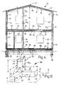
- Figs. 1 to 4 sketchily show a prefabricated house, the including its furnishings - at least kitchen and Bathroom - prefabricated as well as on-site within one day assembled for turnkey delivery becomes.
- This prefabricated house 10 is manufactured in modules, i.e. It will be complete spaces in the factory Assembled on a sort of assembly line and at the construction site only screwed.
- the floor plan 12 of the ground floor is formed by two longitudinal walls 14 and two transverse walls 16 with an exemplary length a of 1,115 cm with a width b of 750 cm.
- the upper longitudinal wall 14, which is uppermost in FIG. 1, contains a front door 15 in the center, the lower longitudinal wall 14 has on a terrace 18 a glass element 17 of length a 1 of approximately 360 cm. Such is also the - above the terrace 18 - balcony 18 a of the upper floor 20 assigned.
- the front door 15 is spanned by a balcony 18 b .
- Interior or partition walls are marked with 19 or 19 e .
- Fig. 3, 4 can be seen that on a foundation 22 with this seated concrete slab 24 multi-layer floor panels 26 of two - a cast insulation layer 27 enclosing - outer cover plates 28, 28 t and this bottom plate 26 laterally bounding wooden profiles 30 rectangular or square cross-section of the width or thickness z of 14 cm are set.
- the transverse to the image plane of Fig. 3 extending longitudinal section of the bottom plate 26 a length b 1 from here about 360 cm of Fig. 5 reveals that the upper cover plate 28 the wooden profiles 30 -or other post elements corresponding design - rests and the lower cover plate 28 t runs between the latter.
- At intervals c of about 50 cm 28 spreading profiles 29 of width c 1 of 5 cm are mounted between the cover plates.
- the expansion profiles 29 a are provided at a distance c of 60 cm between the cover plates 34, which latter include the hollow profiles 30 here on both sides.
- the lower surface of the ceiling panels 32 is provided with a cover layer 36.
- the ceiling panels 32 of the ground floor 12 are provided with insulating wool 34 bottom plates 26 a of the upper floor 20.
- the ceiling h 1 to the ceiling plate 38 of the upper floor 20 grows here - from the longitudinal walls 14 a to a transverse walls 16 a connecting ridge line 40, as shown in FIG. 4 - from about 280 cm (in Fig. 3) to 360 cm (in Fig. 4); the roof pitch w is about 15 °.
- the ceiling panels 38 which are spanned by a roof skin 41, correspond in their construction approximately to the ceiling panels 32 of the ground floor 12, as can be seen in FIG. 7, in which the length b 2 measures approximately 360 cm, the length c 60 cm and FIG Distance c 1 5 cm.
- the - equipped with windows 42 - transverse walls 14, 14 a , 16, 16 a and the intermediate walls 19, 19 a are constructed in the manner described three-layer, also spanned by a facade panel 44.
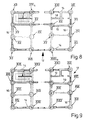
- the floor plans of Fig. 8 to 11 represent within the prefabricated house 10 the layers of connecting elements or connection nodes which latter follows below to FIG. 12 to 36 are described.
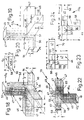
- Fig. 12 is a transport connection node or a coupling element 50 of three square tubes 46, 46 a again, which are made like commercial shaped tubes whose longitudinal axes A at angles t of 90 ° to each other and two of which - a knee forming - Tubes 46 are assigned to a horizontal surface and the third tube 46 a vertically projecting therefrom; from this, the two other tubes 46 go laterally from one of its mouths 43.
- These tubes 46, 46 a are held by - fixed to the tube walls 47 - triangular support plates 48 in addition to each other.
- the material thickness of the tube sheet is 4 mm, the free leg length f of the square tubes 46, 46 a here 300 mm and their width e 140 mm; the width e 1 of their interiors 49 thus measures 132 mm (see Fig. 13); into these interior spaces 49, the post elements or wooden profiles 30 described above are inserted with a longitudinal section 31 of length y slightly reduced in cross section as shown in FIGS. 36 to 39.
- the dimensions mentioned for material thickness, width e and side length f also apply to the connecting elements described below, which are also intended to receive those profile elements or hollow profiles 30.
- the transport connection node 50 a of FIG. 13 is provided for the ceiling portion of FIG. 9 and therefore corresponds - in the reverse position - iw the structure of Fig. 12.
- e is the outer width of the tube 46, 46 a designated which corresponds to twice the material thickness and width e 1 .
- the end edges 51 of the vertical square tube 46 a can be seen, which limit its mouth 43. Wood profiles or squared timbers 30 are inserted into the square tubes 46 a and secured with screws.
- connection node 50 wood-based panels glued and fixed with nails indissoluble.
- the coupling element 60 of FIG. 14 consists of a profile channel 62 of length f 1 of 740 mm, which is composed of a channel bottom 63 and parallel leg walls 64 of height of about 140 mm. From one of the leg walls 64 protrudes centrally a square tube 46 of the free length f of 300 mm.
- FIG. 15 shows a connection or coupling element 61 for use in the floor area.
- the ceiling area is assigned a similar coupling element 61 a , the following description also applies to the coupling element 61.
- coupling element 61 a of Fig. 16 also protrudes from a leg wall 64 and the profile bottom 63 of a profile trough 62 of length f 1 of 740 mm each centrally a square tube 46 of the leg length f of 300 mm.
- the outer width e of the square tube 46 defined by the parallel tube walls is also 140 mm here.
- the coupling element 52 of Fig. 18, 20 is corresponding to that of Fig. 12 of three square tubes 46, 46 a composed. From the one - one of the two horizontal tubes 46 remote - back surface 47 a of the vertical tube 46 a protrudes into the longitudinal axis A that distant tube 46 falling axial web 54 of length f 2 of 200 mm and the height i of 80 mm, which is formed on one of a -with the lower tube walls 47 aligned - lower edge 51 of the vertical tube 46 a outgoing fin plate 56 of width e 2 and that length f 2 .
- This is shown in FIG. 20 in each of the web 54 delimited halves with a pair of holes 58 - preferably a hole diameter of 16 mm, for example.
- Such bores 58 are otherwise present - the determination of the wood profile 30 because - in many places on the coupling elements described.
- FIG. 19 a coupling element 52 s designed mirror-inverted to FIG. 18 is presented, the fin plate 56 of which can also be seen in plan view in FIG. 20.
- coupling element 53 corresponds to iw the coupling element 52 s of FIG. 19; it is attached in Fig. 8 and Fig. 10 at the respective marked XXI point; a mirror-image designed element of this kind can be found at the points XXIs in Fig. 8 and 11 respectively.
- the coupling element 70 of Fig. 22, 23 includes three corresponding to FIG. 12 mutually associated square tubes 46, 46 a .
- From one of the square tubes 46 and its back surface 47 projects a - aligned with an adjacent to this another pipe wall 47 - side plate 66 of width e 3 of 200 mm and the free leg length f from which at the end - ie at the subsequent longitudinal edge 45 of the square tube 46 a - with a transverse wall 67 a the outer tube wall width e 1 corresponding height i 1 is connected to the one - at the adjacent edge 51 of the tube 46 a ending - step plate 68 connects; this runs parallel to the side plate 66, from which in the longitudinal center of a web strip 69 of the height i 1 rises. This forms with the parallel tube wall 47 and the intermediate portion of the side plate 66 a slide-in path 65 for a profile, not shown.
- Fig. 24 shows a further embodiment 70 a of the coupling element just described, which has a narrower step plate 68 a of width e 4 of 120 mm and holes 58 in the stepped plate 68 a and in tube walls 47.
- the coupling element 70 s of FIG corresponds in mirror image to that of FIG. 22 and is also designed according to each of the two versions of FIG. 23, 24.
- the coupling element 74 of Fig. 26, 27 has a similar to FIG. 13 basic body of two right angle forming a base tubes 46, 46 a and inclined to this angle tube 46 b of the total length n of 500 mm.
- the latter - and its longitudinal axis A - inclined at an angle w 1 of about 105 ° to the longitudinal axis A of the vertical pipe 46 a here upward and ends at an edge 51 of the square tube 46 a , which is aligned with a longitudinal edge 45 of the latter, rectangular tube 46.
- a unit of fin plate 56 and web 54 protrudes from that edge 51, the latter being directed downwards parallel to the vertical longitudinal axis A; the fin plate 56 is aligned with a tube wall 47 of the pipe 46 projecting left in FIG.
- a mirror-image 74 s of the coupling element of FIG. 26 offers FIG. 28 with an associated section through the bevel. There is also recognizable that the metal plate 76 is connected by a perpendicular thereto side wall 75 with the tube 46 b .
- a coupling element 80 with two pipe angles 82, 82 a for a roof area is shown in FIG. 29; each of these consists of two square tubes 46, 46 a .
- the one tube angle 82 is perpendicular here, the other is inclined to the upper tube wall 47 of the upper tube 46 in a - the angle w in Fig. 4 corresponding - angle w 2 of 15 ° upward upward.
- These connecting elements 80 are recognizable suitable for the corner regions of the roof slopes, wherein the lower tube angle 82 is associated with the vertical walls 14 a , 16 a and the other tube angle 82 a the roof elements.
- the stop pin or round rod 72 traverses according to FIG. 30, the interior 49 of the square tube 46 a and forms a suspension eye.
- the round rod 72 distance a 2 of the pipe edge 51 is exemplified 47.5 mm, the diameter d here 25 mm.
- the coupling element 90 of Fig. 31 consists of two at a shallow angle w 3 of about 150 ° to each other lying square tubes 86, projecting from the free ends of mutually parallel pipe stumps 88 of the free leg length f 4 of 250 mm. Not shown are holes that are provided in the pipe walls. Again, measures the width e of the tubes 86, 88 here 140 mm.
- the pipe stumps 88 protrude from the other side of the aforementioned angle w 3 limiting square tubes 86 of length n 1 from.
- This coupling element 90 a offers to the lower surface of the square tubes 86 integrally formed angle iron 92 from one to an adjacent pipe wall 47 in alignment subsequent connecting leg 93 of height h 3 of 160 mm and a rectangular cantilever 94 of the collar width k 1 of 220 mm.
- the two legs 93, 94 are secured by a central web 54 b .
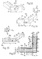
- FIG. 33 Another coupling element 96 for ceiling elements is shown in Fig. 33 with two right angles to each other directed legs 97 of the total length n 3 of 440 mm, the inner length n 4 of 300 mm and the inner wall height i 3 of 140 mm.
- Threaded plates can be seen, with which, for example, an applied wood profile 30 can be set.
- the coupling element 96 a of FIG. 34 is formed as a pipe elbow each having an outer length n 3 of 440 mm and an inner length n 4 of 300 mm with the two square tubes 46 partially removed outer walls; in each case, back surfaces 47 e , whose length n 5 corresponds to half the total length n 3 , remain.
- a square tube 97 b of the elbow is provided with an inclined outer surface 47 w ; the inner angle t 1 is here about 75 °.
- FIG. 12 The exemplary use of a connecting element 50 according to FIG. 12 reveals the configuration of an outer corner solution according to FIG. 36, also indicated in FIGS. 8, 10.
- the end sections 31 - have a length y of approximately 265 mm - the post elements or wooden profiles 30 are shortened cross-sectionally to a width z 1 .
- the outer width e of the square tubes 46, 46 a of the cross-sectional width z of the wood profiles 30 corresponds, their outer surfaces are preferably aligned with the outer surfaces of the tube walls 47; both serve to create cover plates 100 or 100 i of thickness k 2 of 19 mm and the thickness k 4 of 24 mm.
- the outer cover plate 100 is an outer plate 102 of thickness k 3 of 60 mm, the inner cover plate 100 i an inner plate 104 of thickness k 5 of only 10 mm.
- the thickness y 1 or y 2 of the longitudinal wall 14 and the transverse wall 16 each measures 255 mm.
- the connecting element 50 is installed in inner walls 19 b of thickness y 3 of 203 mm, this time as a mecaniceckling.
- the inner cover plate 100 i on the inner side of the angle also has an inner plate 104 of thickness k 5 of 10 mm.
- the other - also located in the house - plate 100 e of thickness k 6 of 19 mm, an inner plate 104 of that thickness k 5 pre-set.
- connection of a glass panel 17 a to a longitudinal wall 14 of an open Eckcontainers takes place according to FIG. 38 by means of a square full profile 106 that a intrados surface 108 abuts this longitudinal wall 14.
- the reveal surface 108 is determined by a vertical wooden section 30 and a attached thereto end plate 10 a ; the latter is adjacent to the outer as well as to the inner cover plate 100 or 100 i .
- Fig. 39 shows the connection of a bottom bar 110 for a Glass element in horizontal section; this floor latch 110 lies on the fin plate 56 of the coupling element 52 and its vertical web 54 laterally.
- FIG. 41 shows the enlarged section according to box XLI of the vertical section of FIG. 3 with the adjacent corner areas of the ceiling of a container or a room cell on the ground floor 12 and on the upper floor 20. Visible here is an air gap 114 a between the ceiling panel 32 the lower container and the lower cover plate 28 t of the upper bottom plate 26 a and on the other hand, the floor covering 37 on the upper cover plate 28; the latter is secured all around by bottom strips 37 a .
- the adjacent longitudinal edges of the two aligned facade panel 44 are connected by a horizontal profile insert 116.
- FIG. 3 The corresponding vertical section through the base area according to field XLII of FIG. 3 is shown in FIG.
- the foundation 22 and the concrete slab 24 the bottom plate 26 to form a horizontal air gap 114 above an intermediate plate 118.
- the square profile 30 k serves as a support for the lower cover plate 28 t of the bottom plate 26.
- Air gaps 114 extend between - for example, at a distance of 60 cm parallel adjacent - post elements or wooden profiles 30 of the bottom plate 26th
- connection area container wall element is shown in the horizontal section of FIG. 43.
- the facade panel 44 of the left in Figure 43 element is overlapped by the free end of an outer plate 120 which rests on an end face of a square plate 13 b ; the latter projects beyond the facade panel 44 and allows the introduction of insulating wool 35 a behind that outer panel 120th
- the coupling elements described are usually per building used four times, only the coupling elements for the roof area only twice.
Landscapes
- Engineering & Computer Science (AREA)
- Architecture (AREA)
- Physics & Mathematics (AREA)
- Electromagnetism (AREA)
- Civil Engineering (AREA)
- Structural Engineering (AREA)
- Joining Of Building Structures In Genera (AREA)
- Load-Bearing And Curtain Walls (AREA)
- Coating By Spraying Or Casting (AREA)
- Buildings Adapted To Withstand Abnormal External Influences (AREA)
Abstract
Description
- Fig. 1, 2:
- jeweils den Grundriss eines Fertighauses für dessen Erdgeschoss bzw. dessen Obergeschoss;
- Fig. 3, 4:
- einen gegenüber Fig. 1, 2 vergrößerten Längsschnitt durch das Fertighaus nach Linie III-III bzw. einen Querschnitt nach Linie IV-IV der Fig. 1, 2;
- Fig. 5:
- einen quer zu dem in Fig. 3 mit V bezeichneten Bodenelement des Erdgeschosses verlaufenden Längsschnitt durch dieses;
- Fig. 6:
- einen Längsschnitt durch ein Bodenelement im Obergeschoss quer zu dem in Fig. 3 mit VI kenntlich gemachten Element;
- Fig. 7:
- einen Schnitt durch ein Dachelement VII der Fig. 3;
- Fig. 8:
- den Grundriss des Erdgeschosses mit in diesem bodennah angebrachten Verbindungselementen, wobei in den Fig. 8 bis 11 mit römischen Zahlen die Bezifferungen der die Verbindungselemente wiedergebenden Figuren der Zeichnung kenntlich gemacht sind;
- Fig. 9:
- den Grundriss des Erdgeschosses mit in seinem oberen Bereich vorgesehenen Verbindungselementen;
- Fig. 10:
- den Grundriss des Obergeschosses mit dessen Bodenbereich zugeordneten Verbindungselementen;
- Fig. 11:
- den Grundriss des Obergeschosses mit Verbindungselementen in dessen Deckenbereich;;
- Fig. 12:
- eine Schrägsicht auf einen Eckverbinder als Transportverbindungsknoten mit drei zueinander rechtwinkelig verlaufenden Hohlprofilen, die -- wie oben erwähnt -- in Fig. 8, 10 bei XII angeordnet sind;
- Fig. 13:
- einen Eckverbinder in Schrägsicht mit drei Hohlprofilen für den Deckenbereich (in Fig. 9 bei XIII);
- Fig. 14:
- einen Eckverbinder aus einem Rinnenprofil mit Hohlprofilansatz in Schrägsicht (in Fig. 8, 9, 11 bei XIV) ;
- Fig. 15:
- einen Eckverbinder für den Bodenbereich in Schrägsicht mit einem Rinnenprofil und zwei zu diesem rechtwinkeligen Hohlprofilen (in Fig. 8, 10 bei XV);
- Fig. 16, 17:
- eine Schrägsicht auf einen Eckverbinder für den Deckenbereich aus einem Rinnenprofil und zwei Rohrteilen (in Fig. 9, 11 bei XVI) bzw. die Draufsicht auf diesen;
- Fig. 18:
- einen anderen Eckverbinder oder Transportverbindungsknoten in Schrägsicht mit drei zueinander ebenfalls rechtwinkelig verlaufenden rohrartigen Bestandteilen sowie mit einem Kragelement (in Fig. 8, 10 bei XVIII) ;
- Fig. 19:
- eine zu Fig. 18 spiegelbildliche Ausführung des Eckverbinders (in Fig. 8, 10 bei XIX);
- Fig. 20:
- die Draufsicht auf das Kragelement der Fig. 18, 19;
- Fig. 21:
- einen der Fig. 19 etwa entsprechenden Eckverbinder in Schrägsicht mit anders gestaltetem Kragelement (in Fig. 8, 10 bei XXI);
- Fig. 22:
- eine Schrägsicht auf einen anderen Eckverbinder mit einem Rohrknie sowie zusätzlichen Seitenprofilen (in Fig. 9 bei XXII bzw. XXIIa);
- Fig. 23, 24:
- jeweils eine Draufsicht auf zwei unterschiedlichen Detailgestaltungen zu Fig. 22 (in Fig. 9 als XXII bzw. XXIIa);
- Fig. 25:
- einen zu Fig. 22 spiegelbildlichen Eckverbinder in Schrägsicht (in Fig. 9 bei XXV);
- Fig. 26:
- einen der Fig. 21 ähnlichen Eckverbinder mit zusätzlichen Seitenanbauten in Schrägsicht (in Fig. 11 bei XXVI);
- Fig. 27:
- die beiden Seitenansichten zu Fig. 26;
- Fig. 28:
- einen zu Fig. 26 i.w. spiegelbildlichen Eckverbinder in Schrägsicht (in Fig. 11 bei XXVIII) mit zugeordnetem Querschnitt;
- Fig. 29:
- eine Schrägsicht auf einen Eckverbinder mit vier Rohrprofilen (in Fig. 11 bei XXIX sowie spiegelbildlich bei XXIXs) mit zugeordneter Seitenansicht;
- Fig. 30:
- eine schräge Draufsicht auf eine Einhängeöse als Detail der Fig. 23, 26, 28;
- Fig. 31:
- ein mehrfach gekantetes Hohlprofil rechteckigen Querschnitts in Schrägsicht (in Fig. 11 bei XXXI);
- Fig. 32:
- ein weiteres mehrfach gekantetes Hohlprofil rechteckigen Querschnitts in Schrägsicht mit Anbauteilen (in Fig. 11 bei XXXII);
- Fig. 33:
- ein winkelartiges Kupplungselement für Deckenelemente in Schrägsicht;
- Fig. 34, 35:
- jeweils eine Schrägsicht auf ein der Darstellung in Fig. 33 ähnliches Kupplungselement mit zugeordnetem Querschnitt;
- Fig. 36:
- einen Horizontalschnitt durch ein Außeneck eines Eckcontainers als Hausteil;
- Fig. 37:
- einen Horizontalschnitt durch ein Inneneck eines Eckcontainers;
- Fig. 38:
- einen Schnitt durch einen Anschluss eines Glaselementes mit offenem Eckcontainer;
- Fig. 39:
- einen Horizontalschnitt durch einen Anschluss eines Bodenriegels für das Glaselement;
- Fig. 40:
- einen Vertikalschnitt durch einen Abschnitt einer Zwischenwand;
- Fig. 41:
- einen Vertikalschnitt durch einen Anschluss zweier Container oder Raumzellen für Erd- bzw. Obergeschoss eines Hauses als vergrößerter Ausschnitt aus Fig. 3 nach deren Feld XLI;
- Fig. 42:
- einen gegenüber Fig. 3 vergrößerten Vertikalschnitt durch deren Sockelbereich gemäß ihrem Feld XLII;
- Fig. 43:
- einen Horizontalschnitt durch einen Anschlussbereich Container-Wandelement;
- Fig. 44:
- eine Grundrissskizze mit der Lage eines Kaminschachtes an einer Innenwand;
- Fig. 45:
- den gegenüber einem Feld XLV der Fig. 44 vergrößerten Horizontalschnitt durch einen Wandanschluss mit dem Kaminschacht.
Claims (24)
- Vorrichtung in Form eines Bauwerkes mit wenigstens einem Raum, der einen von Wandelementen umgebenen sowie von einem Deckenelement überspannten Bodenbereich aufweist, wobei die flächig ausgebildeten Wand-, Bodenund Deckenelemente außerhalb des Standortes vorgefertigt sind,
dadurch gekennzeichnet, dass zumindest zwei in einem Winkel (t, w) zueinander angeordnete flächige Elemente (12, 16, 19; 26, 32, 38) durch Knoten- oder Verbindungselemente (50, 50a, 52, 52s; 53, 60; 61; 61a; 70, 70a, 70s; 74, 74s; 80, 90, 90a; 96, 96a, 96b) miteinander transportfähig verbunden sind, wobei die metallischen Verbindungselemente rohrförmige Abschnitte (46, 46a, 46b; 86, 88, 97) zur Aufnahme jeweils eines Pfostenelements (30) entsprechenden Querschnitts aufweisen sowie die flächigen Elemente die Umrisse einer transportablen Raumzelle bzw. eines Containers bestimmen, die/der mit Installationen versehen ist. - Vorrichtung nach Anspruch 1, dadurch gekennzeichnet, dass die rohrförmigen Abschnitte (46, 46a, 46b; 86, 88, 97) einen rechteckigen Querschnitt aufweisen, insbesondere einen quadratischen Querschnitt.
- Vorrichtung nach Anspruch 1 oder 2, dadurch gekennzeichnet, dass die äußere Breite (e) des rohrförmigen Abschnitts (46, 46a, 46b; 86, 88, 97) aus Rohrblech der Dicke (z) des Holzprofils oder Pfostenelements (30) entspricht und dieses mit einem Endabschnitt (31) in den rohrförmigen Abschnitt eingesetzt ist, wobei die Weite (e1) von dessen Innenraum (49) der Breite (z1) des Endabschnitts entspricht.
- Vorrichtung nach einem der Ansprüche 1 bis 3, dadurch gekennzeichnet, dass das Verbindungselement (50, 50a; 52, 53; 70, 70s) drei rohrförmige Abschnitte (46, 46a) enthält, deren Längsachsen (A) im rechten Winkel (t) zueinander verlaufen, wobei gegebenenfalls zwei rohrförmige Abschnitte (46) von jeweils einer Rohrwand (47a) des dritten rohrförmigen Abschnitts (46a) an dessen Rohrmündung (43) ausgehen.
- Vorrichtung nach Anspruch 4, dadurch gekennzeichnet, dass an einer dritten Rohrwand (47a) des dritten rohrförmigen Abschnitts (46a) von einer die benachbarte Rohrmündung (43) begrenzenden Kante des Verbindungselementes (52, 53) ein Flossenblech (56) ausgeht.
- Vorrichtung nach Anspruch 5, dadurch gekennzeichnet, dass das mit der Ebene der Rohrmündung (43) fluchtende Flossenblech (56) rechteckigen Grundrisses durch einen kammartigen mittigen Steg (54) gleicher Kraglänge (f2) mit der Rohrwandung (47a) oder durch einen etwa dreiecksförmigen mittigen Steg (54a) mit der Rohrwand (47a) zusätzlich verbunden ist, wobei dessen Kraglänge (f3) kürzer ist als die Kraglänge (f2) des Flossenbleches (Fig. 21).
- Vorrichtung nach Anspruch 6, dadurch gekennzeichnet, dass die Höhe (i) des Steges (54, 54a) kürzer ist als die Kraglänge (f2) des Flossenbleches (56), das bevorzugt beidseits des Steges mit Bohrungen (58) versehen ist.
- Vorrichtung nach einem der Ansprüche 1 bis 4, dadurch gekennzeichnet, dass an einem der rohrförmigen Abschnitte (46) des Verbindungselementes (70, 70s) ein mit einer Rohrwand (47) fluchtendes, der freien Schenkellänge (f) des rohrförmigen Abschnitts etwa entsprechendes Seitenblech (66) festgelegt ist, das entlang einer Längskante (45) des rohrförmigen Abschnitts verläuft und entlang der Längskante des rechtwinkelig angebrachten anderen rohrförmigen Abschnitts (46a) in eine Querwand (67) übergeht, an welche ein zum Seitenblech paralleles Stufenblech (68) angeformt ist (Fig. 22, 25).
- Vorrichtung nach Anspruch 8, gekennzeichnet durch einen etwa in Längsmitte des Seitenblechs (66) verlaufenden und mit diesem verbundenen Stegstreifen (69) gleicher Schenkellänge (f), wobei gegebenenfalls der Stegstreifen mit einem Teil des Seitenblechs sowie der anschließenden Rohrwand (47) eine Einschubbahn (65) begrenzt.
- Vorrichtung nach einem der Ansprüche 1 bis 4, dadurch gekennzeichnet, dass das Verbindungselement (74, 74s) einen rechten Winkel aus zwei aneinandergefügten rohrförmigen Abschnitten (46, 46a) aufweist, an den ein in einem Winkel (w1) von mehr als 90° zu einer Längsachse (A) sowie zu einer Rohrwand (47a) von letzterer ein dritter rohrförmiger Abschnitt (46b) abragt (Fig. 27, 28).
- Vorrichtung nach Anspruch 10, dadurch gekennzeichnet, dass von einer Seitenwand des geneigten rohrförmigen Abschnittes (46b) parallel zu dessen Längsachse (A1) eine Blechplatte (76) abragt mit einer quer zu ihr verlaufenden Endplatte (77), wobei gegebenenfalls in Längsmitte der Blechplatte von dieser ein Steg (78) aufragt, der einends an die Endplatte angeschlossen ist.
- Vorrichtung nach Anspruch 11, dadurch gekennzeichnet, dass der geneigte rohrförmige Abschnitt (46b) mit einem Abschnitt der Blechplatte (76) und dem Steg (78) eine Einschubbahn begrenzt.
- Vorrichtung nach einem der Ansprüche 10 bis 12, dadurch gekennzeichnet, dass von einem der rechtwinkelig aneinandergefügten rohrförmigen Abschnitte (46a) ein Flossenblech (56) mit mittigem kammartigen Steg (54) abragt, wobei letzterer parallel zur Rohrlängsachse (A) verläuft und gegebenenfalls das Flossenblech samt Steg der Endplatte (77) der Blechplatte (76) benachbart ist.
- Vorrichtung nach einem der Ansprüche 1 bis 13, dadurch gekennzeichnet, dass zumindest einer der rohrförmigen Abschnitte (46a) im Bereich seiner den anderen rohrförmigen Abschnitten (46) zugeordneten Mündungskanten (51) mit zumindest einem seinen Innenraum (49) querenden Anschlagstift oder Rundstab (72) versehen ist.
- Vorrichtung nach einem der Ansprüche 1 bis 3, dadurch gekennzeichnet, dass von einer Schenkelwand (64) einer Profilrinne (62) des Verbindungselementes (60, 61, 61a) ein rohrförmiger Abschnitt (46) abragt, bevorzugt in Längsmitte der Schenkelwand, wobei gegebenenfalls dem rohrförmigen Abschnitt der Schenkelwand der Profilrinne an deren Profilboden (63) ein anderer rohrförmiger Abschnitt des Verbindungselementes (61, 61a) zugeordnet ist (Fig. 15, 16).
- Vorrichtung nach einem der Ansprüche 1 bis 3, dadurch gekennzeichnet, dass das Verbindungselement (80) zwei Rohrwinkel (82, 82a) aus jeweils zwei rohrförmigen Abschnitten (46, 46a) aufweist, sowie der eine rohrförmige Abschnitt (46) des einen Rohrwinkels (82) einem rohrförmigen Abschnitt (46) des anderen Rohrwinkels (82a) in einem Neigungswinkel (w2) zugeordnet ist und dessen anderer Abschnitt (46a) von der Ebene der anderen drei Abschnitte etwa rechtwinkelig abragt, wobei gegebenenfalls der Neigungswinkel (w2) etwa 10° bis 20°, bevorzugt etwa 15° misst.
- Vorrichtung nach einem der Ansprüche 1 bis 16, gekennzeichnet durch eine freie Schenkellänge (f) der rohrförmigen Abschnitte (46, 46a, 46b; 86,88, 97) von etwa 300 mm.
- Vorrichtung nach einem der Ansprüche 1 bis 3, dadurch gekennzeichnet, dass von zwei in einem Winkel (w3) von mehr als 90° ihrer Längsachsen (A) aneinandergrenzenden rohrförmigen Abschnitten (86) am freien Ende jeweils ein Rohrstumpf (88) abragt und beide Rohrstümpfe des Verbindungselementes (90, 90a) zueinander parallel gerichtet sind (Fig. 31, 32).
- Vorrichtung nach Anspruch 18, dadurch gekennzeichnet, dass von der Rückenfläche (47) der beiden rohrförmigen Abschnitte (86) des Verbindungselementes (90a) jeweils ein Winkeleisen (92) abragt, dessen einer Schenkel (93) mit der Rückenfläche fluchtet, wobei beide Winkeleisen im Anstoßbereich miteinander verbunden sind, welch letztere gegebenenfalls einen in der Mitte des Winkels (w3) eine Symmetrieebene bildenden Steg (54b) enthält.
- Vorrichtung nach einem der Ansprüche 1 bis 19, dadurch gekennzeichnet, dass zumindest zwei der mit einem Verbindungselement ((50, 50a, 52, 52s; 53, 60; 61; 61a; 70, 70a, 70s; 74, 74s; 80, 90, 90a; 96, 96a, 96b) versehenen Pfostenelemente (30) mit an sie in Abstand (e) parallel zueinander angeschlagenen Platten (28, 28t; 100, 100e, 100i) sowie zumindest zwischen diesen angeordneten Dämmschichten (27, 35) ein flächiges Element (12, 16, 19; 26, 32, 38) bestimmen.
- Vorrichtung nach wenigstens einem der Ansprüche 1 bis 20, gekennzeichnet durch ein weiteres der in Beschreibung und/oder Zeichnung enthaltenen Merkmale.
- Verfahren zum Errichten eines Bauwerkes mit wenigstens einem Raum, der einen von Wandelementen umgebenen sowie von Deckenelementen überspannten Bodenbereich aufweist, nach zumindest einem der voraufgehenden Ansprüche, dadurch gekennzeichnet, dass eine/ein derartige/r Raumzelle oder Container vorgefertigt, mit Installationen versehen sowie dem Einbauort zugeführt wird, wobei zumindest zwei der Raumzellen bzw. Container miteinander an dem/den Verbindungselement/en ((50, 50a, 52, 52s; 53, 60; 61; 61a; 70, 70a, 70s; 74, 74s; 80, 90, 90a; 96, 96a, 96b) verbunden sowie die einends in der Raumzelle bzw. deren Container am Einbauort festliegenden Profilelemente (30) andernends in ein Verbindungselement der benachbarten Raumzelle/n eingefügt werden.
- Verfahren nach Anspruch 22, dadurch gekennzeichnet, dass die Raumzellen bzw. Container miteinander verschraubt werden.
- Verfahren nach Anspruch 22 oder 23, gekennzeichnet durch wenigstens ein weiteres der in Beschreibung und/oder Zeichnung offenbarten Merkmale.
Applications Claiming Priority (2)
| Application Number | Priority Date | Filing Date | Title |
|---|---|---|---|
| DE10349897 | 2003-10-14 | ||
| DE10349897 | 2003-10-14 |
Publications (2)
| Publication Number | Publication Date |
|---|---|
| EP1524374A1 true EP1524374A1 (de) | 2005-04-20 |
| EP1524374B1 EP1524374B1 (de) | 2010-06-09 |
Family
ID=34353491
Family Applications (1)
| Application Number | Title | Priority Date | Filing Date |
|---|---|---|---|
| EP04024392A Expired - Lifetime EP1524374B1 (de) | 2003-10-14 | 2004-10-13 | Vorrichtung in Form eines Bauwerks sowie Verfahren zum Errichten eines solchen Bauwerks |
Country Status (3)
| Country | Link |
|---|---|
| EP (1) | EP1524374B1 (de) |
| AT (1) | ATE470766T1 (de) |
| DE (2) | DE502004011257D1 (de) |
Citations (3)
| Publication number | Priority date | Publication date | Assignee | Title |
|---|---|---|---|---|
| US3836270A (en) * | 1972-12-18 | 1974-09-17 | J Chambers | Framework connector |
| GB2140525A (en) * | 1983-05-20 | 1984-11-28 | Allan Jones | Construction apparatus and method |
| DE4027137A1 (de) * | 1990-08-28 | 1992-03-05 | Kurt Dipl Ing Karl | Containereinheit |
-
2004
- 2004-10-13 EP EP04024392A patent/EP1524374B1/de not_active Expired - Lifetime
- 2004-10-13 DE DE502004011257T patent/DE502004011257D1/de not_active Expired - Lifetime
- 2004-10-13 AT AT04024392T patent/ATE470766T1/de active
- 2004-10-13 DE DE102004049937A patent/DE102004049937A1/de not_active Withdrawn
Patent Citations (3)
| Publication number | Priority date | Publication date | Assignee | Title |
|---|---|---|---|---|
| US3836270A (en) * | 1972-12-18 | 1974-09-17 | J Chambers | Framework connector |
| GB2140525A (en) * | 1983-05-20 | 1984-11-28 | Allan Jones | Construction apparatus and method |
| DE4027137A1 (de) * | 1990-08-28 | 1992-03-05 | Kurt Dipl Ing Karl | Containereinheit |
Also Published As
| Publication number | Publication date |
|---|---|
| EP1524374B1 (de) | 2010-06-09 |
| DE102004049937A1 (de) | 2005-05-25 |
| DE502004011257D1 (de) | 2010-07-22 |
| ATE470766T1 (de) | 2010-06-15 |
Similar Documents
| Publication | Publication Date | Title |
|---|---|---|
| DE69430122T2 (de) | Systeme für vorgefertigte gebäude | |
| DE3430612A1 (de) | Metall-raumfachwerk aus einzelelementen zum errichten von gebaeuden | |
| EP0639677B1 (de) | Gebäude, bestehend aus Modulen vorgefertigter Bauzellen | |
| EP3051039A1 (de) | Gebäudesystem, insbesondere für Wohn- und Arbeitszwecke | |
| EP2722451B1 (de) | Gebäudesystem, insbesondere Wohngebäude | |
| DE69903131T2 (de) | Modulares bauelement | |
| EP1859108B1 (de) | Rahmen für gebäude | |
| DE7102932U (de) | Faltbares gebaeude | |
| DE3532846C2 (de) | Bauelement zur Erstellung von Gebäuden, auch zur Erstellung von Gebäudemodellen | |
| DE10348455B4 (de) | Vorrichtung in Form eines Bauwerks sowie Verfahren zum Errichten eines solchen Bauwerks | |
| EP1524374B1 (de) | Vorrichtung in Form eines Bauwerks sowie Verfahren zum Errichten eines solchen Bauwerks | |
| DE29618522U1 (de) | Bausatz für ein Fertigteilhaus | |
| DE4003961A1 (de) | Raumzelle, insbesondere wohncontainer | |
| DE3306456A1 (de) | Bauelement | |
| DE4211435A1 (de) | Integrationsbauverfahren und Baustein für seine Durchführung | |
| EP0717158B1 (de) | Raumbausteinsystem für das Erstellen von Bauwerken | |
| DE4314714A1 (de) | Raumkörper zur Errichtung von Bauwerken und Verfahren zu seiner Herstellung | |
| DE1609522B2 (de) | Wohneinheit aus metallischen Fertigteilen | |
| DE4229719A1 (de) | Bauelementensatz für ein Gebäude | |
| DE2900477A1 (de) | Gebaeude, insbesondere fertighaus | |
| DE3808259A1 (de) | Aus vorgefertigten stahlbeton-teilen zusammensetzbares gebaeude | |
| DE2852044A1 (de) | Wandelement | |
| DE2309455A1 (de) | Raumkaesten fuer fertighaeuser | |
| DE811399C (de) | Bauweise im Holzbau | |
| DE4423423A1 (de) | Verfahren zur Herstellung einer Wohneinheit - Fertighaus - sowie Bodenrahmen dazu |
Legal Events
| Date | Code | Title | Description |
|---|---|---|---|
| PUAI | Public reference made under article 153(3) epc to a published international application that has entered the european phase |
Free format text: ORIGINAL CODE: 0009012 |
|
| AK | Designated contracting states |
Kind code of ref document: A1 Designated state(s): AT BE BG CH CY CZ DE DK EE ES FI FR GB GR HU IE IT LI LU MC NL PL PT RO SE SI SK TR |
|
| AX | Request for extension of the european patent |
Extension state: AL HR LT LV MK |
|
| 17P | Request for examination filed |
Effective date: 20051013 |
|
| AKX | Designation fees paid |
Designated state(s): AT BE BG CH CY CZ DE DK EE ES FI FR GB GR HU IE IT LI LU MC NL PL PT RO SE SI SK TR |
|
| 17Q | First examination report despatched |
Effective date: 20071217 |
|
| GRAP | Despatch of communication of intention to grant a patent |
Free format text: ORIGINAL CODE: EPIDOSNIGR1 |
|
| GRAS | Grant fee paid |
Free format text: ORIGINAL CODE: EPIDOSNIGR3 |
|
| GRAA | (expected) grant |
Free format text: ORIGINAL CODE: 0009210 |
|
| AK | Designated contracting states |
Kind code of ref document: B1 Designated state(s): AT BE BG CH CY CZ DE DK EE ES FI FR GB GR HU IE IT LI LU MC NL PL PT RO SE SI SK TR |
|
| REG | Reference to a national code |
Ref country code: CH Ref legal event code: EP |
|
| REG | Reference to a national code |
Ref country code: IE Ref legal event code: FG4D Free format text: LANGUAGE OF EP DOCUMENT: GERMAN |
|
| REF | Corresponds to: |
Ref document number: 502004011257 Country of ref document: DE Date of ref document: 20100722 Kind code of ref document: P |
|
| REG | Reference to a national code |
Ref country code: NL Ref legal event code: VDEP Effective date: 20100609 |
|
| PG25 | Lapsed in a contracting state [announced via postgrant information from national office to epo] |
Ref country code: SE Free format text: LAPSE BECAUSE OF FAILURE TO SUBMIT A TRANSLATION OF THE DESCRIPTION OR TO PAY THE FEE WITHIN THE PRESCRIBED TIME-LIMIT Effective date: 20100609 |
|
| PG25 | Lapsed in a contracting state [announced via postgrant information from national office to epo] |
Ref country code: FI Free format text: LAPSE BECAUSE OF FAILURE TO SUBMIT A TRANSLATION OF THE DESCRIPTION OR TO PAY THE FEE WITHIN THE PRESCRIBED TIME-LIMIT Effective date: 20100609 Ref country code: SI Free format text: LAPSE BECAUSE OF FAILURE TO SUBMIT A TRANSLATION OF THE DESCRIPTION OR TO PAY THE FEE WITHIN THE PRESCRIBED TIME-LIMIT Effective date: 20100609 |
|
| PG25 | Lapsed in a contracting state [announced via postgrant information from national office to epo] |
Ref country code: CY Free format text: LAPSE BECAUSE OF FAILURE TO SUBMIT A TRANSLATION OF THE DESCRIPTION OR TO PAY THE FEE WITHIN THE PRESCRIBED TIME-LIMIT Effective date: 20100609 Ref country code: GR Free format text: LAPSE BECAUSE OF FAILURE TO SUBMIT A TRANSLATION OF THE DESCRIPTION OR TO PAY THE FEE WITHIN THE PRESCRIBED TIME-LIMIT Effective date: 20100910 Ref country code: PL Free format text: LAPSE BECAUSE OF FAILURE TO SUBMIT A TRANSLATION OF THE DESCRIPTION OR TO PAY THE FEE WITHIN THE PRESCRIBED TIME-LIMIT Effective date: 20100609 |
|
| REG | Reference to a national code |
Ref country code: IE Ref legal event code: FD4D |
|
| PG25 | Lapsed in a contracting state [announced via postgrant information from national office to epo] |
Ref country code: NL Free format text: LAPSE BECAUSE OF FAILURE TO SUBMIT A TRANSLATION OF THE DESCRIPTION OR TO PAY THE FEE WITHIN THE PRESCRIBED TIME-LIMIT Effective date: 20100609 Ref country code: EE Free format text: LAPSE BECAUSE OF FAILURE TO SUBMIT A TRANSLATION OF THE DESCRIPTION OR TO PAY THE FEE WITHIN THE PRESCRIBED TIME-LIMIT Effective date: 20100609 Ref country code: IE Free format text: LAPSE BECAUSE OF FAILURE TO SUBMIT A TRANSLATION OF THE DESCRIPTION OR TO PAY THE FEE WITHIN THE PRESCRIBED TIME-LIMIT Effective date: 20100609 |
|
| PG25 | Lapsed in a contracting state [announced via postgrant information from national office to epo] |
Ref country code: PT Free format text: LAPSE BECAUSE OF FAILURE TO SUBMIT A TRANSLATION OF THE DESCRIPTION OR TO PAY THE FEE WITHIN THE PRESCRIBED TIME-LIMIT Effective date: 20101011 Ref country code: CZ Free format text: LAPSE BECAUSE OF FAILURE TO SUBMIT A TRANSLATION OF THE DESCRIPTION OR TO PAY THE FEE WITHIN THE PRESCRIBED TIME-LIMIT Effective date: 20100609 Ref country code: RO Free format text: LAPSE BECAUSE OF FAILURE TO SUBMIT A TRANSLATION OF THE DESCRIPTION OR TO PAY THE FEE WITHIN THE PRESCRIBED TIME-LIMIT Effective date: 20100609 Ref country code: SK Free format text: LAPSE BECAUSE OF FAILURE TO SUBMIT A TRANSLATION OF THE DESCRIPTION OR TO PAY THE FEE WITHIN THE PRESCRIBED TIME-LIMIT Effective date: 20100609 |
|
| PG25 | Lapsed in a contracting state [announced via postgrant information from national office to epo] |
Ref country code: IT Free format text: LAPSE BECAUSE OF FAILURE TO SUBMIT A TRANSLATION OF THE DESCRIPTION OR TO PAY THE FEE WITHIN THE PRESCRIBED TIME-LIMIT Effective date: 20100609 |
|
| PLBE | No opposition filed within time limit |
Free format text: ORIGINAL CODE: 0009261 |
|
| STAA | Information on the status of an ep patent application or granted ep patent |
Free format text: STATUS: NO OPPOSITION FILED WITHIN TIME LIMIT |
|
| PG25 | Lapsed in a contracting state [announced via postgrant information from national office to epo] |
Ref country code: DK Free format text: LAPSE BECAUSE OF FAILURE TO SUBMIT A TRANSLATION OF THE DESCRIPTION OR TO PAY THE FEE WITHIN THE PRESCRIBED TIME-LIMIT Effective date: 20100609 |
|
| BERE | Be: lapsed |
Owner name: PRESCHAN, WOLFGANG Effective date: 20101031 |
|
| 26N | No opposition filed |
Effective date: 20110310 |
|
| PG25 | Lapsed in a contracting state [announced via postgrant information from national office to epo] |
Ref country code: MC Free format text: LAPSE BECAUSE OF NON-PAYMENT OF DUE FEES Effective date: 20101031 |
|
| REG | Reference to a national code |
Ref country code: CH Ref legal event code: PL |
|
| GBPC | Gb: european patent ceased through non-payment of renewal fee |
Effective date: 20101013 |
|
| REG | Reference to a national code |
Ref country code: DE Ref legal event code: R097 Ref document number: 502004011257 Country of ref document: DE Effective date: 20110309 |
|
| PG25 | Lapsed in a contracting state [announced via postgrant information from national office to epo] |
Ref country code: FR Free format text: LAPSE BECAUSE OF NON-PAYMENT OF DUE FEES Effective date: 20101102 Ref country code: CH Free format text: LAPSE BECAUSE OF NON-PAYMENT OF DUE FEES Effective date: 20101031 Ref country code: LI Free format text: LAPSE BECAUSE OF NON-PAYMENT OF DUE FEES Effective date: 20101031 |
|
| REG | Reference to a national code |
Ref country code: FR Ref legal event code: ST Effective date: 20110630 |
|
| PG25 | Lapsed in a contracting state [announced via postgrant information from national office to epo] |
Ref country code: BE Free format text: LAPSE BECAUSE OF NON-PAYMENT OF DUE FEES Effective date: 20101031 Ref country code: GB Free format text: LAPSE BECAUSE OF NON-PAYMENT OF DUE FEES Effective date: 20101013 |
|
| REG | Reference to a national code |
Ref country code: DE Ref legal event code: R119 Ref document number: 502004011257 Country of ref document: DE Effective date: 20110502 |
|
| PG25 | Lapsed in a contracting state [announced via postgrant information from national office to epo] |
Ref country code: HU Free format text: LAPSE BECAUSE OF FAILURE TO SUBMIT A TRANSLATION OF THE DESCRIPTION OR TO PAY THE FEE WITHIN THE PRESCRIBED TIME-LIMIT Effective date: 20101210 Ref country code: LU Free format text: LAPSE BECAUSE OF NON-PAYMENT OF DUE FEES Effective date: 20101013 Ref country code: BG Free format text: LAPSE BECAUSE OF FAILURE TO SUBMIT A TRANSLATION OF THE DESCRIPTION OR TO PAY THE FEE WITHIN THE PRESCRIBED TIME-LIMIT Effective date: 20100609 |
|
| PG25 | Lapsed in a contracting state [announced via postgrant information from national office to epo] |
Ref country code: TR Free format text: LAPSE BECAUSE OF FAILURE TO SUBMIT A TRANSLATION OF THE DESCRIPTION OR TO PAY THE FEE WITHIN THE PRESCRIBED TIME-LIMIT Effective date: 20100609 |
|
| PGFP | Annual fee paid to national office [announced via postgrant information from national office to epo] |
Ref country code: AT Payment date: 20121022 Year of fee payment: 9 |
|
| PG25 | Lapsed in a contracting state [announced via postgrant information from national office to epo] |
Ref country code: DE Free format text: LAPSE BECAUSE OF NON-PAYMENT OF DUE FEES Effective date: 20110502 |
|
| PG25 | Lapsed in a contracting state [announced via postgrant information from national office to epo] |
Ref country code: BG Free format text: LAPSE BECAUSE OF FAILURE TO SUBMIT A TRANSLATION OF THE DESCRIPTION OR TO PAY THE FEE WITHIN THE PRESCRIBED TIME-LIMIT Effective date: 20100909 |
|
| PG25 | Lapsed in a contracting state [announced via postgrant information from national office to epo] |
Ref country code: ES Free format text: LAPSE BECAUSE OF FAILURE TO SUBMIT A TRANSLATION OF THE DESCRIPTION OR TO PAY THE FEE WITHIN THE PRESCRIBED TIME-LIMIT Effective date: 20100920 |
|
| REG | Reference to a national code |
Ref country code: AT Ref legal event code: MM01 Ref document number: 470766 Country of ref document: AT Kind code of ref document: T Effective date: 20131013 |
|
| PG25 | Lapsed in a contracting state [announced via postgrant information from national office to epo] |
Ref country code: AT Free format text: LAPSE BECAUSE OF NON-PAYMENT OF DUE FEES Effective date: 20131013 |