EP1524348B1 - Vorrichtung zur Platinenauswahl in einer Rundstrickmaschine zum Stricken von Strumpfwaren oder dergleichen - Google Patents
Vorrichtung zur Platinenauswahl in einer Rundstrickmaschine zum Stricken von Strumpfwaren oder dergleichen Download PDFInfo
- Publication number
- EP1524348B1 EP1524348B1 EP04021033A EP04021033A EP1524348B1 EP 1524348 B1 EP1524348 B1 EP 1524348B1 EP 04021033 A EP04021033 A EP 04021033A EP 04021033 A EP04021033 A EP 04021033A EP 1524348 B1 EP1524348 B1 EP 1524348B1
- Authority
- EP
- European Patent Office
- Prior art keywords
- sinker
- selector
- pusher
- ring
- selection
- Prior art date
- Legal status (The legal status is an assumption and is not a legal conclusion. Google has not performed a legal analysis and makes no representation as to the accuracy of the status listed.)
- Expired - Lifetime
Links
Images

Classifications
-
- D—TEXTILES; PAPER
- D04—BRAIDING; LACE-MAKING; KNITTING; TRIMMINGS; NON-WOVEN FABRICS
- D04B—KNITTING
- D04B15/00—Details of, or auxiliary devices incorporated in, weft knitting machines, restricted to machines of this kind
- D04B15/06—Sinkers
-
- D—TEXTILES; PAPER
- D04—BRAIDING; LACE-MAKING; KNITTING; TRIMMINGS; NON-WOVEN FABRICS
- D04B—KNITTING
- D04B15/00—Details of, or auxiliary devices incorporated in, weft knitting machines, restricted to machines of this kind
- D04B15/14—Needle cylinders
-
- D—TEXTILES; PAPER
- D04—BRAIDING; LACE-MAKING; KNITTING; TRIMMINGS; NON-WOVEN FABRICS
- D04B—KNITTING
- D04B15/00—Details of, or auxiliary devices incorporated in, weft knitting machines, restricted to machines of this kind
- D04B15/32—Cam systems or assemblies for operating knitting instruments
- D04B15/34—Cam systems or assemblies for operating knitting instruments for dials
-
- D—TEXTILES; PAPER
- D04—BRAIDING; LACE-MAKING; KNITTING; TRIMMINGS; NON-WOVEN FABRICS
- D04B—KNITTING
- D04B15/00—Details of, or auxiliary devices incorporated in, weft knitting machines, restricted to machines of this kind
- D04B15/66—Devices for determining or controlling patterns ; Program-control arrangements
- D04B15/68—Devices for determining or controlling patterns ; Program-control arrangements characterised by the knitting instruments used
- D04B15/78—Electrical devices
-
- D—TEXTILES; PAPER
- D04—BRAIDING; LACE-MAKING; KNITTING; TRIMMINGS; NON-WOVEN FABRICS
- D04B—KNITTING
- D04B9/00—Circular knitting machines with independently-movable needles
- D04B9/12—Circular knitting machines with independently-movable needles with provision for incorporating pile threads
-
- D—TEXTILES; PAPER
- D04—BRAIDING; LACE-MAKING; KNITTING; TRIMMINGS; NON-WOVEN FABRICS
- D04B—KNITTING
- D04B9/00—Circular knitting machines with independently-movable needles
- D04B9/26—Circular knitting machines with independently-movable needles for producing patterned fabrics
Definitions
- the present invention relates to a sinker selection device in a circular machine for knitting, hosiery or the like.
- A2 circular knitting machines which comprise a needle cylinder with an axis arranged vertically and with a skirt in which a plurality of axial grooves, each accommodating a needle, is defined.
- a plate-like support is arranged proximate to the upper end of the needle cylinder and is rigidly associated coaxially to the needle cylinder.
- a plurality of radial grooves is defined in the plate-like support, and each groove accommodates a casting-off sinker which can be actuated with a reciprocating motion along the related radial groove.
- the radial grooves are offset with respect to the axial grooves of the needle cylinder so that each sinker is arranged between two adjacent needles.
- Each sinker has a heel which protrudes upward from the related radial groove, and a sinker ring is mounted above the plate-like support.
- the lower surface of the sinker ring is provided with a cam and a plurality of countercams, which define a path extending around the needle cylinder and in which the heels of the sinkers engage.
- the path is shaped in order to obtain the reciprocating motion of the sinkers when the needle cylinder is actuated with a rotary motion about its axis with respect to the sinker ring.
- one of these selection devices uses sinkers provided with a substantially L-shaped body, in which one arm of the L-shape constitutes the shank of the sinker and the other arm of the L-shape is arranged on the outer side of the sinker ring and is provided with a selection tooth.
- Said selection tooth can be engaged or not by a selection actuator, which laterally faces the sinker ring so as to produce a diversified actuation of the sinker along the corresponding radial slot of the sinker ring in which it is accommodated, depending on whether one wishes said sinker to cooperate with the needles in forming a toweling stitch or to cooperate with the needles in order to form another stitch.
- sinker selection device requires the use of sinkers that can oscillate on a radial plane with respect to the sinker ring.
- Said sinkers are generally provided, on their side that is directed toward the bottom of the corresponding radial slot of the sinker ring, with a selection tooth, which protrudes downwardly from the sinker ring and which, depending on the selection requirements, is contacted or not by a selection actuator that faces the sinker ring in a downward region.
- the corresponding sinker undergoes an upward oscillation, which makes it engage sinker actuation cams supported by the sinker cap, which faces the sinker ring in an upward region; said sinkers cause the diversified actuation of the sinker with respect to the actuation performed by means of other cams that engage the sinker when it is not raised, i.e., when the selection actuator does not act on the selection tooth.
- the diversified actuation of the sinker allows to actuate the sinker so that it must cooperate with the needles of the machine in forming toweling stitches or in the forming of other stitches.
- sinker selection devices have the drawback of requiring special sinkers, which have a higher cost than conventional types of sinker.
- sinkers are elements of the machine that need to be replaced periodically, having to use special sinkers affects the operating costs of the machine.
- the aim of the present invention is to solve the problems noted above by providing a sinker selection device in a circular machine for knitting, hosiery or the like that allows to perform individual selection of the sinkers despite using sinkers that are substantially of a conventional type.
- an object of the invention is to provide a device that can use a selection actuator that can be easily positioned on board the machine.
- Another object of the invention is to provide a device that allows to perform sinker selection in both directions of rotation of the needle cylinder about its own axis.
- Another object of the invention is to provide a device that is highly reliable in performing sinker selection even at high operating speeds of the machine.
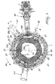
- the device according to the invention is meant to be fitted on a circular knitting machine or hosiery knitting machine, of the single-cylinder type, which comprises a sinker ring 1, which is fixed coaxially to the needle cylinder 2 at its upper end, and a sinker cap 3, which faces in an upward region the sinker ring 1.
- the sinker ring 1 can be actuated so as to rotate about its own axis 1a, which coincides with the axis of the needle cylinder 2, rigidly with the needle cylinder 2, with respect to the sinker cap 3.
- a plurality of radial slots 4 are formed in the sinker ring 1; each slot slidingly accommodates a sinker 5, which is provided with at least one heel 5a, which protrudes upwardly from the corresponding radial slot 4 and can engage sinker actuation cams 6, which face the sinker ring 1 in an upward region.
- the sinker actuation cams 6 are associated with the sinker cap 3 and define paths for the heels 5a of the sinkers 5.
- the device according to the invention comprises, for each one of the radial slots 4, a selector 10, which faces the end of the corresponding radial slot 4 that is directed away from the axis 1a of the sinker ring 1.
- the selector 10 can oscillate on a radial plane with respect to the sinker ring 1 in order to pass from an inactive position to an active position or vice versa.
- the selector 10 is connected to the corresponding sinker 5, which is arranged in the corresponding radial slot 4, in order to produce a different actuation of the corresponding sinker 5 along the corresponding radial slot 4, depending on whether the selector 10 is in the inactive position or in the active position, as will become better apparent hereinafter.
- the device according to the invention further comprises a selection actuator 11, which laterally faces the sinker ring 1 and can engage on command the selector 10 in order to transfer it from the inactive position to the active position.
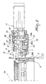
- the selector 10 has a flattened shape and is accommodated inside an extension of the corresponding radial slot 4 that runs along the lateral face of the sinker ring 1 that is directed away from the axis 1a.
- Said selector 10 has an elongated shape and is arranged substantially parallel to the axis 1a except for the inclination that is induced, with respect to said axis, in the transfer from the inactive position to the active position.
- the selector 10 can oscillate on its plane of arrangement, i.e., on a radial plane with respect to the sinker ring 1, about a selector axis 10a that is arranged proximate to the lower end of the selector.
- the lower end of the selector 10 has a circular profile that is coupled rotationally within a seat 12, which is formed inside a supporting ring 13 arranged coaxially to the sinker ring 1.
- the supporting ring 13 is fixed to the sinker cap 3, and a bearing 14 is interposed between the supporting ring 13 and the sinker ring 1.
- the selectors 10 are coupled in the seat 12 so that they can slide circumferentially about the axis 1a of the sinker ring 1, so that the selectors 10 follow the sinker ring 1 in its rotary motion about the axis 1a, sliding in the seat 12 of the supporting ring 13, which remains stationary, during this rotation, with the sinker cap 3.
- the selector 10 has, on its side directed away from the axis 1a of the sinker ring 1, at least one selection heel 15, which can be selectively engaged, i.e. engaged or not by the selection actuator 11 in order to transfer the selector 10 from the inactive position to the active position or to keep the selector 10 in the inactive position.
- Contiguous selectors 10 with which the sinker ring 1 is fitted have selection or selector heels 15 arranged at mutually different heights in order to allow, if required, a different intervention of the selection actuator 11 on contiguous selectors 10.
- the selection actuator 11 is provided with selection levers 16 arranged at mutually different heights so as to match the heights of the selection heels 15. Said selection levers 16 can move on command in order to interfere or not with the corresponding selection heels 15, depending on whether one wishes to move the corresponding selectors 10 into the active position or keep the selectors 10 in the inactive position.
- the selection levers 16 can be controlled and actuated, in order selectively interfere, i.e. to interfere or not with the corresponding selection heels 15, by way of mechanical, magnetic, pneumatic, electromagnetic means or other known actuation means, and can be provided so as to be able to perform a translational motion or an oscillation, such as the one shown, according to the requirements.
- the selection actuator 11 is functionally connected to an electronic actuation and control element, not shown for the sake of simplicity, which supervises the operation of the entire machine and actuates the selection levers 16 so that they interfere or not with the selection heels 15, according to preset work programs.
- each selector 10 is connected to the corresponding sinker 5 by way of a pusher 20, which is arranged in the corresponding radial slot 4 of the sinker ring 1 and is interposed between the selector 10 and the corresponding sinker 5.
- Said pusher 20 has a heel 20a, which protrudes upwardly from the corresponding slot 4 of the sinker ring 1 and can engage pusher actuation cams 21 that face in an upward region the sinker ring 1 and are associated with the sinker cap 3.
- the pusher 20 has a portion that protrudes toward the axis 1a of the sinker ring 1 and is arranged between the bottom of the corresponding radial slot 4 and the base of the corresponding sinker 5. More particularly, the pusher 20 is preferably substantially L-shaped, with an arm 20b of the L-shape that rests on the bottom of the corresponding radial slot 4 and with the other arm 20c of the L-shape that rises from the bottom of the corresponding radial slot 4 and faces the corresponding selector 10. This arm 20c of the pusher 20 ends, at its end that is directed upwardly, with the heel 20a, which preferably tapers upwardly.
- the pusher actuation cams 21 comprise a first cam 30, which is arranged proximate to the selection actuator 11 and is provided with two active profiles: a first active profile 30a, which is directed toward the axis 1a, and a second active profile 30b, which is directed away from the axis 1a.
- the first active profile 30a defines the first path for the heel 20a of the pushers 20 and is engaged by the heels 20a of the pushers 20 whose corresponding selector 10 is in the active position
- the second active profile 30b defines the second path for the heels 20a of the pushers 20, which is engaged by the heels 20a of the pushers 20 whose selectors 10 are in the inactive position.
- the corresponding pushers 20 act on the sinkers 5, causing, during a step of the forming of the knitting, a greater advancement of the sinkers 5 toward the axis 1a, which forms toweling stitches, while the pushers 20 that engage, with their heel 20a, the second active profile 30b have no effect on the sinkers 5, which are actuated exclusively by the cams 6 usually provided on the knitting machine or hosiery knitting machine in order to form plain stitches or other stitches different from toweling stitches.
- the cams for actuating the pushers 20 comprise a reset cam 31, which is arranged downstream of the first cam 30 along the direction of rotation 40 of the sinker ring 1 with respect to the sinker cap 3 and has an active profile 31a that moves gradually away from the axis 1a.
- This active profile 31a of the cam 31 can be engaged exclusively by the heels 20a of the pushers 20 that followed the first active profile 30a of the cam 30, and is meant to move the corresponding pushers 20 away from the axis 1a until the corresponding selector 10 is moved from the active position to the inactive position in order to undergo again selection on the part of a selection actuator 11.
- the embodiment shown relates to a circular hosiery knitting machine with two feeds, with a selection actuator 11 arranged at a feed of the machine that is used both in the rotation of the needle cylinder about its own axis in one direction 40 and in an opposite direction 50, and with another selection actuator 111 that is arranged at another feed or drop of the machine.
- the pusher actuation cams 21 which are each constituted by a first cam 30, 130 and by a reset cam 31, 131, which are arranged substantially symmetrically with respect to a radial plane 41 of the sinker ring 1 that passes through the drop or feed of the machine that is used to feed the needles 7 in both directions of rotation 40, 50 of the needle cylinder 2 about the axis 1a.
- the selection actuator 11 is arranged at said feed or drop of the machine, so that the selection, i.e., the intervention or not of the selection levers 16 on the selection heels 15 of the selectors 10, occurs substantially at said radial plane 41.
- the machine can be equipped with a known type of device 42 that can adjust the position of the sinker cap 3 and therefore of the actuation cams associated therewith about the axis 1a, so as to anticipate or delay, according to the requirements, the intervention of said actuation cams on the elements, i.e., the sinkers 4 and the pushers 20, that are actuated by said cams, depending on the work requirements.
- a known type of device 42 that can adjust the position of the sinker cap 3 and therefore of the actuation cams associated therewith about the axis 1a, so as to anticipate or delay, according to the requirements, the intervention of said actuation cams on the elements, i.e., the sinkers 4 and the pushers 20, that are actuated by said cams, depending on the work requirements.
- pusher actuation cams 230 and 231 are associated with the sinker cap 3.
- the operation of the device is described with reference to the feed or drop of the machine that is served by the selection actuator 11, while the needle cylinder 2 and the sinker ring 1 rotate in the direction 40; it is understood that similar operation occurs at the feed or drop that is served by the selection actuator 111.
- the selection actuator 11 does not act with its selection levers 16 on the selection heel 15 of the corresponding selector 10. In this manner, the selector 10 remains in the inactive position and the corresponding sinker 5 is actuated in a per se known manner, exclusively by means of the sinker actuation cams 6. In this condition, in fact, the pusher 20 passes with its heel 20a over the second active profile 30b of the first cam 30 and therefore has no effect on the movement of the corresponding sinker 5, as shown in Figures 1 and 2 .
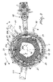
- the selection actuator 11 acts, with a selection lever 16, on the selection heel 15 of the corresponding selector 10, so as to transfer the selector 10 from the inactive position to the active position.
- the pusher 20 moves toward the axis 1a of the sinker ring 1 and passes with its heel 20a over the first active profile 30a of the first cam 30.
- the profile 30a produces the further translational motion of the pusher 20 toward the axis 1a, which pushes the corresponding sinker 5 toward the axis 1a more than the displacement that the sinker 5 would undergo exclusively by means of the sinker actuation cams 6, as shown in Figures 3 and 4 .
- the heel 20a of the pushers 20 that have passed over the first active profile 30a then engage the reset cam 31, which moves said pushers 20 away from the axis 1a, returning the pushers 20 to the initial condition and the corresponding selectors 10 to the inactive position, ready to be selected again by means of a subsequent selection actuator, for example the actuator 111 in Figures 1 and 3 .
- a kind of operation similar to the one just described occurs when the needle cylinder 2 and the sinker ring are actuated in the direction of rotation 50.
- the cams that act on the pushers 20 are constituted by the cams 130 and 131, which are similar to the cams 30 and 31.
- the device according to the invention fully achieves the intended aim and objects, since it allows to perform individual selection of the sinkers despite using sinkers of a conventional type.
- the selection device according to the invention has been described with reference to a selection of the sinkers actuated to form toweling stitches or stitches that are different from toweling stitches; however, the selection device according to the invention can also be used to obtain a diversified movement of the sinkers for other kinds of work, such as for example vanisé work.
- the materials used, as well as the dimensions, may be any according to requirements and to the state of the art.
Landscapes
- Engineering & Computer Science (AREA)
- Textile Engineering (AREA)
- Knitting Machines (AREA)
Claims (11)
- Eine Vorrichtung zur Platinenauswahl in einer Rundstrickmaschine für Strumpfwaren oder dergleichen, von der Art, die einen Platinenring (1) umfasst, welcher koaxial an seinem oberen Ende mit dem Nadelzylinder (2) verknüpft ist, und eine Platinenkappe (3), die in einem oberen Bereich zu dem Platinenring (1) hin weist, wobei der Platinenring (1) mit einer Drehbewegung um seine eigene Achse (1a) herum in Bezug zur Platinenkappe (3) betätigt werden kann, wobei eine Vielzahl von radialen Schlitzen (4) in dem Platinenring (1) geformt sind, wobei jeder der Schlitze (4) verschiebbar eine Platine (5) aufnimmt, die mindestens eine Fase (5a) hat, welche aufwärts aus dem entsprechenden radialen Schlitz (4) herausragt und welche in Platinen-Betätigungsnocken (6) eingreifen kann, die in einem oberen Bereich zu dem Platinenring (1) hin weisen und die mit der Platinenkappe (3) verküpft sind, und für jeden der radialen Schlitze (4) einen Selektor (10) umfassend, der dem Ende des entsprechenden radialen Schlitzes (4) gegenüberliegt, das von der Achse (1a) des Platinenrings (1) fort gerichtet ist, wobei der Selektor (10) auf einer radialen Ebene in Bezug zum Platinenring (1) oszillieren kann, um aus einer aktiven Position in eine inaktive Position zu wechseln oder umgekehrt, und mit der entsprechenden Platine (5) verbunden ist, die in dem entsprechenden radialen Schlitz (4) angeordnet ist, um eine andere Betätigung der entsprechenden Platine (5) entlang dem entsprechenden radialen Schlitz (4) herbeizuführen, je nachdem, ob der Selektor (10) sich in der inaktiven Position oder in der aktiven Position befindet, wobei ein Selektions-Betätigungselement (11) bereitgestellt ist, das seitlich dem Platinenring (1) gegenüberliegt und auf Befehl in den Selektor (10) eingreifen kann, um ihn aus der inaktiven Position in die aktive Position zu bringen, wobei der Selektor (10) eine verlängerte Form hat, die im Wesentlichen parallel zur Achse (1a) des Platinenrings (1) verläuft, dadurch gekennzeichnet, dass der Selektor auf der radialen Ebene in Bezug zum Platinenring (1) um eine Achse (10a) oszillieren kann, die in der Nähe des unteren Endes des Selektors (10) angeordnet ist; dadurch, dass der Selektor (10) mit der entsprechenden Platine (5) durch einen Vorschubschieber (20) verbunden ist, welcher in dem entsprechenden radialen Schlitz (4) des Platinenrings (1) angeordnet ist und zwischen dem Selektor (10) und der entsprechenden Platine (5) zwischengeordnet ist; und dadurch, dass der Vorschubschieber (20) eine Fase (20a) hat, die aufwärts aus dem entsprechenden radialen Schlitz (4) des Platinenrings (1) herausragt und in Vorschubschieber-Betätigungsnocken (21) eingreifen kann, welche in einem oberen Bereich dem Platinenring (1) gegenüberliegen und mit der Platinenkappe (3) verküpft sind.
- Die Vorrichtung gemäß Anspruch 1, dadurch gekennzeichnet, dass die Vorschubschieber-Betätigungsnocken (21) mindestens zwei verschiedene Wege für die Fase (20a) des Vorschubschiebers (20) bestimmen, einen ersten Weg beziehungsweise einen zweiten Weg, in welche die Fase (20a) des Vorschubschiebers (20) selektiv eingreifen kann, je nachdem, ob der Selektor (10), der auf den Vorschubschieber (20) einwirkt, sich in der aktiven Position oder in der inaktiven Position befindet.
- Die Vorrichtung gemäß einem oder mehreren der Ansprüche 1-2, dadurch gekennzeichnet, dass der Vorschubschieber (20) einen Abschnitt hat, der zur Achse (1a) des Platinenrings (1) hin herausragt und zwischen dem Boden des entsprechenden radialen Schlitzes (4) und der Basis der entsprechenden Platine (5) angeordnet ist.
- Die Vorrichtung gemäß einem oder mehreren der obigen Ansprüche, dadurch gekennzeichnet, dass der Vorschubschieber (20) im Wesentlichen L-förmig ist, wobei ein Arm (20b) der L-Form auf dem Boden des entsprechenden radialen Schlitzes (4) ruht und der andere Arm (20c) der L-Form aus dem Boden des entsprechenden radialen Schlitzes (4) herausragt und dem entsprechenden Selektor (10) gegenüberliegt.
- Die Vorrichtung gemäß einem oder mehreren der obigen Ansprüche, dadurch gekennzeichnet, dass die Fase (20a) des Vorschubschiebers (20) eine Form hat, die nach oben spitz zuläuft.
- Die Vorrichtung gemäß einem oder mehreren der obigen Ansprüche, dadurch gekennzeichnet, dass der Selektor (10) auf der Seite, die von der Achse des Platinenrings (1) fort gerichtet ist, mindestens eine Selektions-Fase (15) hat, in welche das Selektions-Betätigungselement (11) eingreifen kann oder nicht, um den Selektor (10) aus der inaktiven Position in die aktive Position zu bewegen oder den Selektor (10) in der inaktiven Position zu lassen.
- Die Vorrichtung gemäß einem oder mehreren der obigen Ansprüche, dadurch gekennzeichnet, dass benachbarte Selektoren (10) Selektions-Fasen (15) haben, die in verschiedenen Höhen zueinander angeordnet sind, wobei das Selektions-Betätigungselement (11) mit Selektions-Hebeln (16) ausgestattet ist, die in verschiedenen Höhen zueinander angeordnet sind, um den Höhen der Selektions-Fasen (15) zu entsprechen, wobei die Selektions-Hebel (16) auf Befehl bewegt werden können, um mit den entsprechenden Selektions-Fasen (15) zu interferieren oder nicht.
- Die Vorrichtung gemäß einem oder mehreren der obigen Ansprüche, dadurch gekennzeichnet, dass die Vorschubschieber-Betätigungsnocken (21) mindestens einen Rückstellnocken (31) umfassen, der entlang dem ersten Weg der Fase des Vorschubschiebers angeordnet ist und der in die Fase (20a) des Vorschubschiebers (20) eingreifen kann, um den Vorschubschieber (20) von der Achse (1a) des Platinenrings (1) fort zu bewegen, und zwar mit einer daraus folgenden Oszillation des entsprechenden Selektors (10) von der aktiven Position in die inaktive Position.
- Die Vorrichtung gemäß einem oder mehreren der obigen Ansprüche, dadurch gekennzeichnet, dass sie mindestens zwei Sätze von Vorschubschieber-Betätigungsnocken (21) umfasst, die im Wesentlichen symmetrisch zu einer radialen Ebene (41) des Platinenrings (1) angeordnet sind, welche sich durch einen Abwurf oder Vorschub der Maschine erstreckt.
- Die Vorrichtung gemäß einem oder mehreren der obigen Ansprüche, dadurch gekennzeichnet, dass das Selektions-Betätigungselement (11) an einem Abwurf oder Vorschub der Maschine angeordnet ist, der in beide Drehrichtungen (40, 50) des Platinenrings (1) und des Nadelzylinders (2) um ihre eigene Achse (1a) herum verwendet werden kann.
- Die Vorrichtung gemäß einem oder mehreren der obigen Ansprüche, dadurch gekennzeichnet, dass das untere Ende des Selektors (10) ein kreisförmiges Profil hat und so angeordnet ist, dass er in Umfangsrichtung um die Achse (1a) des Platinenrings (1) herum in einem Sitz (12) gleiten kann, der in Umfangsrichtung in einem Stützring (13) liegt, welcher mit der Platinenkappe (3) verbunden ist.
Applications Claiming Priority (2)
| Application Number | Priority Date | Filing Date | Title |
|---|---|---|---|
| ITMI20031995 | 2003-10-15 | ||
| IT001995A ITMI20031995A1 (it) | 2003-10-15 | 2003-10-15 | Dispositivo per la selezione delle platine di abbattitura in una macchina circolare per maglieria, calzetteria o simile |
Publications (2)
| Publication Number | Publication Date |
|---|---|
| EP1524348A1 EP1524348A1 (de) | 2005-04-20 |
| EP1524348B1 true EP1524348B1 (de) | 2009-11-11 |
Family
ID=34362416
Family Applications (1)
| Application Number | Title | Priority Date | Filing Date |
|---|---|---|---|
| EP04021033A Expired - Lifetime EP1524348B1 (de) | 2003-10-15 | 2004-09-03 | Vorrichtung zur Platinenauswahl in einer Rundstrickmaschine zum Stricken von Strumpfwaren oder dergleichen |
Country Status (4)
| Country | Link |
|---|---|
| US (1) | US7065989B2 (de) |
| EP (1) | EP1524348B1 (de) |
| JP (1) | JP4628063B2 (de) |
| IT (1) | ITMI20031995A1 (de) |
Families Citing this family (8)
| Publication number | Priority date | Publication date | Assignee | Title |
|---|---|---|---|---|
| CN103255562B (zh) * | 2012-02-15 | 2015-11-25 | 冈本株式会社 | 线圈尺寸可控的针织机及针织面料的制造方法 |
| EP2708624A1 (de) * | 2012-09-14 | 2014-03-19 | Pai Lung Machinery Mill Co., Ltd. | Kreisstrickmaschine mit feiner Spurweite |
| KR101495543B1 (ko) * | 2013-04-30 | 2015-03-04 | 용원주 | 실린더형 편직기의 니들하강장치 |
| IT201900005888A1 (it) * | 2019-04-16 | 2020-10-16 | Santoni & C Spa | Macchina circolare per maglieria e procedimento per la formazione di punti spugna in una macchina circolare per maglieria |
| IT201900005896A1 (it) * | 2019-04-16 | 2020-10-16 | Santoni & C Spa | Macchina circolare per maglieria |
| IT201900005900A1 (it) * | 2019-04-16 | 2020-10-16 | Santoni & C Spa | Metodo per la realizzazione di tessuto a maglia traforato su una macchina circolare per maglieria |
| IT201900005892A1 (it) * | 2019-04-16 | 2020-10-16 | Santoni & C Spa | Macchina circolare per maglieria per la realizzazione di tessuto a maglia traforato |
| IT202100018056A1 (it) * | 2021-07-08 | 2023-01-08 | Santoni & C Spa | Macchina tessile circolare per maglieria e relativo metodo di formazione della maglia |
Family Cites Families (10)
| Publication number | Priority date | Publication date | Assignee | Title |
|---|---|---|---|---|
| US2207463A (en) * | 1929-09-16 | 1940-07-09 | Hemphill Co | Selective control of sinkers, needles, and jacks |
| GB462662A (en) * | 1935-08-12 | 1937-03-12 | Leslie Herbert Leedham | Improvements in or relating to knitting machines |
| IT1104303B (it) * | 1978-12-21 | 1985-10-21 | Conti Gianni | Macchina da maglieria con aghisenza paletta cooperanti con elementi ad uncino esterni |
| IT1240008B (it) * | 1990-04-27 | 1993-11-27 | Lonati Srl | Macchina circolare per maglieria, calzetteria, o simile, con dispositivo di comando delle platine di abbattitura |
| IT1241778B (it) * | 1990-08-23 | 1994-02-01 | Conti Florentia Srl | Dispositivo con doppia serie di platine e doppia custodia platine per la costruzione di tessuto a spugna con macchine circolari a moto alternato |
| FR2706491B1 (fr) * | 1993-06-17 | 1995-07-28 | Chomarat Textiles Plastiques | Procédé et installation pour la réalisation d'un tricot velours jacquard sur un métier circulaire et nouveau type de tricot ainsi réalisé. |
| US6105402A (en) * | 1995-10-24 | 2000-08-22 | Lee; Kyung-Mok | Design of sinker and sinker cam shape for a circular knitting machine and method for patterning fabric with the combination of an actuator and these newly designed tools |
| US5931025A (en) * | 1998-05-20 | 1999-08-03 | Santoni S.P.A. | Lowering sinker actuation cam set for circular knitting machines for forming standard-terry knitting and sandwich-terry knitting |
| IT1314727B1 (it) * | 2000-05-10 | 2003-01-03 | Sangiacomo Spa | Dispositivo di selezione delle platine per la costruzione di maglia aspugna disegnata su macchine circolari da maglieria e calzetteria |
| DE10207879A1 (de) * | 2002-02-18 | 2003-08-28 | Sipra Patent Beteiligung | Rundstrickmaschine zur Herstellung von Plüschwaren |
-
2003
- 2003-10-15 IT IT001995A patent/ITMI20031995A1/it unknown
-
2004
- 2004-09-03 EP EP04021033A patent/EP1524348B1/de not_active Expired - Lifetime
- 2004-09-08 US US10/935,758 patent/US7065989B2/en not_active Expired - Lifetime
- 2004-10-14 JP JP2004300367A patent/JP4628063B2/ja not_active Expired - Lifetime
Also Published As
| Publication number | Publication date |
|---|---|
| EP1524348A1 (de) | 2005-04-20 |
| JP2005120567A (ja) | 2005-05-12 |
| ITMI20031995A1 (it) | 2005-04-16 |
| JP4628063B2 (ja) | 2011-02-09 |
| US7065989B2 (en) | 2006-06-27 |
| US20050081569A1 (en) | 2005-04-21 |
Similar Documents
| Publication | Publication Date | Title |
|---|---|---|
| JP3455562B2 (ja) | 多重ヤーン供給円形編機 | |
| EP1524348B1 (de) | Vorrichtung zur Platinenauswahl in einer Rundstrickmaschine zum Stricken von Strumpfwaren oder dergleichen | |
| US4539825A (en) | Device selecting the needles on the dial plate of either single or multiple feed, single cylinder circular knitting machines for the manufacture of ribbed fabric | |
| EP2002040B1 (de) | Rundstrickmaschine für strumpfwaren | |
| US5931025A (en) | Lowering sinker actuation cam set for circular knitting machines for forming standard-terry knitting and sandwich-terry knitting | |
| EP3956510B1 (de) | Rundstrickmaschine mit platinenauswahl und verfahren zur herstellung von strickstoffen mit dieser maschine | |
| EP2002043B1 (de) | Zweizylindrige rundstrickmaschine für miederwaren und andere strickwaren | |
| US6422044B1 (en) | Needle actuation device for knitting machines for hosiery or other articles | |
| CN102108597B (zh) | 在针织机中选择针盘的针的方法和用于实施该方法的针盘 | |
| EP1620591B1 (de) | Rundstrickmaschine, vorzugsweise mit mittlerem durchmesser, mit verbesserter nadelauswahl | |
| EP0547526B1 (de) | Rundstrickmaschine zur Herstellung von Socken, Strümpfen und dergleichen mit Vorrichtung zur Herstellung von Mustern mit Frottiermaschen | |
| US5960645A (en) | Device for selecting needles in circular stocking knitting machines | |
| EP0567880A2 (de) | Rundstrickmachine zur Herstellung von Socken, Strümpfen und dergleichen mit einem verbesserten Strickschlosssystem | |
| EP4211297B1 (de) | Eine formplatine für strickmaschinen, insbesondere zur herstellung von ajourstrickwaren | |
| US6295845B1 (en) | Thread dispensing device for dispensing thread at a feed of a circular knitting machine | |
| EP3956509B1 (de) | Rundstrickmaschine zur herstellung durchbrochener maschenware | |
| EP0328976B1 (de) | Nadelauswahlvorrichtung für eine Strickmaschine | |
| EP0957193B1 (de) | Senkerplatine-Schlosssystem für Rundstrickmaschinen zum Formen von Standard-Schlingengestrick und Sandwich-Schlingengestrick | |
| EP3956508B1 (de) | Rundstrickmaschine und verfahren zur bildung von plüschmaschen in einer rundstrickmaschine | |
| EP0290897A2 (de) | Vorrichtung zum Steuern von Wählern an einer Viersystem-Rundstrickmaschine für Socken und Strümpfe | |
| US6164090A (en) | Needle actuation device for knitting machines | |
| EP0962569A2 (de) | Anpassungsfähige Rundstrickmaschine für Strümpfen oder dergleichen mit mehreren Systemen oder Fadenliefervorrichtungen |
Legal Events
| Date | Code | Title | Description |
|---|---|---|---|
| PUAI | Public reference made under article 153(3) epc to a published international application that has entered the european phase |
Free format text: ORIGINAL CODE: 0009012 |
|
| AK | Designated contracting states |
Kind code of ref document: A1 Designated state(s): AT BE BG CH CY CZ DE DK EE ES FI FR GB GR HU IE IT LI LU MC NL PL PT RO SE SI SK TR |
|
| AX | Request for extension of the european patent |
Extension state: AL HR LT LV MK |
|
| 17P | Request for examination filed |
Effective date: 20050906 |
|
| AKX | Designation fees paid |
Designated state(s): CZ FR PL TR |
|
| REG | Reference to a national code |
Ref country code: DE Ref legal event code: 8566 |
|
| 17Q | First examination report despatched |
Effective date: 20070605 |
|
| GRAP | Despatch of communication of intention to grant a patent |
Free format text: ORIGINAL CODE: EPIDOSNIGR1 |
|
| GRAS | Grant fee paid |
Free format text: ORIGINAL CODE: EPIDOSNIGR3 |
|
| GRAA | (expected) grant |
Free format text: ORIGINAL CODE: 0009210 |
|
| AK | Designated contracting states |
Kind code of ref document: B1 Designated state(s): CZ FR PL TR |
|
| PG25 | Lapsed in a contracting state [announced via postgrant information from national office to epo] |
Ref country code: PL Free format text: LAPSE BECAUSE OF FAILURE TO SUBMIT A TRANSLATION OF THE DESCRIPTION OR TO PAY THE FEE WITHIN THE PRESCRIBED TIME-LIMIT Effective date: 20091111 |
|
| PLBE | No opposition filed within time limit |
Free format text: ORIGINAL CODE: 0009261 |
|
| STAA | Information on the status of an ep patent application or granted ep patent |
Free format text: STATUS: NO OPPOSITION FILED WITHIN TIME LIMIT |
|
| 26N | No opposition filed |
Effective date: 20100812 |
|
| REG | Reference to a national code |
Ref country code: FR Ref legal event code: ST Effective date: 20110531 |
|
| PG25 | Lapsed in a contracting state [announced via postgrant information from national office to epo] |
Ref country code: FR Free format text: LAPSE BECAUSE OF NON-PAYMENT OF DUE FEES Effective date: 20100930 |
|
| PG25 | Lapsed in a contracting state [announced via postgrant information from national office to epo] |
Ref country code: TR Free format text: LAPSE BECAUSE OF FAILURE TO SUBMIT A TRANSLATION OF THE DESCRIPTION OR TO PAY THE FEE WITHIN THE PRESCRIBED TIME-LIMIT Effective date: 20091111 |
|
| P01 | Opt-out of the competence of the unified patent court (upc) registered |
Effective date: 20230526 |
|
| PGFP | Annual fee paid to national office [announced via postgrant information from national office to epo] |
Ref country code: CZ Payment date: 20230818 Year of fee payment: 20 |
|
| PG25 | Lapsed in a contracting state [announced via postgrant information from national office to epo] |
Ref country code: CZ Free format text: LAPSE BECAUSE OF EXPIRATION OF PROTECTION Effective date: 20240903 |
|
| PG25 | Lapsed in a contracting state [announced via postgrant information from national office to epo] |
Ref country code: CZ Free format text: LAPSE BECAUSE OF EXPIRATION OF PROTECTION Effective date: 20240903 |