EP1523820B1 - A fault-tolerant broadcast router - Google Patents
A fault-tolerant broadcast router Download PDFInfo
- Publication number
- EP1523820B1 EP1523820B1 EP03737132A EP03737132A EP1523820B1 EP 1523820 B1 EP1523820 B1 EP 1523820B1 EP 03737132 A EP03737132 A EP 03737132A EP 03737132 A EP03737132 A EP 03737132A EP 1523820 B1 EP1523820 B1 EP 1523820B1
- Authority
- EP
- European Patent Office
- Prior art keywords
- audio data
- digital audio
- data streams
- parity
- router
- Prior art date
- Legal status (The legal status is an assumption and is not a legal conclusion. Google has not performed a legal analysis and makes no representation as to the accuracy of the status listed.)
- Expired - Lifetime
Links
- 239000011159 matrix material Substances 0.000 claims description 123
- 238000000034 method Methods 0.000 claims description 19
- 230000036541 health Effects 0.000 claims description 18
- 230000005540 biological transmission Effects 0.000 claims description 13
- 238000001514 detection method Methods 0.000 claims description 12
- 230000004044 response Effects 0.000 claims description 6
- 230000001902 propagating effect Effects 0.000 claims 4
- 239000000872 buffer Substances 0.000 description 14
- 230000000644 propagated effect Effects 0.000 description 14
- 238000004891 communication Methods 0.000 description 2
- 230000001934 delay Effects 0.000 description 2
- 238000010586 diagram Methods 0.000 description 2
- 238000012986 modification Methods 0.000 description 2
- 230000004048 modification Effects 0.000 description 2
- 238000012546 transfer Methods 0.000 description 2
- RYGMFSIKBFXOCR-UHFFFAOYSA-N Copper Chemical compound [Cu] RYGMFSIKBFXOCR-UHFFFAOYSA-N 0.000 description 1
- 235000014121 butter Nutrition 0.000 description 1
- 238000010835 comparative analysis Methods 0.000 description 1
- 238000012937 correction Methods 0.000 description 1
- 230000008878 coupling Effects 0.000 description 1
- 238000010168 coupling process Methods 0.000 description 1
- 238000005859 coupling reaction Methods 0.000 description 1
- 125000004122 cyclic group Chemical group 0.000 description 1
- 230000007547 defect Effects 0.000 description 1
- 238000003780 insertion Methods 0.000 description 1
- 230000037431 insertion Effects 0.000 description 1
- 239000013307 optical fiber Substances 0.000 description 1
- 230000008569 process Effects 0.000 description 1
- 230000008439 repair process Effects 0.000 description 1
- 230000001360 synchronised effect Effects 0.000 description 1
Images

Classifications
-
- H—ELECTRICITY
- H04—ELECTRIC COMMUNICATION TECHNIQUE
- H04L—TRANSMISSION OF DIGITAL INFORMATION, e.g. TELEGRAPHIC COMMUNICATION
- H04L1/00—Arrangements for detecting or preventing errors in the information received
- H04L1/22—Arrangements for detecting or preventing errors in the information received using redundant apparatus to increase reliability
-
- H—ELECTRICITY
- H04—ELECTRIC COMMUNICATION TECHNIQUE
- H04L—TRANSMISSION OF DIGITAL INFORMATION, e.g. TELEGRAPHIC COMMUNICATION
- H04L1/00—Arrangements for detecting or preventing errors in the information received
- H04L1/004—Arrangements for detecting or preventing errors in the information received by using forward error control
- H04L1/0056—Systems characterized by the type of code used
- H04L1/0061—Error detection codes
-
- H—ELECTRICITY
- H04—ELECTRIC COMMUNICATION TECHNIQUE
- H04L—TRANSMISSION OF DIGITAL INFORMATION, e.g. TELEGRAPHIC COMMUNICATION
- H04L45/00—Routing or path finding of packets in data switching networks
- H04L45/60—Router architectures
-
- H—ELECTRICITY
- H04—ELECTRIC COMMUNICATION TECHNIQUE
- H04L—TRANSMISSION OF DIGITAL INFORMATION, e.g. TELEGRAPHIC COMMUNICATION
- H04L12/00—Data switching networks
- H04L12/02—Details
- H04L12/16—Arrangements for providing special services to substations
- H04L12/18—Arrangements for providing special services to substations for broadcast or conference, e.g. multicast
- H04L12/1863—Arrangements for providing special services to substations for broadcast or conference, e.g. multicast comprising mechanisms for improved reliability, e.g. status reports
- H04L12/1868—Measures taken after transmission, e.g. acknowledgments
-
- H—ELECTRICITY
- H04—ELECTRIC COMMUNICATION TECHNIQUE
- H04L—TRANSMISSION OF DIGITAL INFORMATION, e.g. TELEGRAPHIC COMMUNICATION
- H04L49/00—Packet switching elements
- H04L49/20—Support for services
- H04L49/201—Multicast operation; Broadcast operation
-
- H—ELECTRICITY
- H04—ELECTRIC COMMUNICATION TECHNIQUE
- H04L—TRANSMISSION OF DIGITAL INFORMATION, e.g. TELEGRAPHIC COMMUNICATION
- H04L49/00—Packet switching elements
- H04L49/20—Support for services
- H04L49/205—Quality of Service based
- H04L49/206—Real Time traffic
-
- H—ELECTRICITY
- H04—ELECTRIC COMMUNICATION TECHNIQUE
- H04L—TRANSMISSION OF DIGITAL INFORMATION, e.g. TELEGRAPHIC COMMUNICATION
- H04L49/00—Packet switching elements
- H04L49/55—Prevention, detection or correction of errors
- H04L49/557—Error correction, e.g. fault recovery or fault tolerance
Definitions
- the present invention relates to broadcast routers and, more particularly, to a fault-tolerant broadcast router configured to detect an error in a first output data stream and automatically switch to a second output data stream in response to the detection of the error in the first output data stream.
- a broadcast router allows each one of a plurality of outputs therefrom to be assigned the signal from any one of a plurality of inputs thereto.
- an N x M broadcast router has N inputs and M outputs coupled together by a router matrix which allows any one of the N inputs to be applied to each one of the M outputs, While failure of any one or more of the various components, e.g., input cards, output cards, router matrix, interconnecting cables or power supply, of a broadcast router may cause a defect in the output of the router, failure of the router matrix can be particularly catastrophic since all signals for the broadcast router typically flow through the router matrix.
- broadcast routers By configuring a broadcast router to include both a first, or primary, router matrix in combination with a second, or redundant, router matrix, broadcast routers have achieved a limited degree of fault tolerance.
- broadcast routers which incorporate a redundant router matrix have typically relied upon the use of an alarm or other type of alert to notify an operator of the broadcast router that the primary router matrix has failed and a manual switch or other type of operator-actuated device to switch the output of the broadcast router from that of the failed primary router matrix to that of the redundant router matrix.
- US-A-5 268 909 relates to a method for reducing bit errors in digital communication systems. Bit falsifications that can occur in the through-connection of bit streams composed of a plurality of information words are identified with a combine purity check and a bit-by-bit comparison of information words that are through-connected in parallel.
- US 6 246 681 B1 provides a system for selecting one of two or more parallel planes of data is provided.
- the system includes a first data buffer that is connected to a first data bus that carries a stream of datagrams.
- the first data butler receives and stores datagrams from the first data bus.
- the system also includes a second data buffer that is connected to a second data bus that carries a stream of datagrams.
- the second data buffer receives and stores datagrams from the second data bus.
- a selection controller connected to the first data buffer and the second data buffer analyzes the datagrams stored in the first and second data buffers, and selects one of the datagrams to be the primary datagram.
- WO01/59978A discloses methods and apparatus for selecting the better of two or more copies of a cell in a cell/oriented redundant switching system connected to an external communication network.
- the best cell copy selection aligns redundantly transmitted cell streams before selecting cells for insertion in the data stream. Because the streams are aligned before the selection is made, the best cell copy selector compares each cell at the same instant in time, rather than basing its selection on past events.
- a system for selecting one of two or more parallel planes of data includes a first data butter that is connected to a first data bus that carries a steam of datagrams.
- the first data buffer receives and stores datagrams from the first data bus.
- the system also includes a second data buffer that is connected to a second data bus that carries a stream of datagrams.
- the seconde data buffer receives and stores datagrams from the second data bus.
- a selection controller connected to the first data buffer and the second data buffer analyzes the datagrams stored in the first and second data buffers, and selects one of the datagrams to be the primary datagram.
- a fault-tolerant router includes first and second router matrices and circuitry for selectively switching the output of the fault-tolerant router from a first set of digital output audio data streams generated by the first router matrix and a second set of digital output audio data streams generated by the second router matrix. Switching between the first and second set of digital output audio data streams may be initiated in response to detection of parity error in one of the digital output audio data streams, a comparison of health or status information for the respective digital output audio data streams or both.
- the fault tolerant broadcast router 100 is comprised of plural broadcast router components coupled to one another to form the larger fault tolerant broadcast router 100.
- each one of the broadcast router components used to construct the fault tolerant broadcast router 100 is an N x M sized broadcast router.
- the fault tolerant broadcast router 100 is formed by coupling together first, second, third and fourth broadcast router components 102, 104, 106 and 108.
- first, second, third and fourth broadcast router components 102, 104, 106 and 108 are purely by way of example. Accordingly, it should be clearly understood that a fault tolerant broadcast router constructed in accordance with the teachings of the present invention may be formed using various other numbers of broadcast router components.
- the first, second, third and fourth broadcast router components 102, 104, 106 and 108 which, when fully connected in the manner disclosed herein, collectively form the fault tolerant broadcast router 100, may either be housed together in a common chassis as illustrated in FIG. 1 or, if desired, housed in separate chassis.
- each one of the broadcast router components 102, 104, 106 and 108 have the same N x M size, it is fully contemplated that the broadcast router components 102, 104, 106 and 108 may have different sizes relative to one another. Furthermore, while it is also contemplated that the broadcast router components 102, 104, 106 and 108 may be constructed in various sizes, one size that has proven suitable for the uses contemplated herein is 256 x 256.
- first broadcast router component 102, the second broadcast router component 104, the third broadcast router component 106 and the fourth broadcast router component 108 are coupled together in an arrangement which conforms to a fully connected topology.
- each broadcast router of an arrangement of broadcast routers is coupled, by a discrete link, to each and every other broadcast router forming part of the arrangement of broadcast routers.
- first, second and third bi-directional links 110, 112 and 114 couple the first broadcast router component 102 to the second broadcast router component 104, the third broadcast router component 106 and the fourth broadcast router component 108, respectively.
- fourth and fifth bi-directional links 116 and 118 couple the second broadcast router component 104 to the third broadcast router component 106 and the fourth broadcast router component 108, respectively.
- a sixth bi-directional link 120 couples the third broadcast router component 106 to the fourth broadcast router component 108.
- the bi-directional links 110 through 120 may be formed of copper wire, optical fiber or another transmission medium deemed suitable for the exchange of digital signals.
- the broadcast router components may instead be coupled to one another by pairs of uni-directional links.
- each broadcast router component is a discrete router device which includes first and second router matrices, the second router matrix being redundant of the first router matrix such that one of the first and second router matrices may replace the other one of the first and second router matrices in the event of a failure thereof.
- the first router matrices are arranged in a first fully connected topology.
- the second router matrices being arranged in a second fully connected topology.
- broadcast router component 102, 104, 106 and 108
- the broadcast router components 102, 104, 106 and 108 may instead be used with other low bandwidth digital signals such as compressed video and data signals.
- the broadcast router components may be used with non-compressed digital video signals.
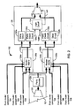
- FIG. 2 shows the first broadcast router component 102.
- the second, third and fourth broadcast router components 104, 106 and 108 are identically configured to the first broadcast router 102. Accordingly, the second, third and fourth broadcast router components 104, 106 and 108 need not be described in greater detail.
- the first broadcast router component 102 includes a first router matrix card 122a and a second router matrix card 122b identically configured to the first router matrix card 122a.
- the first and second router matrix cards 122a and 122b are each slideably received within and supportably mounted by a chassis (not shown) of the broadcast router 100.
- the use of plural router matrix cards is generally preferred since it facilitates the repair and/or replacement of a failed router matrix card without disturbing a properly functioning router matrix card.
- an input card 121 and an output card 128 are also slideably received within and supportably mounted by the chassis.
- the input card 121 is coupled to each one of the first and second router matrix cards 122a and 122b.
- the output card 128 is coupled to each one of the first and second router matrix cards 122a and 122b.
- discrete input and output cards 121 and 128 are shown in FIG. 2 , it should be clearly understood that, if desired, the functionality residing on both the input card 121 and the output card 128 may instead be placed on a single, input/output (or "I/O") card.
- FIG. 2 While FIG. 2 , it should be clearly understood that, if desired, the functionality residing on both the input card 121 and the output card 128 may instead be placed on a single, input/output (or "I/O") card.
- FIG. 1 input/output
- the input signal selection circuitry 123 selects, from plural input signals (not shown) thereto, N input signals to be passed to the parity encoder 126,
- N input signals to be passed to the parity encoder 126.
- the input signal selection circuitry 123 has been greatly simplified for ease of description and that various components thereof have been omitted from the drawings, It should be further understood that the input signal selection circuitry 123 has been shown as residing on a single input card, specifically, the input card 121, purely for ease of illustration and it is fully contemplated that the input signal selection circuitry 123 may instead be distributed amongst plural input cards (also not shown).
- parity encoder 126 is shown as residing on the input card 121, it is fully contemplated that the parity encoder may be placed at a wide variety of locations on the path along which the audio data is propagated. For example, if desired, a parity encoder may be placed on each one of the first and second router cards 122a and 122b and coupled to receive the M digital outputs from the first and second router matrices 124a and 124b, respectively.
- the N input digital audio data streams are propagated to the parity encoder circuits 126.
- the parity encoder circuit processes the data received thereby to include parity information. It is contemplated that a wide variety of algorithms may be used to encode the received input digital audio data streams with parity information.
- the first and second parity encoder circuits 126a and 126b may be configured to add a byte of parity information to each data frame and a frame of parity information for each 32 input data streams in the manner described and illustrated in co-pending U.S. Patent Application No. 2005-0193319 filed June 17, 2003 .
- the number of parity encoded data streams output the parity encoder circuit 126 will vary based upon the number of input data streams.
- the parity encoder 126 will produce 264 parity encoded data streams from 256 input data streams.
- CRC cyclic redundancy check
- checksum checksum
- parity encoded digital audio data streams 1 through N are propagated to both a first router matrix 124a which resides on the first router matrix card 122a and to a second router matrix 124b which resides on the second router matrix card 122b. Additionally, the first and second router matrices 124a and 124b receive input digital audio data streams N+1 through 2N from the second broadcast router component 104, input digital audio data streams 2N+1 through 3N from the third broadcast router component 106 and input digital audio data streams 3N+1 through 4N from the fourth broadcast router component 108.
- input digital audio streams N+1 through 4N are all parity encoded, preferably prior to transmission to the first router matrix 124a of the first router matrix card 122a and to the second router matrix 124b of the second router matrix card 124b. While it is fully contemplated that a variety of broadcast router configurations which include plural router matrices having identical inputs to each router matrix would be suitable for the purposes contemplated herein, one such broadcast router is disclosed in co-pending U.S. Patent Application No. 2006-0120342 filed June 13, 2003 .
- a broadcast router having four broadcast router components, each including a pair of router matrices coupled to receive input digital audio data streams 1 through 4N is described in great detail.
- each one of the first and second router matrix cards 122a and 122b are plural expansion ports (not shown), the configuration of which are also described in greater detail in the aforementioned patent application.
- the expansion ports residing on the first router matrix card 122a are used to buffer the transfer of input digital audio data streams between the first router matrix card 122a and the first router matrix cards of the second, third and fourth broadcast router components 104, 106 and 108.
- the expansion ports residing on the second router matrix card 122b are used to buffer the transfer of input digital audio data streams between the second router matrix card 122b and the second router matrix cards of the second, third and fourth broadcast router components 104, 106 and 108.
- Similar expansion port configurations are provided for the same purpose on each router matrix card of the second, third and fourth broadcast router component 104, 106 and 108.
- each of the first and second router matrix cards 122a and 122b would have first, second and third bi-directional expansion ports residing thereon.
- Each of the first, second and third expansion ports residing on either the router matrix card 122a or 122b would receive the same input digital audio data streams 1 through N as the router matrix 124a or 124b residing on that card.
- the input digital audio streams 1 through N are propagated to the first router matrix card of the second, third and fourth broadcast router components 104, 106 and 108.
- the input digital audio data streams 1 through N are propagated to the second router matrix card of the second, third and fourth broadcast router components 104, 106 and 108.
- first, second and third expansion ports of the first router matrix card 122a would also receive the input digital audio data streams N+1 through 2N, 2N+1 through 3N and 3N+1 through 4N from the first router matrix card of the second, third and fourth broadcast router components 104, 106 and 108, respectively, for subsequent propagation to the router matrix 124a.
- first, second and third expansion ports of the second router matrix card 122b would also receive the input digital audio data streams N+1 through 2N, 2N+1 through 3N and 3N+1 through 4N from the second router matrix card of the second, third and fourth broadcast router components 104, 106 and 108, respectively, for subsequent propagation to the router matrix 124b.
- each of the first and second router matrix cards 122a and 122b would plural unidirectional expansion ports, more specifically, a transmit expansion port and first, second and third receive expansion ports, residing thereon.
- the transmit expansion port residing on the first router matrix card 122a would receive the same input digital audio data streams 1 through N as the router matrix 124a. From the transmit expansion port residing on the first router matrix card 122a, the input digital audio data streams 1 through N are propagated to the first router matrix card for the second, third and fourth broadcast router components 104, 106 and 108.
- the transmit expansion port residing on the second router matrix card 122b would receive the same input digital audio data streams 1 through N as the router matrix 124b.
- the input digital audio data streams 1 through N are propagated to the second router matrix card for the second, third and fourth broadcast router components 104, 106 and 108.
- the first, second and third receive expansion ports of the first router matrix card 122a would receive the input digital audio data streams N+1 through 2N. 2N+1 through 3N and 3N+1 through 4N from the first router matrix card of the second, third and fourth broadcast router components 104, 106 and 108, respectively, for subsequent propagation to the router matrix 124a.
- the first, second and third receive expansion ports of the second router matrix card 122b would receive the input digital audio data streams N+1 through 2N, 2N+1 through 3N and 3N+1 through 4N from the second router matrix card of the second, third and fourth broadcast router components 104, 106 and 108, respectively, for subsequent propagation to the router matrix 124b.
- each one of the first and second router matrices 124a and 124b allows each one of the M outputs therefrom to be connected to a selected one of the 4N inputs thereto. Selection of the particular one of the 4N inputs to which each one of the M outputs is connected is controlled by control circuitry (not shown).
- the router matrices 124a, 124b are identically controlled so that the M output digital audio data streams for the router matrix 124a are the same as the M output digital audio data streams for the router matrix 124b.
- Residing on the output card 128 are a first parity check circuit 130a, a second parity check circuit 130b, a first delay circuit 132a, a second delay circuit 132b, a logic circuit 134 and a switching circuit 136.
- the parity encoded digital audio data streams are propagated to both the parity check circuit 130a and the delay circuit 132a.
- the first delay circuit 132a delays propagation of the received parity encoded digital audio data streams while the first parity check circuit 130a checks the received parity encoded digital audio data streams for the presence of a transmission error.
- first delay circuit 132 may be variously configured, it is contemplated that a first-in-first-out (or "FIFO") memory device having a width corresponding to the number or received parity encoded digital audio data streams and a depth selected based upon the time required for the parity check circuit 130a to perform the desired parity checks, for example, the parity checks described in the aforementioned U.S. Patent Application No. 2005-0193319. filed June 17, 2003 , on the received parity encoded digital audio data streams.
- the replicated parity encoded digital audio data streams are propagated to both the parity check circuit 130b and the delay circuit 132b.
- the second delay circuit 132b delays propagation of the replicated received parity encoded digital audio data streams while the second parity check circuit 130b checks the received replicated parity encoded digital audio data streams for the presence of a transmission error.
- the first parity check circuit 130a further includes an output line 138a tied to the logic circuit 134.
- the output line 138a is normally unasserted. If, however, the first parity check circuit 130a detects a transmission error in the received parity encoded digital audio data stream, the first parity check circuit 130a will assert the output line 138a.
- the second parity check circuit 130b further includes an output line 138b tied to the logic circuit 134. Like the output line 138a, the output line 138b is normally unasserted. If, however, the second parity check circuit 138b detects a transmission error in the received parity encoded digital audio data stream, the second parity check circuit 130b will assert the output line 138b.
- the selector circuit 136 is a 2:1 selector circuit having, as a first input, the parity encoded digital audio data stream output the delay circuit 132a and, as a second input, the parity encoded digital audio data stream output the delay circuit 132b. In response to receipt of a control signal received from the logic circuit 134, the selector circuit 136 selects either the parity encoded digital audio data stream output the delay circuit 132a or the parity encoded digital audio data stream output the delay circuit 132b as the output of the broadcast router component.
- the selector circuit 136 may be configured to pass the parity encoded digital audio data stream output the first delay circuit 132a if the control input 140 is unasserted but will pass the parity encoded digital audio data stream output the second delay circuit 132b if the control input 140 is asserted.
- the control input 140 is selectively asserted by the logic circuit 134 based upon the particular logic circuitry selected therefore and the state of the inputs 138a, 138b thereto.
- the logic circuit 134 may be configured to keep the output 140 unasserted whenever the input 138a is unasserted but will assert the output 140 upon an initial assertion of the input 138a is asserted. Once the output 140 is asserted, it will remain asserted until a subsequent assertion of the input 138b, at which point the logic circuit 134 will deassert the output 140.
- the selector circuit 136 will normally pass the parity encoded digital audio data stream output the first delay circuit 132a which has been determined, by the first parity check circuit 130a, to be free from transmission errors. Whether free from transmission errors or not, the parity encoded digital audio data stream output the second delay circuit 132b will remain unselected. If the first parity check circuit 130a detects an error in the first parity encoded digital audio data stream, the first parity check circuit 130 will assert the output 138a.
- the logic circuit 134 will assert the output 140, thereby causing the selector circuit 136 to deselect the first parity encoded digital audio stream and to select the second parity encoded digital audio stream as the output of the broadcast router component 102.
- the first router matrix card 126a may be repaired or replaced without interrupting the digital audio stream output the broadcast router component 102.
- the selector circuit 136 will continue to pass the second parity encoded digital audio data stream output the first second delay circuit 132b whether or not the transmission error detected in the first parity encoded digital audio data stream clears.
- the first parity encoded digital audio data stream output the first delay circuit 132a will remain unselected. If, however, the second parity check circuit 130b subsequently detects an error in the second parity encoded digital audio data stream, the second parity check circuit 130b will assert the output 138b.
- the logic circuit 134 will deassert the output 140, thereby causing the selector circuit 136 to deselect the second parity encoded digital audio stream and to reselect the second parity encoded digital audio stream as the output of the broadcast router component 102.
- the logic circuitry 134 may be configured such that the first parity encoded digital audio data stream from the first delay circuit 132a is normally the output of the broadcast router component 102a.
- the logic circuit 134 Upon detection of a transmission error by the first parity check circuit 130a, the logic circuit 134 will assert the control input 140, thereby switching the output of the broadcast router component 102a to the second digital audio data stream. In this configuration, however, upon correction of the transmission error and deassertion of the output 138a, the logic circuit 134 will deassert the control input 140, thereby switching the output of the broadcast router component 102a back to the first digital audio data stream. While such a configuration may reduce the complexity of the switching circuitry for the broadcast router component, however, detection of generally simultaneous transmission errors in both digital audio data streams would be less likely.
- the first and second digital audio data streams should be synchronized with one another. It is contemplated that synchronization of the digital audio data streams may be accomplished using a variety of techniques.
- the first and second delay circuits 132a and 132b may be tied to a common reference signal (not shown) which controls propagation of the first and second digital audio data streams from the first and second delay circuits 132a and 132b, respectively, to the switching circuit 136.
- the first router matrix 124a receives N input digital audio data streams from the selection circuitry 123 residing on the input card 121, the first router matrix card of the second router component 104, the first router matrix card of the third router component 106 and the first router matrix card of the fourth router component 108.
- M output digital audio data streams being generated from the 4N input digital audio data streams:
- the M output digital audio data streams are then propagated, through various components residing on the first router matrix card 122a, to parity check circuit 130a and the delay circuit 132a of the output card 128.
- the parity encoder circuit 126a may be seen in FIG. 2 .
- the M output digital audio data streams may need to be propagated through other devices as well.
- the second router matrix 124b receives N input digital audio data streams from the selection circuitry 123 residing on the input card 121, the second router matrix card of the second router component 104, the second router matrix card of the third router component 106 and the second router matrix card of the fourth router component 108.
- M output digital audio data streams are produced from the 4N input digital audio data streams.
- the M output digital audio data streams are then propagated, through various components residing on the second router matrix card 122b, to second parity check circuit 130b and the delay circuit 132b of the output card 128.
- various components within the router matrix 124b or otherwise located along the path of the M output digital audio data streams being propagated to the output card 128 are not shown in FIG. 2 .
- each data stream may include one or more "health" bytes.
- Each bit of the one or more health bytes is assigned to one of the components through which the data stream will pass and is initially set to zero.
- the component will set the health bit or bits assigned thereto if the component detects the presence of an error of other fault condition.
- the router matrix 124a receives input data streams from four sources-the selection circuit 123, the first router matrix card of the second router component 104, the first router matrix card of the third router component 106 and the first router matrix card of the fourth router component 108.
- a bit of a first health byte may be assigned to each one of these data sources and, if the connection with that data source fails, the router matrix 124a will set the corresponding bit.
- each data stream may include one or more "status" bytes. Similar to health bytes, each bit of the one or more status bytes is initially set to zero but will be set if certain conditions are detected, for example, "board not present" or "board not in ready state", as the data stream passes through the first broadcast router component 102.
- the parity check circuit 130a, 130b will also examine the health byte or bytes received thereby. While a variety of techniques may be used to examine the health byte or bytes, one suitable technique would be to count the number of bits which have been set.
- each one of the first and second parity check circuits 130a and 130b will generate either a "health count", a "status count” or both.
- the health count consists of a total number of errors or other types of faults detected during propagation of the respective data streams. As each detected error increments the health count, a lower health count is representative of less errors.
- the status count consists of a total number of "not presents” and/or “not readies” detected during propagation of the respective data streams. As each detected “not present” or “not ready” increments the status count, a lower status count is representative of a higher degree of readiness.
- the health and/or status count determined by each one of the first and second parity check circuits 132a and 132b is forwarded to the logic circuit 134 where they may be used alone, or in conjunction with parity error detection, to select one of the two sets of M digital audio data streams to be output the broadcast router 100.
- the logic circuit 134 may be configured to select the digital audio data stream having the lowest health count without any consideration of the presence of a parity error.
- the logic circuit 134 may be configured to select the digital audio data stream determined to lack a parity error but, in the event that both digital audio data streams either lack a parity error or have a parity error, the digital audio data stream will select the digital audio data stream having the lowest health count.
- the health byte provides a manner to resolve those situations where the first and second parity check circuits 130a and 130b produce the same result.
Landscapes
- Engineering & Computer Science (AREA)
- Computer Networks & Wireless Communication (AREA)
- Signal Processing (AREA)
- Detection And Prevention Of Errors In Transmission (AREA)
- Data Exchanges In Wide-Area Networks (AREA)
Applications Claiming Priority (3)
| Application Number | Priority Date | Filing Date | Title |
|---|---|---|---|
| US39084302P | 2002-06-21 | 2002-06-21 | |
| US390843P | 2002-06-21 | ||
| PCT/US2003/019016 WO2004002050A1 (en) | 2002-06-21 | 2003-06-13 | A fault-tolerant broadcast router |
Publications (3)
| Publication Number | Publication Date |
|---|---|
| EP1523820A1 EP1523820A1 (en) | 2005-04-20 |
| EP1523820A4 EP1523820A4 (en) | 2006-10-25 |
| EP1523820B1 true EP1523820B1 (en) | 2009-10-07 |
Family
ID=30000636
Family Applications (1)
| Application Number | Title | Priority Date | Filing Date |
|---|---|---|---|
| EP03737132A Expired - Lifetime EP1523820B1 (en) | 2002-06-21 | 2003-06-13 | A fault-tolerant broadcast router |
Country Status (8)
| Country | Link |
|---|---|
| US (1) | US7710859B2 (ja) |
| EP (1) | EP1523820B1 (ja) |
| JP (1) | JP4388470B2 (ja) |
| CN (1) | CN100377517C (ja) |
| AU (1) | AU2003238236A1 (ja) |
| DE (1) | DE60329599D1 (ja) |
| MX (1) | MXPA04012478A (ja) |
| WO (1) | WO2004002050A1 (ja) |
Families Citing this family (2)
| Publication number | Priority date | Publication date | Assignee | Title |
|---|---|---|---|---|
| US8054842B2 (en) * | 2005-10-31 | 2011-11-08 | Alcatel Lucent | Apparatus for providing internet protocol television service and internet service |
| JP2015001774A (ja) * | 2013-06-13 | 2015-01-05 | 富士通株式会社 | 半導体集積回路及びその処理方法 |
Family Cites Families (25)
| Publication number | Priority date | Publication date | Assignee | Title |
|---|---|---|---|---|
| CA1097782A (en) * | 1978-06-05 | 1981-03-17 | John J. Den Otter | Modular time division switching system |
| DE4128412C1 (ja) * | 1991-08-27 | 1992-12-10 | Siemens Ag, 8000 Muenchen, De | |
| US5740157A (en) * | 1992-05-21 | 1998-04-14 | Alcatel Network Systems, Inc. | Distributed control methodology and mechanism for implementing automatic protection switching |
| JPH09284300A (ja) | 1996-04-17 | 1997-10-31 | Oki Electric Ind Co Ltd | 系切替回路 |
| SE520465C2 (sv) | 1997-07-11 | 2003-07-15 | Ericsson Telefon Ab L M | Redundansterminering i flerstegsväxel för ATM-trafik |
| US6088329A (en) * | 1997-12-11 | 2000-07-11 | Telefonaktiebolaget Lm Ericsson | Fault tolerant subrate switching |
| US6246681B1 (en) * | 1997-12-19 | 2001-06-12 | Alcatel Usa Sourcing, L.P. | System and method for plane selection |
| US6320860B1 (en) * | 1998-03-06 | 2001-11-20 | Alcatel | Method of providing ATM path switched ring functionality |
| DE69817159T2 (de) | 1998-05-29 | 2004-05-06 | International Business Machines Corp. | Vermittlungssystem mit einem Maskiermechanismus zur Änderung des internen Leitweglenkungsprozesses |
| US6330221B1 (en) | 1998-06-18 | 2001-12-11 | Cisco Technology, Inc. | Failure tolerant high density dial router |
| US6381218B1 (en) * | 1998-09-11 | 2002-04-30 | Compaq Computer Corporation | Network controller system that uses directed heartbeat packets |
| US6272113B1 (en) * | 1998-09-11 | 2001-08-07 | Compaq Computer Corporation | Network controller system that uses multicast heartbeat packets |
| US6667954B1 (en) * | 2000-02-10 | 2003-12-23 | Tellabs Operations, Inc. | Methods and apparatus for selecting the better cell from redundant streams within a cell-oriented environment |
| US6879559B1 (en) * | 2000-10-31 | 2005-04-12 | Chiaro Networks, Ltd. | Router line card protection using one-for-N redundancy |
| EP1532787A4 (en) | 2002-06-21 | 2008-06-25 | Thomson Licensing | CLOCK EXTRACTION CIRCUIT FOR USE IN A LINEAR EXPANDABLE BROADCAST ROUTER |
| CN100454883C (zh) | 2002-06-21 | 2009-01-21 | 汤姆森特许公司 | 全冗余线性可扩展广播路由器 |
| AU2003278738A1 (en) | 2002-06-21 | 2004-01-06 | Thomson Licensing S.A. | Linearly expandable broadcast router configured for handling multiple audio input signal types |
| EP1532622A4 (en) | 2002-06-21 | 2008-07-02 | Thomson Licensing | BROADCAST ROUTER WITH A SERIAL DIGITAL AUDIO DATA STREAM DECODER |
| AU2003236537A1 (en) | 2002-06-21 | 2004-01-06 | Thomson Licensing S.A. | Linearly expandable broadcast router apparatus |
| JP4920189B2 (ja) | 2002-06-21 | 2012-04-18 | トムソン ライセンシング | 順方向誤り訂正方法 |
| WO2004002041A2 (en) | 2002-06-21 | 2003-12-31 | Thomson Licensing S.A. | Broadcast router having a multirate serial digital audio data stream encoder |
| WO2004002081A1 (en) | 2002-06-21 | 2003-12-31 | Thomson Licensing S.A. | Routing engine for a broadcast router |
| JP4848130B2 (ja) | 2002-06-21 | 2011-12-28 | トムソン ライセンシング | 共有構成レポジトリを有するブロードキャスト・ルータ |
| CN1669274B (zh) | 2002-06-21 | 2012-05-23 | 汤姆森特许公司 | 广播路由器及向其选择性地提供多个独立或冗余基准输入的方法 |
| US7167419B2 (en) | 2004-03-17 | 2007-01-23 | Newco Enterprises, Inc. | Beverage brewer timer |
-
2003
- 2003-06-13 MX MXPA04012478A patent/MXPA04012478A/es active IP Right Grant
- 2003-06-13 DE DE60329599T patent/DE60329599D1/de not_active Expired - Lifetime
- 2003-06-13 EP EP03737132A patent/EP1523820B1/en not_active Expired - Lifetime
- 2003-06-13 JP JP2004515834A patent/JP4388470B2/ja not_active Expired - Fee Related
- 2003-06-13 AU AU2003238236A patent/AU2003238236A1/en not_active Abandoned
- 2003-06-13 WO PCT/US2003/019016 patent/WO2004002050A1/en active Application Filing
- 2003-06-13 US US10/518,670 patent/US7710859B2/en not_active Expired - Fee Related
- 2003-06-13 CN CNB038145715A patent/CN100377517C/zh not_active Expired - Fee Related
Also Published As
| Publication number | Publication date |
|---|---|
| EP1523820A4 (en) | 2006-10-25 |
| AU2003238236A1 (en) | 2004-01-06 |
| JP4388470B2 (ja) | 2009-12-24 |
| WO2004002050A1 (en) | 2003-12-31 |
| EP1523820A1 (en) | 2005-04-20 |
| JP2005531210A (ja) | 2005-10-13 |
| US7710859B2 (en) | 2010-05-04 |
| US20050243710A1 (en) | 2005-11-03 |
| CN1663165A (zh) | 2005-08-31 |
| MXPA04012478A (es) | 2005-02-17 |
| DE60329599D1 (de) | 2009-11-19 |
| CN100377517C (zh) | 2008-03-26 |
Similar Documents
| Publication | Publication Date | Title |
|---|---|---|
| JP3709795B2 (ja) | コンピュータシステムと、コンピュータシステム内のモジュール間の通信方法 | |
| US8000230B2 (en) | Fully redundant linearly expandable broadcast router | |
| JP2009294853A (ja) | 情報処理装置、データ伝送装置及びデータ伝送方法 | |
| MXPA04012474A (es) | Metodo para correccion de error delantero. | |
| EP1523820B1 (en) | A fault-tolerant broadcast router | |
| CA2165105C (en) | Data, path and flow integrity monitor | |
| US7778155B2 (en) | Broadcast router configured for alternately receiving multiple or redundant reference inputs | |
| KR100946732B1 (ko) | 고장-허용 방송 라우터 | |
| US6490317B1 (en) | Data, path and flow integrity monitor | |
| JPH0342940A (ja) | Atm交換装置 | |
| US7957371B2 (en) | Linearly expandable broadcast router apparatus | |
| US7414965B2 (en) | Hitless protection switching | |
| JPH098835A (ja) | 二重化通信パス切替方式 | |
| KR0135207B1 (ko) | 공간스위치 및 그것의 오류감시방법 | |
| WO2004002081A1 (en) | Routing engine for a broadcast router | |
| JPH03117237A (ja) | (1+n)回線切替装置 | |
| JPH04253432A (ja) | スイッチ盤の二重化装置 |
Legal Events
| Date | Code | Title | Description |
|---|---|---|---|
| PUAI | Public reference made under article 153(3) epc to a published international application that has entered the european phase |
Free format text: ORIGINAL CODE: 0009012 |
|
| 17P | Request for examination filed |
Effective date: 20050107 |
|
| AK | Designated contracting states |
Kind code of ref document: A1 Designated state(s): AT BE BG CH CY CZ DE DK EE ES FI FR GB GR HU IE IT LI LU MC NL PT RO SE SI SK TR |
|
| AX | Request for extension of the european patent |
Extension state: AL LT LV MK |
|
| RAP1 | Party data changed (applicant data changed or rights of an application transferred) |
Owner name: THOMSON LICENSING |
|
| DAX | Request for extension of the european patent (deleted) | ||
| RBV | Designated contracting states (corrected) |
Designated state(s): DE ES FR GB IT |
|
| RIN1 | Information on inventor provided before grant (corrected) |
Inventor name: BYTHEWAY, DAVID, LYNN Inventor name: BLAIR, DAVID, KIM Inventor name: CHRISTENSEN, CARL Inventor name: WALKER, MARC, STUART Inventor name: ARBUCKLE, LYNN, HOWARD |
|
| A4 | Supplementary search report drawn up and despatched |
Effective date: 20060925 |
|
| RIC1 | Information provided on ipc code assigned before grant |
Ipc: H04L 12/18 20060101ALN20060919BHEP Ipc: H04L 1/20 20060101ALI20060919BHEP Ipc: H04L 12/56 20060101AFI20060919BHEP |
|
| 17Q | First examination report despatched |
Effective date: 20070202 |
|
| GRAJ | Information related to disapproval of communication of intention to grant by the applicant or resumption of examination proceedings by the epo deleted |
Free format text: ORIGINAL CODE: EPIDOSDIGR1 |
|
| GRAP | Despatch of communication of intention to grant a patent |
Free format text: ORIGINAL CODE: EPIDOSNIGR1 |
|
| GRAP | Despatch of communication of intention to grant a patent |
Free format text: ORIGINAL CODE: EPIDOSNIGR1 |
|
| GRAS | Grant fee paid |
Free format text: ORIGINAL CODE: EPIDOSNIGR3 |
|
| GRAA | (expected) grant |
Free format text: ORIGINAL CODE: 0009210 |
|
| AK | Designated contracting states |
Kind code of ref document: B1 Designated state(s): DE ES FR GB IT |
|
| REG | Reference to a national code |
Ref country code: GB Ref legal event code: FG4D |
|
| REF | Corresponds to: |
Ref document number: 60329599 Country of ref document: DE Date of ref document: 20091119 Kind code of ref document: P |
|
| RAP2 | Party data changed (patent owner data changed or rights of a patent transferred) |
Owner name: THOMSON LICENSING |
|
| PG25 | Lapsed in a contracting state [announced via postgrant information from national office to epo] |
Ref country code: ES Free format text: LAPSE BECAUSE OF FAILURE TO SUBMIT A TRANSLATION OF THE DESCRIPTION OR TO PAY THE FEE WITHIN THE PRESCRIBED TIME-LIMIT Effective date: 20100118 |
|
| PLBE | No opposition filed within time limit |
Free format text: ORIGINAL CODE: 0009261 |
|
| STAA | Information on the status of an ep patent application or granted ep patent |
Free format text: STATUS: NO OPPOSITION FILED WITHIN TIME LIMIT |
|
| 26N | No opposition filed |
Effective date: 20100708 |
|
| PG25 | Lapsed in a contracting state [announced via postgrant information from national office to epo] |
Ref country code: IT Free format text: LAPSE BECAUSE OF FAILURE TO SUBMIT A TRANSLATION OF THE DESCRIPTION OR TO PAY THE FEE WITHIN THE PRESCRIBED TIME-LIMIT Effective date: 20091007 |
|
| REG | Reference to a national code |
Ref country code: FR Ref legal event code: PLFP Year of fee payment: 13 |
|
| PGFP | Annual fee paid to national office [announced via postgrant information from national office to epo] |
Ref country code: GB Payment date: 20150629 Year of fee payment: 13 Ref country code: DE Payment date: 20150629 Year of fee payment: 13 |
|
| PGFP | Annual fee paid to national office [announced via postgrant information from national office to epo] |
Ref country code: FR Payment date: 20150617 Year of fee payment: 13 |
|
| REG | Reference to a national code |
Ref country code: DE Ref legal event code: R119 Ref document number: 60329599 Country of ref document: DE |
|
| GBPC | Gb: european patent ceased through non-payment of renewal fee |
Effective date: 20160613 |
|
| REG | Reference to a national code |
Ref country code: FR Ref legal event code: ST Effective date: 20170228 |
|
| PG25 | Lapsed in a contracting state [announced via postgrant information from national office to epo] |
Ref country code: FR Free format text: LAPSE BECAUSE OF NON-PAYMENT OF DUE FEES Effective date: 20160630 Ref country code: DE Free format text: LAPSE BECAUSE OF NON-PAYMENT OF DUE FEES Effective date: 20170103 |
|
| PG25 | Lapsed in a contracting state [announced via postgrant information from national office to epo] |
Ref country code: GB Free format text: LAPSE BECAUSE OF NON-PAYMENT OF DUE FEES Effective date: 20160613 |