EP1523630B2 - Schraubenförmige linearantriebseinrichtung mit nocken - Google Patents
Schraubenförmige linearantriebseinrichtung mit nocken Download PDFInfo
- Publication number
- EP1523630B2 EP1523630B2 EP03769538A EP03769538A EP1523630B2 EP 1523630 B2 EP1523630 B2 EP 1523630B2 EP 03769538 A EP03769538 A EP 03769538A EP 03769538 A EP03769538 A EP 03769538A EP 1523630 B2 EP1523630 B2 EP 1523630B2
- Authority
- EP
- European Patent Office
- Prior art keywords
- nut
- balls
- tubular body
- ball
- actuator
- Prior art date
- Legal status (The legal status is an assumption and is not a legal conclusion. Google has not performed a legal analysis and makes no representation as to the accuracy of the status listed.)
- Expired - Lifetime
Links
- 239000004033 plastic Substances 0.000 claims description 5
- 229910052799 carbon Inorganic materials 0.000 claims description 3
- 229920000271 Kevlar® Polymers 0.000 claims description 2
- XAGFODPZIPBFFR-UHFFFAOYSA-N aluminium Chemical compound [Al] XAGFODPZIPBFFR-UHFFFAOYSA-N 0.000 claims description 2
- 229910052782 aluminium Inorganic materials 0.000 claims description 2
- 239000004761 kevlar Substances 0.000 claims description 2
- 239000002991 molded plastic Substances 0.000 claims description 2
- 238000004804 winding Methods 0.000 claims 2
- OKTJSMMVPCPJKN-UHFFFAOYSA-N Carbon Chemical compound [C] OKTJSMMVPCPJKN-UHFFFAOYSA-N 0.000 claims 1
- 239000004411 aluminium Substances 0.000 claims 1
- 238000006073 displacement reaction Methods 0.000 claims 1
- 238000000926 separation method Methods 0.000 claims 1
- 230000007246 mechanism Effects 0.000 abstract description 4
- 238000005096 rolling process Methods 0.000 description 16
- 239000011295 pitch Substances 0.000 description 10
- 238000003801 milling Methods 0.000 description 7
- 238000010586 diagram Methods 0.000 description 5
- 238000005304 joining Methods 0.000 description 5
- 230000008901 benefit Effects 0.000 description 4
- 238000003754 machining Methods 0.000 description 4
- 238000000034 method Methods 0.000 description 4
- 230000036316 preload Effects 0.000 description 4
- 125000006850 spacer group Chemical group 0.000 description 4
- 208000031968 Cadaver Diseases 0.000 description 3
- 229910000831 Steel Inorganic materials 0.000 description 3
- 230000015572 biosynthetic process Effects 0.000 description 3
- 230000006835 compression Effects 0.000 description 3
- 238000007906 compression Methods 0.000 description 3
- 239000010959 steel Substances 0.000 description 3
- 238000000227 grinding Methods 0.000 description 2
- 229910001234 light alloy Inorganic materials 0.000 description 2
- 239000000463 material Substances 0.000 description 2
- 230000000284 resting effect Effects 0.000 description 2
- 238000003466 welding Methods 0.000 description 2
- 229920000049 Carbon (fiber) Polymers 0.000 description 1
- 235000016623 Fragaria vesca Nutrition 0.000 description 1
- 240000009088 Fragaria x ananassa Species 0.000 description 1
- 235000011363 Fragaria x ananassa Nutrition 0.000 description 1
- 230000001133 acceleration Effects 0.000 description 1
- 230000000903 blocking effect Effects 0.000 description 1
- 239000004917 carbon fiber Substances 0.000 description 1
- 238000002468 ceramisation Methods 0.000 description 1
- 230000008859 change Effects 0.000 description 1
- 239000002131 composite material Substances 0.000 description 1
- 238000005520 cutting process Methods 0.000 description 1
- 239000012530 fluid Substances 0.000 description 1
- 238000010438 heat treatment Methods 0.000 description 1
- VNWKTOKETHGBQD-UHFFFAOYSA-N methane Chemical compound C VNWKTOKETHGBQD-UHFFFAOYSA-N 0.000 description 1
- 238000011084 recovery Methods 0.000 description 1
- 230000009467 reduction Effects 0.000 description 1
- 230000009466 transformation Effects 0.000 description 1
Images


Classifications
-
- F—MECHANICAL ENGINEERING; LIGHTING; HEATING; WEAPONS; BLASTING
- F16—ENGINEERING ELEMENTS AND UNITS; GENERAL MEASURES FOR PRODUCING AND MAINTAINING EFFECTIVE FUNCTIONING OF MACHINES OR INSTALLATIONS; THERMAL INSULATION IN GENERAL
- F16H—GEARING
- F16H25/00—Gearings comprising primarily only cams, cam-followers and screw-and-nut mechanisms
- F16H25/18—Gearings comprising primarily only cams, cam-followers and screw-and-nut mechanisms for conveying or interconverting oscillating or reciprocating motions
- F16H25/20—Screw mechanisms
- F16H25/22—Screw mechanisms with balls, rollers, or similar members between the co-operating parts; Elements essential to the use of such members
- F16H25/2204—Screw mechanisms with balls, rollers, or similar members between the co-operating parts; Elements essential to the use of such members with balls
- F16H25/2209—Screw mechanisms with balls, rollers, or similar members between the co-operating parts; Elements essential to the use of such members with balls with arrangements for taking up backlash
-
- F—MECHANICAL ENGINEERING; LIGHTING; HEATING; WEAPONS; BLASTING
- F16—ENGINEERING ELEMENTS AND UNITS; GENERAL MEASURES FOR PRODUCING AND MAINTAINING EFFECTIVE FUNCTIONING OF MACHINES OR INSTALLATIONS; THERMAL INSULATION IN GENERAL
- F16H—GEARING
- F16H25/00—Gearings comprising primarily only cams, cam-followers and screw-and-nut mechanisms
- F16H25/18—Gearings comprising primarily only cams, cam-followers and screw-and-nut mechanisms for conveying or interconverting oscillating or reciprocating motions
- F16H25/20—Screw mechanisms
- F16H25/22—Screw mechanisms with balls, rollers, or similar members between the co-operating parts; Elements essential to the use of such members
- F16H25/2204—Screw mechanisms with balls, rollers, or similar members between the co-operating parts; Elements essential to the use of such members with balls
- F16H25/2214—Screw mechanisms with balls, rollers, or similar members between the co-operating parts; Elements essential to the use of such members with balls with elements for guiding the circulating balls
- F16H25/2228—Screw mechanisms with balls, rollers, or similar members between the co-operating parts; Elements essential to the use of such members with balls with elements for guiding the circulating balls the device for circulation forming a part of the screw member
-
- F—MECHANICAL ENGINEERING; LIGHTING; HEATING; WEAPONS; BLASTING
- F16—ENGINEERING ELEMENTS AND UNITS; GENERAL MEASURES FOR PRODUCING AND MAINTAINING EFFECTIVE FUNCTIONING OF MACHINES OR INSTALLATIONS; THERMAL INSULATION IN GENERAL
- F16H—GEARING
- F16H25/00—Gearings comprising primarily only cams, cam-followers and screw-and-nut mechanisms
- F16H25/18—Gearings comprising primarily only cams, cam-followers and screw-and-nut mechanisms for conveying or interconverting oscillating or reciprocating motions
- F16H25/20—Screw mechanisms
- F16H25/24—Elements essential to such mechanisms, e.g. screws, nuts
- F16H25/2427—Elements essential to such mechanisms, e.g. screws, nuts one of the threads being replaced by a wire or stripmetal, e.g. spring
-
- F—MECHANICAL ENGINEERING; LIGHTING; HEATING; WEAPONS; BLASTING
- F16—ENGINEERING ELEMENTS AND UNITS; GENERAL MEASURES FOR PRODUCING AND MAINTAINING EFFECTIVE FUNCTIONING OF MACHINES OR INSTALLATIONS; THERMAL INSULATION IN GENERAL
- F16H—GEARING
- F16H25/00—Gearings comprising primarily only cams, cam-followers and screw-and-nut mechanisms
- F16H25/18—Gearings comprising primarily only cams, cam-followers and screw-and-nut mechanisms for conveying or interconverting oscillating or reciprocating motions
- F16H25/20—Screw mechanisms
- F16H2025/2062—Arrangements for driving the actuator
- F16H2025/2075—Coaxial drive motors
-
- Y—GENERAL TAGGING OF NEW TECHNOLOGICAL DEVELOPMENTS; GENERAL TAGGING OF CROSS-SECTIONAL TECHNOLOGIES SPANNING OVER SEVERAL SECTIONS OF THE IPC; TECHNICAL SUBJECTS COVERED BY FORMER USPC CROSS-REFERENCE ART COLLECTIONS [XRACs] AND DIGESTS
- Y10—TECHNICAL SUBJECTS COVERED BY FORMER USPC
- Y10T—TECHNICAL SUBJECTS COVERED BY FORMER US CLASSIFICATION
- Y10T74/00—Machine element or mechanism
- Y10T74/18—Mechanical movements
- Y10T74/18568—Reciprocating or oscillating to or from alternating rotary
- Y10T74/18576—Reciprocating or oscillating to or from alternating rotary including screw and nut
- Y10T74/18672—Plural screws in series [e.g., telescoping, etc.]
-
- Y—GENERAL TAGGING OF NEW TECHNOLOGICAL DEVELOPMENTS; GENERAL TAGGING OF CROSS-SECTIONAL TECHNOLOGIES SPANNING OVER SEVERAL SECTIONS OF THE IPC; TECHNICAL SUBJECTS COVERED BY FORMER USPC CROSS-REFERENCE ART COLLECTIONS [XRACs] AND DIGESTS
- Y10—TECHNICAL SUBJECTS COVERED BY FORMER USPC
- Y10T—TECHNICAL SUBJECTS COVERED BY FORMER US CLASSIFICATION
- Y10T74/00—Machine element or mechanism
- Y10T74/19—Gearing
- Y10T74/19642—Directly cooperating gears
- Y10T74/19698—Spiral
- Y10T74/19702—Screw and nut
- Y10T74/19712—Threadless
Definitions
- the invention relates to the field of mechanical linear actuators, and in particular mechanical actuators driven by an electric motor (electromechanical actuators).
- linear electromechanical actuators are related to needs in areas such as robotics and home automation. Indeed, in these areas the electromechanical cylinders compete with conventional cylinders, hydraulic or pneumatic, because they are more easily controllable, more precise and do not require an external source of fluid.
- These electromechanical actuators generally comprise a ball screw on which is mounted a nut.
- the nut is rotated by an external geared motor. The rotation of the nut causes the translation of the screw.
- An object of the invention is to provide a compact actuator structure and whose implementation would be simplified with respect to actuator structures of the prior art.
- the invention relates to an actuator according to the subject of independent claim 1.
- the actuator comprises an inner nut makes it possible to position the motor of the drive means of the nut inside a second body.
- the recirculation path can be integrated with the nut.
- This arrangement leads to a compact actuator structure and whose external appearance is similar to pneumatic actuators.
- the actuator does not reveal an external geared motor device.
- the proposed actuator is particularly compact relative to the effort it is able to generate.
- the use of a tubular structure gives the actuator a better buckling resistance than a conventional actuator having an outer nut mounted around an inner screw.
- the balls are mounted between the path and the first tubular body with a predetermined radial prestressing.
- the raceway comprises a helicoidal portion extending around the nut at an angle of less than 360 degrees and an enlarged portion joining the adjacent ends of the helical portion, said enlarged area constituting a zone of rotation. circulation of the balls.
- the inner surface of the first tubular body has helical rolling tracks whose function is to guide balls.
- the widened re-circulation zones allow the balls of a running track to pass to an adjacent track over a runway edge during their recirculation.
- the nut comprises a plurality of aligned elements of generally cylindrical shape, each having at least one chamfer forming a helical cam surface, the chamfers forming pairs of helical raceways in which balls are positioned.
- Each element is formed from a cylindrical piece of cross-section, one of whose circular edges is chamfered to form said helical cam surface inclined with respect to the axis of the cylindrical piece, the ends of the helical surface joining together by a recess surface of generally conical shape.
- Each element of the nut is formed from a cylindrical piece of cross section that is to say that the cylindrical piece is limited by two parallel planes orthogonal to its axis of revolution. This is a simple form. The shape of the elements is therefore easier to generate than in the prior art.
- the recess surface may also have a generally convex, concave, planar, cylindrical shape, plane with conical connection or cylindrical connection or other.
- each helical cam surface forms a recess and two elements are positioned relative to one another so that their recesses are opposite each other, said recesses forming the recirculation zone. marbles.
- the prestressing exerted on the balls is generated by clamping the elements together.
- the actuator may include an adjusting nut of the elements to adjust the preload exerted on the balls.
- the force that can be supplied by the actuator depends directly on the preload applied to the balls and adjusted by the adjusting nut.
- the actuator comprises elastic means interposed between the adjusting nut and the elements of the nut through which the adjusting nut exerts a prestress on the elements.
- the motor is an electric or hydraulic motor.
- the method of obtaining the nut element is simple to implement with traditional machining means.
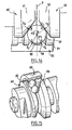
- the linear actuator comprises an inner tube 10 and an outer tube 20 whose diameter is greater than the diameter of the inner tube 10.
- the inner tube 10 extends partly in the outer tube.
- the two tubes 10 and 20 are locked in rotation relative to each other and are able to be driven to slide relative to each other in their longitudinal direction.
- the actuator comprises a drive mechanism comprising a drive shaft 30 extending along the longitudinal axis of the tubes 10 and 20.
- the shaft 30 is rotated by an electric motor 2 fixed to the one of its ends and positioned in the inner tube 10.
- the motor 2 and the shaft 30 are held in the inner tube 10 via a cylindrical support 3 fixed to the inner tube.
- the shaft 30 is guided in the inner tube 10 via two ball bearings 7 and 9 whose inner ring is mounted on the shaft 30 and the outer ring rests on the inner surface 11 of the inner tube 10.
- the two bearings 7 and 9 are held at a distance by a spacer 8 in the form of a cylindrical sleeve bearing on the inner rings of the bearings 7 and 9 and by means of a spacer 12 pinned in the inner tube 10 and bearing on the outer rings of the bearings 7 and 9.
- the recovery of the axial forces exerted on the bearings can be done either via the spacer 12, or by any other equivalent means (for example). example circlips blocking the bearing).
- the shaft 30 further supports an adjusting nut 4, a set of Belleville washers 5, a first clamping washer 6 positioned between the support 3 of the motor and the bearing 7.
- the clamping washer 6 bears on the inner cage of the 7.
- the shaft 30 also supports a second clamping washer 1 and a ball nut 70, positioned between the bearing 9 and a stop element 31 at the end of the shaft 30.
- the nut 70 consists of a succession of cams 40, 50 and 60 of generally cylindrical shapes mounted aligned on the shaft 30 and locked in rotation relative to the shaft by a key.
- the cams 40, 50, 60 have helical chamfers 41, 51 and 52, 62, oriented at 45 ° with respect to the axis of the shaft 30. These chamfers 41, 51, 52, 62 form two by two paths
- the balls 22 are in contact on the one hand with two opposite chamfer surfaces, 41 and 51, or 52 and 62 and on the other hand with the smooth inner surface 21 of the outer tube. 20.
- the radial force applied to the balls 22 is adjusted by tightening the nut 4.
- the adjusting nut 4 applies a compressive force on the Belleville washers 5 in the longitudinal direction of the shaft 30. This effort of compression is transmitted to the cams 40, 50, 60 via the clamping washer 6 which transmits and distributes the clamping force on the internal raceways of the bearings 7 and 9 and on the clamping washer 1.
- the cams 40, 50 , 60 are therefore in compression between the clamping washer 1, the balls 22 and the stop element 31 at the end of the shaft 30.
- the actuator of the figure 1 comprises two raceways formed by three cams 40, 50 and 60 aligned on the shaft 30.
- the force that can be provided by the actuator of the figure 1 depends directly on the preload applied to the balls and adjusted by the adjusting nut 4.
- the prestressing force that can be applied to the balls 22 remains limited by the Hertz pressure that may be experienced by the surface of the cams 40, 50, 60 and the inner surface 21 of the outer tube 20.
- the motor 2 of the actuator of the figure 1 When the motor 2 of the actuator of the figure 1 is in operation, it rotates the shaft 30 and therefore the cams 40, 50 and 60 which are keyed thereon. The balls 22 then roll between their raceway and the inner surface of the outer tube.
- the tangential velocity of the center of each ball 22 thus has two components: a tangential component perpendicular to the axis of rotation of the shaft 30 and a longitudinal component parallel to the axis of the shaft 30 due to the pitch of the propeller of the raceway.
- a ball 22 rotates about an axis inclined relative to the axis of the shaft 30 by an angle equivalent to that of the propeller of the raceway.
- the point of contact I between the ball 22 and the inner surface of the tube is always positioned perpendicular to the axis of rotation passing through the point O.
- the outer tube 20 is driven in translation to a speed proportional to the speed of rotation of the drive shaft 30 and the pitch of the helical path.
- the figure 3 represents an example of a cam 40 used in mounting the figure 1 .
- the cam 40 has a generally cylindrical shape. It comprises a central bore 43 intended to receive the drive shaft 30, as well as a keyway 44 formed from the bore 43 and intended to allow indexing of the cam 40 on the shaft 30.
- a helical chamfer 41 has been made by milling a circular edge of the cam 40.
- This cam is formed from a cylindrical piece of cross-section, one of whose circular edges is chamfered to form said inclined helical cam surface. relative to the axis of the cylindrical part, the ends of the helical surface joining with a recess surface of generally conical shape
- the milling operation is carried out using a conical cutter 100 whose cutting edges form an angle of 45 degrees relative to its axis of rotation 101.
- the cutter is mounted on a rotating machining spindle 102.
- a cylindrical piece 400 of revolution (shown in dashed lines) for forming the cam 40 is mounted on a turntable. It is arranged relative to the cutter 100 so that their axes 101 and 401 are parallel and have a spacing e given.
- the part 400 is animated during the milling operation of a rotational movement relative to its axis 401 (as indicated by the arrow R). Simultaneously, the cutter 100 is driven in a translation movement (indicated by the arrow T) along its axis 101.
- the translational movement is effected in a direction in which the cutter 100 moves away from the cylindrical part 400.
- piece 400 rotates 360 degrees while pin 102 is translated by a distance equal to the pitch of the helical chamfer to generate.
- This milling operation leads to the generation of the helical chamfer 41 oriented at 45 degrees with respect to the axis 401.
- the helical chamfer of the cam 40 forms a circumferential surface 41 which widens when it is traversed in the opposite direction to the milling and is connected at its ends by a recess of conical shape 45.
- This recess of conical shape is generated by the shape of the conical bur when taking the initial radial pass in the piece 400.
- the shape of the recess may vary depending on the initial setting path of the strawberry. If the conical cutter enters the workpiece 400 in a tangential pass, the recess obtained will be generally planar. If the conical cutter enters the workpiece 400 according to a skew grip, the recess obtained will be of generally planar shape with conical connection.
- the helical running surface must be obtained by a different method.
- a preliminary step of milling the cylindrical part with the aid of a cylindrical cutter in order first to obtain a helical surface oriented perpendicularly to the axis of the part.
- a step of milling the edge of the helical surface is carried out using a conical bur to make a helical chamfer oriented at 45 degrees with respect to the axis of the workpiece.
- the helical chamfer thus obtained forms a circumferential surface of constant width which is connected at its ends by a conical recess.
- the figure 5 represents the positioning of two cams 40 and 50 relative to one another on the drive shaft 30.
- the two cams 40 and 50 each have a surface 41, 51 of identical chamfer. They are positioned side-by-side on the drive shaft 30, so that their respective chamfer surfaces 41 and 51 face each other to form a helical raceway for the balls 22.
- the cams 40 and 50 are each The keyways 44 and 54 are positioned relative to the bore of the cams 40 and 50 so that the tapered recess surfaces 45 and 55 of the cams 40 are indexed to the shaft 30 by their keyway 44 or 54. and 50 are oppositely positioned opposite each other when they are mounted on the shaft 30.
- the tapered recess surfaces 45 and 55 of the two cams 40 and 50 advantageously form an enlarged zone 81 which accommodates the balls 22 and allows their recirculation.
- the shaft 30 of the actuator is rotated, the balls 22 roll on the race formed by the chamfer surfaces 41 and 51.
- a ball 22 reaches the recirculation zone 81 where both chamfer surfaces 41 and 51 have a maximum width, it is no longer in contact with the inner surface 21 of the outer tube 20 so that it no longer rolls.
- the ball 22 remains in the recirculation zone until it is pushed by the arrival of a next ball and thus automatically reengaged in the raceway.
- the nut 70 formed by the combination of cams 40, 50, 60 has the advantage of not requiring the formation of an internal recirculation path.
- the balls 22 are automatically "recycled” as soon as they reach the recirculation zone 81 joining the ends of a raceway.
- the figure 6 illustrates the positioning of the cams 40, 50 and 60 successive relative to each other on the drive shaft 30. These cams are arranged so that the recirculation zones of the balls are not aligned. More specifically, the cams are oriented on the drive shaft 30 so that the recirculation zones are distributed angularly in a regular manner about the axis of the shaft 30 (axis of rotation and translation of the actuator). So, on the figure 6 , the nut comprising two tracks respectively formed by the cams 40, 50 and 50, 60, it has two recirculation zones which are arranged at 180 degrees relative to each other about the axis of the tree 30.
- the cams In the case of a nut comprising three raceways which would have three recirculation zones, the cams would be oriented so that the recirculation zones are arranged at 120 degrees from each other about the axis of the cam. tree 30.
- the cams In general, in the case of a nut comprising N raceways (formed by N pairs of cams), the cams would be oriented so that the recirculation zones are arranged at 360 / N degrees relative to each other. others around the axis of the tree 30.
- This feature makes it possible to avoid nutation movement of the inner tube 10 with respect to the outer tube 20, which can occur when the actuator comprises only one pair of cams (that is to say a single raceway) or when the recirculation zones are arranged aligned.
- the inner and outer tubes 10 are formed of relatively light material: for example composite material or plastic or light alloy.
- raceways are formed on the inner surface 21 of the outer tube 20. These raceways make it possible to reduce the Hertz pressure exerted by the balls 22 on the surface of the tube 20.
- runways can be formed by roller burnishing of the inner surface 21 of the tube 20.
- the rolling tracks may advantageously be formed by the balls 22 themselves during the rotation of the shaft 30.
- the balls 22 produce a plastic deformation of the surface 21 forming tracks of rolling.
- raceways makes it possible to apply compression forces that would not be able to withstand a smooth cylindrical surface.
- these tracks make it possible to increase in an apparent manner the coefficient of friction ball / outer tube.
- raceways make it possible not to apply excessive prestressing force on the balls.
- the balls being guided by the rolling tracks they can not slide relative to the outer tubular body 20.
- These rolling tracks have a helical pitch substantially equal to the helical pitch of the raceway formed in the nut 70.
- the actuator comprises in combination rolling tracks on the inner surface 21 of the outer tube 20 and a nut 70 having recirculation zones in the form of enlarged spaces.
- the inner and outer tubes 20 are also formed of relatively light material.
- Running tracks are formed on the inner surface of the outer tube 20.
- the rolling tracks are constituted by a high-strength steel wire 91 positioned helically inside the outer tube 20.
- the balls 22 roll in support on two successive turns of the wire 91.
- This variant allows to obtain a connection between the balls 22 and the tracks of the tube 20 mechanically positive (there is more friction but support).
- the longitudinal components of the bearing forces on the turns of the wire 91 are positive supports.
- the inner surface 21 of the outer tube 20 comprises a helical groove 24 for receiving the steel wire 91.
- This variant makes it possible to use aluminum, KEVLAR ⁇ , carbon fiber or molded plastic tubes, which guarantees the lightness of the final actuator structure obtained.
- the inner surface 21 of the outer tube 20 is smooth.
- Running tracks are formed on the inner surface of the outer tube 20. They are constituted by a first high-strength steel wire 91 positioned helically inside the outer tube 20 and on which the balls 22 abut.
- a second intermediate wire 92 having a diameter smaller than that of the first wire 91 extends between the turns of the first wire. This second wire 92 maintains the spacing between the turns of the first wire. It avoids in particular that the turns of the first wire 91 do not deviate during the passage of a ball 22.
- the balls 22 are not in contact with the intermediate wire 92.
- This implementation is particularly simple and avoids resorting to machining techniques of the outer tube 20.
- the figure 10 represents another variant of the invention in which rolling tracks are made by plastic deformation in a calibrated inner tube.
- the inner tube 93 is disposed in the outer tube 20 and welded thereto.
- the raceways in the inner tube 93 are made in the following manner.
- a roller or forming machine which comprises a roller holder provided with three rollers arranged at 120 degrees with respect to each other and oriented according to the helix angle of the track to be obtained.
- the inner tube 93 is fixed on a mandrel of shape close to the inner profile to be obtained.
- the roller holder is rotated.
- the tube 93 and the mandrel are driven in translation.
- the translational speed of the tube 93 is adjusted so that the translation distance is equal to the pitch of the helix at each turn of the roller holder.
- the operation can be done in one go and the tube 93 is then strongly hardened which makes the rigidity and the hardness of the running surface greater.
- the tube 93 is introduced into the outer tube 20.
- the figure 11 represents a welding step of the inner tube 93 in which the raceways are formed in the outer tube 20 of the actuator.
- a spot welder comprising an inner wheel 201 mounted on a shaft 203 and an outer motorized wheel 202.
- the inner wheel is inclined relative to the shaft 203 by an angle equal to the helix angle of the raceways.
- the welds are made at the bottom of the helical tracks in contact with the outer tube 20.
- the assembly thus formed is boxed and the axial deformation of the assembly is negligible. This small deformation guarantees a linearity of the transformation of the rotational movement into translation movement in the final actuator.
- each cam 40, 50 or 60 has a chamfer oriented at an angle less than or equal to 45 degrees with respect to the axis 401 of the cam, preferentially strictly less than 45 degrees and preferably about 35 degrees.
- This characteristic makes it possible to reduce the radial force which acts as a reaction support for the forces applied to the raceway.
- this feature facilitates the passage of balls over the edges of the tracks during their re-circulation. Indeed, the component of the force that allows the passage of a ball over a runway edge (formed for example by a wire) passes over the edge of the track.
- the figure 12 represents a linear actuator telescopic type. This actuator is similar to that of the figure 1 . It comprises an inner tube 10 and an outer tube 20 whose diameter is greater than the diameter of the inner tube 10. The inner tube 10 extends in part in the outer tube 20. It also comprises a nut 70 consisting of a succession of cams 40, 50 and 60 of cylindrical general shapes.
- the linear actuator shown on the figure 12 further comprises a third tube 300 whose diameter is greater than that of the outer tube 20.
- the outer tube extends partly into the third tube 300.
- the nut 370 is rigidly connected to the outer tube 20 so that the outer tube 20 is adapted to drive in rotation a nut 370 comprising cams 340 and 350.
- the tubes 10 and 300 are locked in rotation relative to each other and are able to be driven to slide relative to each other in their longitudinal direction.
- the outer tube 20 is mounted floating, that is to say that it is blocked in rotation neither with the inner tube 10 nor with the third tube 300.
- the motor 2 of the actuator of the figure 12 When the motor 2 of the actuator of the figure 12 is in operation, it rotates the nut 70 comprising the cams 40, 50 and 60. The balls 22 then roll between their raceway and the inner surface of the intermediate tube 20. The tubes 10 and 300 being locked in rotation l relative to each other, the rotation of the nut 70 causes the translation of the inner tube 10 relative to the outer tube assembly 20 and third tube 300. This translation is limited by a stop.
- the tubes 10 and 20 are then rotated simultaneously.
- the outer tube 20 then rotates the nut 370 comprising cams 340 and 350.
- the balls 22 then roll between their race formed by the cams 340 and 350 and the inner surface of the third tube 300.
- the tubes 10 and 300 being locked in rotation relative to each other, the rotation of the nut 370 causes the translation of the inner tube 10 and outer tube 20 relative to the third tube 300.
- the telescopic actuator thus produced deploys in two stages.
- the inner tube 10 is translated relative to the outer tube 20 and the third tube 300
- the inner and outer tubes 20 and 20 are translated relative to the third tube 300.
- This deployment in two stages is due to the fact that the torque necessary to drive the nut 370 in rotation relative to the third tube is greater than the torque necessary to drive the nut 70 in rotation with respect to the outer tube.
- the deployment can also be done randomly depending on the friction couples appearing in the mechanism.
- Such a telescopic actuator has the advantage of being able to reach greater deployment lengths than with a simple actuator as represented on the figure 1 .
- the nut 70 comprises two pairs of cams and the nut 370 comprises a single pair of cams.
- the figure 13 represents the actuator of the figure 12 in the deployed position.
- the tubes 20 and 300 each have on their inner surfaces running tracks. These tracks preferably have the same pitch. Thus, the deployment of the actuator will be at constant speed. In addition, it will be possible by counting the number of engine revolutions to know the exact position of the actuator.
- the deployment speed of the actuator will vary depending on the tube that will be moving at a given moment.
- a telescopic actuator comprising a plurality of tubes adapted to be driven in translation relative to one another, it is possible to choose to set different steps of tracks for the different tubes.
- the figure 14 represents a ball 22 of center O held between the chamfer surfaces 41 and 51 cams 40 and 50 and a raceway formed for example by two wires 92 and 94.
- the contact points between the ball 22 and the cam 40, the cam 50, the wire 92 and the wire 94 are respectively referenced B, D, C and A.
- the angle between the plane P of the right section of the actuator passing through O and the line (OA) is noted ⁇ 1 and the angle between the plane P and the line (OB) is denoted ⁇ 2 .
- the forces exerted on the ball by the cams and the raceway are denoted F A , F B , F C and F D.
- the cams 40 and 50 are rotated so that the ball 22 reaches an enlarged recirculation zone as illustrated in FIG. figure 15 . From this moment, the ball 22 is no longer in contact with the cam 50 so that it is no longer in equilibrium because no force is applied in D. The ball 22 is subjected to a force giving it an acceleration enabling it to disengage from the raceway and to cross the wire 94 to position itself on the adjacent track.
- the passage of the ball 22 from one track to the other can be realized only if ⁇ 1 ⁇ 2 so that the resultant of the efforts on the ball passes over the wire 94.
- ⁇ 2 can be chosen between 50 and 60 degrees, preferably 55 degrees.
- the cam 40 has a surface 41 of helical chamfer oriented at 35 degrees with respect to the plane P.
- a cam having such a helical chamfer can be obtained by machining a cylindrical part with a conical cutter having a half-angle at the apex of 55 degrees.
- the figure 16 represents the positioning of two cams 40 and 50 relative to each other.
- the plane Q extends transversely to the plane of the diagram and passes through the axis of rotation of the nut 70 including the two cams 40 and 50.
- the cams 40 and 50 are identical. They are arranged opposite each other so that the rolling surfaces 41 and 51 face each other.
- the cams are indexed by their keyways (see figure 5 ), the keyways extending in the plane Q.
- the keyways are positioned to form an angle ⁇ relative to the mark consisting of an end of the helical surface corresponding to the plane of attack of the cutter.
- the angle ⁇ can be adjusted in order to minimize the space of evolution of the balls in the recirculation zone 81 to avoid the presence of several balls simultaneously in this zone and to keep the greatest possible number of "working" balls ".
- the adjustment of the angle ⁇ depends in particular on the pitch of the raceway, the orientation of the cam surfaces 41 and 51, the diameter of the balls 22, the diameter of the son 92 and 94 used for the realization of the tracks.
- This angle ⁇ is to determine the volumes in which the center O of a ball moves when it is respectively resting on one of the cam surfaces, resting on the other cam surface and in bearing on the rolling tracks. The intersection of these volumes represents the space in which the ball is guided. This space can be modified by varying the angle ⁇ . The intersection space must be both wide enough for a ball to enter the re-circulation zone and move in the helical raceway and sufficiently restricted to prevent multiple balls from being simultaneously in the area. The shape of the space obtained depends on the angle ⁇ and also on the shape of the recess surfaces of the cams.
Landscapes
- Engineering & Computer Science (AREA)
- General Engineering & Computer Science (AREA)
- Mechanical Engineering (AREA)
- Transmission Devices (AREA)
Claims (16)
- Aktuator, umfassend einen ersten röhrenförmigen Körper (20), Antriebsmittel (2), die einen Motor umfassen und dazu bestimmt sind, eine Schraubenmutter (70) anzutreiben, die innerhalb des röhrenförmigen Körpers (20) angeordnet ist, und wenigstens eine Rollbahn (41-51 ; 52-62) aufweist, die einen wendelförmigen Teil umfaßt, der sich um die Schraubenmutter (70) herum nach einem Winkel, der kleiner als 360° ist, erstreckt, und einen erweiterten Teil (81), der die Enden des wendelförmigen Stücks verbindet, wobei die besagte erweiterte Zone (81) eine Zone zum erneuten Umlauf der Kugeln (22) bildet, die zwischen der Rollbahn (41-51 ; 52-62) und der inneren Oberfläche (21) angeordnet sind, entsprechend diesem ersten röhrenförmigen Körper (20) und umfassend wendelförmige Rollspuren für die Führung der Kugeln (22), wobei der Motor fest innerhalb eines zweiten Körpers (10), der geeignet ist, bezüglich des ersten röhrenförmigen Körpers (20) in Translationsbewegung angetrieben zu werden, montiert ist, und die Schraubenmutter (70) mehrere ausgerichtete Elemente (40, 50, 60) mit zylindrischer Allgemeinform umfaßt, die jeweils wenigstens eine Abschrägung (41-51 ; 52-62), die eine wendelförmige Nockenoberfläche bildet, aufweisen, wobei die Abschrägungen (41-51 ; 52-62) paarweise wendelförmige Rollbahnen bilden, in denen die Kugeln (22) positioniert sind.
- Aktuator nach Anspruch 1, dadurch gekennzeichnet, daß die Rollspuren auf der inneren Oberfläche (21) des ersten röhrenförmigen Körpers (20) einen wendelförmigen Schritt aufweisen, der im wesentlichen dem wendelförmigen Schritt einer Rollbahn (41-51; 52-62) der Schraubenmutter (70) entspricht.
- Aktuator nach irgendeinem der vorgehenden Ansprüche, dadurch gekennzeichnet, daß die Schraubenmutter (70) mehrere Rollbahnen (41-51 ; 52-62) umfaßt, wobei jeder der Bahnen eine Zone zum erneuten Umlauf der Kugeln aufweist, und daß die Rollbahnen derart angeordnet sind, daß die Umlaufzonen der Kugeln nicht nach einer Translationsbewegungsrichtung des Aktuators ausgerichtet sind.
- Aktuator nach Anspruch 3, dadurch gekennzeichnet, daß die Rollbahnen (41-51 ; 52-62) derart angeordnet sind, so daß die Zonen zum erneuten Umlauf winklig um die Translationsbewegungsrichtung des Aktuators herum regelmäßig verteilt sind.
- Aktuator nach irgendeinem der vorgehenden Ansprüche, dadurch gekennzeichnet, daß jede wendelförmige Nockenoberfläche (41, 51, 52, 62) einen Absatz (45, 55) bildet, und daß zwei Elemente (40, 50, 60) hinsichtlich einander so positioniert sind, daß ihre Absätze (45, 55) gegenüberliegend sind, wobei die besagten Absätze die Zone zum erneuten Umlauf (81) der Kugeln (22) bilden.
- Aktuator nach irgendeinem der vorgehenden Ansprüche, dadurch gekennzeichnet, daß der auf die Kugeln (22) ausgeübte Vordruck durch das Festklemmen der Elemente (40, 50, 60) untereinander verursacht ist.
- Aktuator nach Anspruch 6, dadurch gekennzeichnet, daß er eine Schraubenmutter zum Einstellen (4) der Elemente (40, 50, 60) umfaßt, um den auf die Kugeln ausgeübten Vordruck (22) zu regeln.
- Aktuator nach Anspruch 7, dadurch gekennzeichnet, daß er elastische Mittel (5) umfaßt, die zwischen der Einstellmutter (4) und den Elementen (40, 50, 60) der Schraubenmutter (70) angeordnet sind, mit deren Hilfe die Einstellmutter (4) einen Vordruck auf die Elemente (40, 50, 60) ausübt.
- Aktuator nach irgendeinem der vorgehenden Ansprüche, dadurch gekennzeichnet, daß jedes Element (40, 50, 60) ab einem zylindrischen Stück mit geradem Querschnitt (400) gebildet ist, von dem die eine von den Kreiskanten abgeschrägt ist, um die besagte wendelförmige Nockenoberfläche zu bilden, die hinsichtlich der Achse (401) des zylindrischen Stückes (400) geneigt ist, wobei die Enden der wendelförmigen Oberfläche sich über eine Oberfläche des Absatzes (45) mit konischer Allgemeinform verbinden.
- Aktuator nach Anspruch 9, dadurch gekennzeichnet, daß die Rollbahn (41-51 ; 52-62) eine erweiterte Zone (81) zum erneuten Umlauf der Kugeln (22) umfaßt, die durch die Absatzoberflächen von zwei Elementen (40, 50) gebildet ist, wobei die Absatzoberflächen gegenüberliegend entgegengesetzt befindlich seien.
- Aktuator nach irgendeinem der Ansprüche 1 bis 10, dadurch gekennzeichnet, daß die Rollspuren im Bereich der inneren Oberfläche (21) des röhrenförmigen Körpers (20) durch plastische Verformung dieser inneren Oberfläche (21) durch die Kugeln (22) gebildet sind, gefolgt von einer Behandlung, vorgesehen, um diese innere Oberfläche (21) des röhrenförmigen Körpers (20) zu härten.
- Aktuator nach irgendeinem der Ansprüche 1 bis 10, dadurch gekennzeichnet, daß die Rollbahnen im Bereich der inneren Oberfläche (21) des ersten röhrenförmigen Körpers (20) durch wenigstens einen Draht (91) gebildet sind, der schraubenförmig innerhalb des ersten röhrenförmigen Körpers (20) angeordnet ist.
- Aktuator nach Anspruch 12, dadurch gekennzeichnet, daß er einen ersten Draht (91), der schraubenförmig innerhalb des ersten röhrenförmigen Körpers (20) angeordnet ist, auf welchem die Kugeln (22) abstützen, und einen zweiten dazwischen liegenden Draht (92), der einen kleineren Durchmesser aufweist als jenen des ersten Drahts (91) und der sich zwischen den Windungen des ersten Drahts (91) erstreckt, umfaßt, wobei dieser zweite Draht (92) den Abstand zwischen den Windungen des ersten Drahts (91) beibehält.
- Aktuator nach irgendeinem der Ansprüche 1 bis 10, dadurch gekennzeichnet, daß er ein inneres Rohr (93) umfaßt, das im röhrenförmigen Körper (20) angeordnet ist und an diesem letzteren geschweißt ist, wobei das innere Rohr (93) die durch Walzenpolieren ausgeführten Rollspuren aufweist.
- Aktuator nach irgendeinem der vorgehenden Ansprüche, dadurch gekennzeichnet, daß er einen dritten röhrenförmigen Körper (300) aufweist, wobei der erste röhrenförmige Körper (20) mit einer zweiten Schraubenmutter (370) verbunden sei, wobei die Drehung der zweiten Schraubenmutter (370) die Translationsbewegung des dritten Körpers hinsichtlich des ersten röhrenförmigen Körpers (20) bewirkt, wobei der Aktuator also einen Aktuator der Art teleskopisch darstellt.
- Aktuator nach irgendeinem der vorgehenden Ansprüche, dadurch gekennzeichnet, daß der erste röhrenförmige Körper (20) aus Aluminium, KEVLAR®, Kohlefasern oder geformten Kunststoff gebildet ist.
Priority Applications (1)
| Application Number | Priority Date | Filing Date | Title |
|---|---|---|---|
| DE60303610T DE60303610T3 (de) | 2002-08-29 | 2003-08-29 | Schraubenförmige linearantriebseinrichtung mit nocken |
Applications Claiming Priority (3)
| Application Number | Priority Date | Filing Date | Title |
|---|---|---|---|
| FR0210715 | 2002-08-29 | ||
| FR0210715A FR2844019A1 (fr) | 2002-08-29 | 2002-08-29 | Actionneur mecanique a friction comprenant un ecrou interne a billes dans lequel les billes sont montees avec precontrai nte |
| PCT/FR2003/002607 WO2004020871A2 (fr) | 2002-08-29 | 2003-08-29 | Actionneur mecanique incluant un ecrou a cames helicoidales |
Publications (4)
| Publication Number | Publication Date |
|---|---|
| EP1523630A2 EP1523630A2 (de) | 2005-04-20 |
| EP1523630B1 EP1523630B1 (de) | 2006-02-15 |
| EP1523630B8 EP1523630B8 (de) | 2006-06-28 |
| EP1523630B2 true EP1523630B2 (de) | 2011-08-10 |
Family
ID=31502977
Family Applications (1)
| Application Number | Title | Priority Date | Filing Date |
|---|---|---|---|
| EP03769538A Expired - Lifetime EP1523630B2 (de) | 2002-08-29 | 2003-08-29 | Schraubenförmige linearantriebseinrichtung mit nocken |
Country Status (7)
| Country | Link |
|---|---|
| US (1) | US20050268736A1 (de) |
| EP (1) | EP1523630B2 (de) |
| AU (1) | AU2003278225A1 (de) |
| DE (1) | DE60303610T3 (de) |
| ES (1) | ES2258734T5 (de) |
| FR (1) | FR2844019A1 (de) |
| WO (1) | WO2004020871A2 (de) |
Families Citing this family (16)
| Publication number | Priority date | Publication date | Assignee | Title |
|---|---|---|---|---|
| FR2888277B1 (fr) * | 2005-07-08 | 2007-09-07 | Bubendorff Sa | Dispositif d'entrainement pour systeme de fermeture de batiment |
| DE202005020087U1 (de) * | 2005-12-07 | 2007-04-19 | BROSE SCHLIEßSYSTEME GMBH & CO. KG | Antriebsanordnung zur motorischen Verstellung einer Kraftfahrzeugtür o.dgl. |
| US8001861B2 (en) * | 2007-10-10 | 2011-08-23 | Parker-Hannifin Corporation | High force electro-mechanical actuator |
| JP2009168098A (ja) * | 2008-01-15 | 2009-07-30 | Jtekt Corp | ボールねじ装置 |
| FR2938893B1 (fr) * | 2008-11-25 | 2011-07-15 | Innovation Technologie Conseil Itc | Actionneur lineaire |
| DE102010000970C5 (de) * | 2010-01-18 | 2022-10-13 | Suspa Gmbh | Höhenverstellbare Betätigungs-Einrichtung |
| FR2959837B1 (fr) * | 2010-05-07 | 2012-05-04 | Eurocopter France | Systeme de commandes de vol simplifiees comportant un dispositif de friction debrayable |
| IT1399963B1 (it) * | 2010-05-17 | 2013-05-09 | Iacobucci Hf Electronics S P A | Compattatore di rifiuti |
| DE202010009334U1 (de) * | 2010-06-21 | 2011-09-22 | BROSE SCHLIEßSYSTEME GMBH & CO. KG | Spindelantrieb für die motorische Verstellung eines Verstellelements eines Kraftfahrzeugs |
| EP2834531B1 (de) * | 2012-04-03 | 2019-01-23 | Schaeffler Technologies AG & Co. KG | Betätigungsvorrichtung für eine kupplung |
| DE102013207210A1 (de) * | 2012-05-11 | 2013-11-14 | Schaeffler Technologies AG & Co. KG | Verfahren zum Betrieb einer Betätigungsvorrichtung für eine Kupplung und Betätigungsvorrichtung für eine Kupplung |
| US20140150580A1 (en) * | 2012-12-01 | 2014-06-05 | John McEntee | Rotary to linear transmission |
| DE102013016769A1 (de) * | 2013-10-09 | 2015-04-09 | Kuka Laboratories Gmbh | Instrumentenanordnung |
| EP3473319A1 (de) * | 2017-10-18 | 2019-04-24 | Metso Sweden Ab | Filterplattenanordnung und verfahren zum trennen der feststoffkomponenten von den flüssigen komponenten einer aufschlämmung |
| DE102017127937A1 (de) * | 2017-11-27 | 2019-05-29 | Logicdata Electronic & Software Entwicklungs Gmbh | Teleskopierbarer Linearaktuator und höhenverstellbarer Tisch |
| DE102022120145B4 (de) * | 2022-08-10 | 2024-06-06 | Schaeffler Technologies AG & Co. KG | Planetenwälzgewindetrieb |
Citations (7)
| Publication number | Priority date | Publication date | Assignee | Title |
|---|---|---|---|---|
| US3009367A (en) † | 1960-09-15 | 1961-11-21 | Lewis G Striggow | Ball nut cartridge |
| GB1117353A (en) † | 1965-04-30 | 1968-06-19 | Plessey Co Ltd | Improvements relating to ball-type screw and nut devices |
| US3572136A (en) † | 1969-03-17 | 1971-03-23 | Richard B Stanley | Linear actuator |
| DE3105494A1 (de) † | 1980-07-28 | 1982-10-14 | Anton 7326 Heinigen Koukal | Kugelumlauf-spindel-antriebsvorrichtung |
| US4366723A (en) † | 1979-10-13 | 1983-01-04 | Richard Wilke | Recirculating-ball drive |
| JPH08198595A (ja) † | 1995-01-30 | 1996-08-06 | Hitachi Ltd | スクリュー式ジャッキ |
| US6393930B1 (en) † | 1999-04-29 | 2002-05-28 | Korea Advanced Institute Science And Technology | Ball screw with inner ball circulation and linear actuator equipped with the ball screw |
Family Cites Families (11)
| Publication number | Priority date | Publication date | Assignee | Title |
|---|---|---|---|---|
| US2299785A (en) * | 1940-05-16 | 1942-10-27 | Barrett Engineering Company | Radio antenna |
| US2756609A (en) * | 1954-03-26 | 1956-07-31 | Cleveland Pneumatic Tool Co | Ball friction drive |
| US2936646A (en) * | 1956-01-11 | 1960-05-17 | Keystone Plastics Inc | Mechanical assembly |
| FR2328138A1 (fr) * | 1975-10-14 | 1977-05-13 | Verdun Georges | Dispositif de transformation d'un mouvement de rotation en un mouvement de translation a cheminement ferme de billes |
| IT1072019B (it) * | 1976-11-19 | 1985-04-10 | Roltra Spa | Accoppiamento di trasmissione a vite madrevite a circolazione di sfere |
| US5358265A (en) * | 1990-08-13 | 1994-10-25 | Yaple Winfred E | Motorcycle lift stand and actuator |
| US5636549A (en) * | 1993-12-22 | 1997-06-10 | Hughes Electronics | Wire wound threaded elements including lead screws, roller not assemblies and process |
| US5943910A (en) * | 1996-10-04 | 1999-08-31 | Thomson Saginaw Ball Screw Company, L.L.C. | Telescopic ball nut and screw linear actuator and method of constucting and using it |
| US6101889A (en) * | 1998-01-20 | 2000-08-15 | Thomson Saginaw Ball Screw Company, Llc | Ball screw and nut linear actuator assemblies and methods of constructing and operating them |
| US20040093973A1 (en) * | 2000-10-23 | 2004-05-20 | Georg Halasy-Wimmer | Ball screw |
| DE10128252A1 (de) * | 2000-10-23 | 2002-04-25 | Continental Teves Ag & Co Ohg | Gewindetrieb |
-
2002
- 2002-08-29 FR FR0210715A patent/FR2844019A1/fr not_active Withdrawn
-
2003
- 2003-08-29 AU AU2003278225A patent/AU2003278225A1/en not_active Abandoned
- 2003-08-29 ES ES03769538T patent/ES2258734T5/es not_active Expired - Lifetime
- 2003-08-29 DE DE60303610T patent/DE60303610T3/de not_active Expired - Lifetime
- 2003-08-29 WO PCT/FR2003/002607 patent/WO2004020871A2/fr not_active Ceased
- 2003-08-29 US US10/524,298 patent/US20050268736A1/en not_active Abandoned
- 2003-08-29 EP EP03769538A patent/EP1523630B2/de not_active Expired - Lifetime
Patent Citations (7)
| Publication number | Priority date | Publication date | Assignee | Title |
|---|---|---|---|---|
| US3009367A (en) † | 1960-09-15 | 1961-11-21 | Lewis G Striggow | Ball nut cartridge |
| GB1117353A (en) † | 1965-04-30 | 1968-06-19 | Plessey Co Ltd | Improvements relating to ball-type screw and nut devices |
| US3572136A (en) † | 1969-03-17 | 1971-03-23 | Richard B Stanley | Linear actuator |
| US4366723A (en) † | 1979-10-13 | 1983-01-04 | Richard Wilke | Recirculating-ball drive |
| DE3105494A1 (de) † | 1980-07-28 | 1982-10-14 | Anton 7326 Heinigen Koukal | Kugelumlauf-spindel-antriebsvorrichtung |
| JPH08198595A (ja) † | 1995-01-30 | 1996-08-06 | Hitachi Ltd | スクリュー式ジャッキ |
| US6393930B1 (en) † | 1999-04-29 | 2002-05-28 | Korea Advanced Institute Science And Technology | Ball screw with inner ball circulation and linear actuator equipped with the ball screw |
Also Published As
| Publication number | Publication date |
|---|---|
| DE60303610T3 (de) | 2012-01-26 |
| WO2004020871A3 (fr) | 2004-07-01 |
| DE60303610D1 (de) | 2006-04-20 |
| EP1523630B8 (de) | 2006-06-28 |
| DE60303610T2 (de) | 2006-10-19 |
| FR2844019A1 (fr) | 2004-03-05 |
| EP1523630B1 (de) | 2006-02-15 |
| US20050268736A1 (en) | 2005-12-08 |
| AU2003278225A1 (en) | 2004-03-19 |
| EP1523630A2 (de) | 2005-04-20 |
| ES2258734T3 (es) | 2006-09-01 |
| ES2258734T5 (es) | 2012-01-02 |
| WO2004020871A2 (fr) | 2004-03-11 |
Similar Documents
| Publication | Publication Date | Title |
|---|---|---|
| EP1523630B2 (de) | Schraubenförmige linearantriebseinrichtung mit nocken | |
| FR2517783A1 (fr) | Convertisseur de mouvement rotatif en mouvement lineaire comportant des billes en roulement et mecanisme d'avance a deux vitesses contenant un tel convertisseur | |
| FR2522764A1 (fr) | Convertisseur de mouvement de rotation en mouvement lineaire a billes et mecanisme d'avance utilisant un tel convertisseur | |
| CH669244A5 (fr) | Vis a rouleaux satellites recircules. | |
| FR2680841A1 (fr) | Joint a rainures transversales, a vitesse constante et ayant un centre fixe. | |
| FR3028714A1 (fr) | Mecanisme de vis et ecrou a billes. | |
| FR2671151A1 (fr) | Joint homocinetique muni de surfaces d'appui sur la cage de dimensions reduites. | |
| FR2521666A1 (fr) | Accouplement cannele a coulissement illimite | |
| FR3143078A1 (fr) | Dispositif de transmission de couple, dispositif d’assistance électrique et cycle associé | |
| CA3174649A1 (fr) | High-speed spindle with forced mechanical vibratory assistance | |
| FR2891499A1 (fr) | Agencement de joint articule. | |
| EP0165083B1 (de) | Verfahren zur Wiederherstellung von Labyrinthdichtungen, insbesondere für Turbomaschinen und Werkzeuge dafür | |
| FR2643839A1 (fr) | Procede et machine pour former des nervures de renforcement interne dans un tube ou tuyau d'echangeur de chaleur | |
| EP0015243B1 (de) | Kugelführungsvorrichtung für Längs- und Drehbewegungen | |
| EP0013259A1 (de) | Längs- und/oder drehbewegliches Führungselement | |
| WO2022128449A1 (fr) | Corps de stator pour machine electrique a flux axial et procede de fabrication d'un tel corps de stator | |
| FR2632037A1 (fr) | Transmission a variation continue a courroie plate | |
| FR2859005A1 (fr) | Dispositif a vis et a billes a course limitee | |
| WO2018167021A1 (fr) | Laminoir multimandrin, méthode de réglage de la position des mandrins d'un tel laminoir et procédé de laminage en continu au moyen d'un tel laminoir | |
| FR2687945A1 (fr) | Procede et dispositif de tournage par generation. | |
| EP4055300B1 (de) | Rollenlaufwerkselement | |
| FR3103444A1 (fr) | Système de réglage d’un effort résistant s’opposant à un mouvement relatif de translation entre deux éléments télescopiques | |
| FR2714689A1 (fr) | Dispositif de crantage de surfaces extérieures de produits en béton. | |
| EP1510284A1 (de) | Welle mit einer optischen Codering und Verfahren zu deren Herstellung | |
| FR2473930A2 (fr) | Outillage pour la reparation, en particulier pour rodage d'un siege de robinet |
Legal Events
| Date | Code | Title | Description |
|---|---|---|---|
| PUAI | Public reference made under article 153(3) epc to a published international application that has entered the european phase |
Free format text: ORIGINAL CODE: 0009012 |
|
| 17P | Request for examination filed |
Effective date: 20050201 |
|
| AK | Designated contracting states |
Kind code of ref document: A2 Designated state(s): AT BE BG CH CY CZ DE DK EE ES FI FR GB GR HU IE IT LI LU MC NL PT RO SE SI SK TR |
|
| AX | Request for extension of the european patent |
Extension state: AL LT LV MK |
|
| 17Q | First examination report despatched |
Effective date: 20050615 |
|
| GRAP | Despatch of communication of intention to grant a patent |
Free format text: ORIGINAL CODE: EPIDOSNIGR1 |
|
| GRAS | Grant fee paid |
Free format text: ORIGINAL CODE: EPIDOSNIGR3 |
|
| DAX | Request for extension of the european patent (deleted) | ||
| RBV | Designated contracting states (corrected) |
Designated state(s): DE ES FR GB IT |
|
| GRAA | (expected) grant |
Free format text: ORIGINAL CODE: 0009210 |
|
| AK | Designated contracting states |
Kind code of ref document: B1 Designated state(s): DE ES FR GB IT |
|
| REG | Reference to a national code |
Ref country code: GB Ref legal event code: FG4D Free format text: NOT ENGLISH |
|
| RAP2 | Party data changed (patent owner data changed or rights of a patent transferred) |
Owner name: INNOVATION TECHNOLOGIE CONSEIL ITC Owner name: BUBENDORFF S.A. |
|
| REF | Corresponds to: |
Ref document number: 60303610 Country of ref document: DE Date of ref document: 20060420 Kind code of ref document: P |
|
| RAP2 | Party data changed (patent owner data changed or rights of a patent transferred) |
Owner name: BUBENDORFF SOCIETE ANONYME Owner name: INNOVATION TECHNOLOGIE CONSEIL ITC |
|
| GBT | Gb: translation of ep patent filed (gb section 77(6)(a)/1977) |
Effective date: 20060515 |
|
| REG | Reference to a national code |
Ref country code: ES Ref legal event code: FG2A Ref document number: 2258734 Country of ref document: ES Kind code of ref document: T3 |
|
| PLBI | Opposition filed |
Free format text: ORIGINAL CODE: 0009260 |
|
| PLAX | Notice of opposition and request to file observation + time limit sent |
Free format text: ORIGINAL CODE: EPIDOSNOBS2 |
|
| 26 | Opposition filed |
Opponent name: SOMFY Effective date: 20061115 |
|
| PLBB | Reply of patent proprietor to notice(s) of opposition received |
Free format text: ORIGINAL CODE: EPIDOSNOBS3 |
|
| APBM | Appeal reference recorded |
Free format text: ORIGINAL CODE: EPIDOSNREFNO |
|
| APBP | Date of receipt of notice of appeal recorded |
Free format text: ORIGINAL CODE: EPIDOSNNOA2O |
|
| PLAB | Opposition data, opponent's data or that of the opponent's representative modified |
Free format text: ORIGINAL CODE: 0009299OPPO |
|
| APAH | Appeal reference modified |
Free format text: ORIGINAL CODE: EPIDOSCREFNO |
|
| R26 | Opposition filed (corrected) |
Opponent name: SOMFY Effective date: 20061115 |
|
| APBQ | Date of receipt of statement of grounds of appeal recorded |
Free format text: ORIGINAL CODE: EPIDOSNNOA3O |
|
| APBU | Appeal procedure closed |
Free format text: ORIGINAL CODE: EPIDOSNNOA9O |
|
| PUAH | Patent maintained in amended form |
Free format text: ORIGINAL CODE: 0009272 |
|
| STAA | Information on the status of an ep patent application or granted ep patent |
Free format text: STATUS: PATENT MAINTAINED AS AMENDED |
|
| 27A | Patent maintained in amended form |
Effective date: 20110810 |
|
| AK | Designated contracting states |
Kind code of ref document: B2 Designated state(s): DE ES FR GB IT |
|
| REG | Reference to a national code |
Ref country code: DE Ref legal event code: R102 Ref document number: 60303610 Country of ref document: DE Effective date: 20110810 |
|
| REG | Reference to a national code |
Ref country code: GB Ref legal event code: 732E Free format text: REGISTERED BETWEEN 20111201 AND 20111207 |
|
| REG | Reference to a national code |
Ref country code: ES Ref legal event code: DC2A Ref document number: 2258734 Country of ref document: ES Kind code of ref document: T5 Effective date: 20120102 |
|
| REG | Reference to a national code |
Ref country code: DE Ref legal event code: R082 Ref document number: 60303610 Country of ref document: DE Representative=s name: PATENTANWAELTE UND RECHTSANWALT DR. WEISS, ARA, DE Ref country code: DE Ref legal event code: R082 Ref document number: 60303610 Country of ref document: DE Representative=s name: PATENTANWAELTE UND RECHTSANWALT WEISS, ARAT & , DE |
|
| REG | Reference to a national code |
Ref country code: FR Ref legal event code: PLFP Year of fee payment: 14 |
|
| REG | Reference to a national code |
Ref country code: FR Ref legal event code: PLFP Year of fee payment: 15 |
|
| REG | Reference to a national code |
Ref country code: FR Ref legal event code: PLFP Year of fee payment: 16 |
|
| PGFP | Annual fee paid to national office [announced via postgrant information from national office to epo] |
Ref country code: GB Payment date: 20220721 Year of fee payment: 20 |
|
| PGFP | Annual fee paid to national office [announced via postgrant information from national office to epo] |
Ref country code: FR Payment date: 20220725 Year of fee payment: 20 |
|
| PGFP | Annual fee paid to national office [announced via postgrant information from national office to epo] |
Ref country code: IT Payment date: 20220830 Year of fee payment: 20 Ref country code: ES Payment date: 20221027 Year of fee payment: 20 Ref country code: DE Payment date: 20221014 Year of fee payment: 20 |
|
| REG | Reference to a national code |
Ref country code: DE Ref legal event code: R071 Ref document number: 60303610 Country of ref document: DE |
|
| REG | Reference to a national code |
Ref country code: ES Ref legal event code: FD2A Effective date: 20230905 |
|
| REG | Reference to a national code |
Ref country code: GB Ref legal event code: PE20 Expiry date: 20230828 |
|
| PG25 | Lapsed in a contracting state [announced via postgrant information from national office to epo] |
Ref country code: GB Free format text: LAPSE BECAUSE OF EXPIRATION OF PROTECTION Effective date: 20230828 Ref country code: ES Free format text: LAPSE BECAUSE OF EXPIRATION OF PROTECTION Effective date: 20230830 |