EP1523630B2 - Mechanical actuator including a helical-cam nut - Google Patents
Mechanical actuator including a helical-cam nut Download PDFInfo
- Publication number
- EP1523630B2 EP1523630B2 EP03769538A EP03769538A EP1523630B2 EP 1523630 B2 EP1523630 B2 EP 1523630B2 EP 03769538 A EP03769538 A EP 03769538A EP 03769538 A EP03769538 A EP 03769538A EP 1523630 B2 EP1523630 B2 EP 1523630B2
- Authority
- EP
- European Patent Office
- Prior art keywords
- nut
- balls
- tubular body
- ball
- actuator
- Prior art date
- Legal status (The legal status is an assumption and is not a legal conclusion. Google has not performed a legal analysis and makes no representation as to the accuracy of the status listed.)
- Expired - Lifetime
Links
- 239000004033 plastic Substances 0.000 claims description 5
- 229910052799 carbon Inorganic materials 0.000 claims description 3
- 229920000271 Kevlar® Polymers 0.000 claims description 2
- XAGFODPZIPBFFR-UHFFFAOYSA-N aluminium Chemical compound [Al] XAGFODPZIPBFFR-UHFFFAOYSA-N 0.000 claims description 2
- 229910052782 aluminium Inorganic materials 0.000 claims description 2
- 239000004761 kevlar Substances 0.000 claims description 2
- 239000002991 molded plastic Substances 0.000 claims description 2
- 238000004804 winding Methods 0.000 claims 2
- OKTJSMMVPCPJKN-UHFFFAOYSA-N Carbon Chemical compound [C] OKTJSMMVPCPJKN-UHFFFAOYSA-N 0.000 claims 1
- 239000004411 aluminium Substances 0.000 claims 1
- 238000006073 displacement reaction Methods 0.000 claims 1
- 238000000926 separation method Methods 0.000 claims 1
- 230000007246 mechanism Effects 0.000 abstract description 4
- 238000005096 rolling process Methods 0.000 description 16
- 239000011295 pitch Substances 0.000 description 10
- 238000003801 milling Methods 0.000 description 7
- 238000010586 diagram Methods 0.000 description 5
- 238000005304 joining Methods 0.000 description 5
- 230000008901 benefit Effects 0.000 description 4
- 238000003754 machining Methods 0.000 description 4
- 238000000034 method Methods 0.000 description 4
- 230000036316 preload Effects 0.000 description 4
- 125000006850 spacer group Chemical group 0.000 description 4
- 208000031968 Cadaver Diseases 0.000 description 3
- 229910000831 Steel Inorganic materials 0.000 description 3
- 230000015572 biosynthetic process Effects 0.000 description 3
- 230000006835 compression Effects 0.000 description 3
- 238000007906 compression Methods 0.000 description 3
- 239000010959 steel Substances 0.000 description 3
- 238000000227 grinding Methods 0.000 description 2
- 229910001234 light alloy Inorganic materials 0.000 description 2
- 239000000463 material Substances 0.000 description 2
- 230000000284 resting effect Effects 0.000 description 2
- 238000003466 welding Methods 0.000 description 2
- 229920000049 Carbon (fiber) Polymers 0.000 description 1
- 235000016623 Fragaria vesca Nutrition 0.000 description 1
- 240000009088 Fragaria x ananassa Species 0.000 description 1
- 235000011363 Fragaria x ananassa Nutrition 0.000 description 1
- 230000001133 acceleration Effects 0.000 description 1
- 230000000903 blocking effect Effects 0.000 description 1
- 239000004917 carbon fiber Substances 0.000 description 1
- 238000002468 ceramisation Methods 0.000 description 1
- 230000008859 change Effects 0.000 description 1
- 239000002131 composite material Substances 0.000 description 1
- 238000005520 cutting process Methods 0.000 description 1
- 239000012530 fluid Substances 0.000 description 1
- 238000010438 heat treatment Methods 0.000 description 1
- VNWKTOKETHGBQD-UHFFFAOYSA-N methane Chemical compound C VNWKTOKETHGBQD-UHFFFAOYSA-N 0.000 description 1
- 238000011084 recovery Methods 0.000 description 1
- 230000009467 reduction Effects 0.000 description 1
- 230000009466 transformation Effects 0.000 description 1
Images


Classifications
-
- F—MECHANICAL ENGINEERING; LIGHTING; HEATING; WEAPONS; BLASTING
- F16—ENGINEERING ELEMENTS AND UNITS; GENERAL MEASURES FOR PRODUCING AND MAINTAINING EFFECTIVE FUNCTIONING OF MACHINES OR INSTALLATIONS; THERMAL INSULATION IN GENERAL
- F16H—GEARING
- F16H25/00—Gearings comprising primarily only cams, cam-followers and screw-and-nut mechanisms
- F16H25/18—Gearings comprising primarily only cams, cam-followers and screw-and-nut mechanisms for conveying or interconverting oscillating or reciprocating motions
- F16H25/20—Screw mechanisms
- F16H25/22—Screw mechanisms with balls, rollers, or similar members between the co-operating parts; Elements essential to the use of such members
- F16H25/2204—Screw mechanisms with balls, rollers, or similar members between the co-operating parts; Elements essential to the use of such members with balls
- F16H25/2209—Screw mechanisms with balls, rollers, or similar members between the co-operating parts; Elements essential to the use of such members with balls with arrangements for taking up backlash
-
- F—MECHANICAL ENGINEERING; LIGHTING; HEATING; WEAPONS; BLASTING
- F16—ENGINEERING ELEMENTS AND UNITS; GENERAL MEASURES FOR PRODUCING AND MAINTAINING EFFECTIVE FUNCTIONING OF MACHINES OR INSTALLATIONS; THERMAL INSULATION IN GENERAL
- F16H—GEARING
- F16H25/00—Gearings comprising primarily only cams, cam-followers and screw-and-nut mechanisms
- F16H25/18—Gearings comprising primarily only cams, cam-followers and screw-and-nut mechanisms for conveying or interconverting oscillating or reciprocating motions
- F16H25/20—Screw mechanisms
- F16H25/22—Screw mechanisms with balls, rollers, or similar members between the co-operating parts; Elements essential to the use of such members
- F16H25/2204—Screw mechanisms with balls, rollers, or similar members between the co-operating parts; Elements essential to the use of such members with balls
- F16H25/2214—Screw mechanisms with balls, rollers, or similar members between the co-operating parts; Elements essential to the use of such members with balls with elements for guiding the circulating balls
- F16H25/2228—Screw mechanisms with balls, rollers, or similar members between the co-operating parts; Elements essential to the use of such members with balls with elements for guiding the circulating balls the device for circulation forming a part of the screw member
-
- F—MECHANICAL ENGINEERING; LIGHTING; HEATING; WEAPONS; BLASTING
- F16—ENGINEERING ELEMENTS AND UNITS; GENERAL MEASURES FOR PRODUCING AND MAINTAINING EFFECTIVE FUNCTIONING OF MACHINES OR INSTALLATIONS; THERMAL INSULATION IN GENERAL
- F16H—GEARING
- F16H25/00—Gearings comprising primarily only cams, cam-followers and screw-and-nut mechanisms
- F16H25/18—Gearings comprising primarily only cams, cam-followers and screw-and-nut mechanisms for conveying or interconverting oscillating or reciprocating motions
- F16H25/20—Screw mechanisms
- F16H25/24—Elements essential to such mechanisms, e.g. screws, nuts
- F16H25/2427—Elements essential to such mechanisms, e.g. screws, nuts one of the threads being replaced by a wire or stripmetal, e.g. spring
-
- F—MECHANICAL ENGINEERING; LIGHTING; HEATING; WEAPONS; BLASTING
- F16—ENGINEERING ELEMENTS AND UNITS; GENERAL MEASURES FOR PRODUCING AND MAINTAINING EFFECTIVE FUNCTIONING OF MACHINES OR INSTALLATIONS; THERMAL INSULATION IN GENERAL
- F16H—GEARING
- F16H25/00—Gearings comprising primarily only cams, cam-followers and screw-and-nut mechanisms
- F16H25/18—Gearings comprising primarily only cams, cam-followers and screw-and-nut mechanisms for conveying or interconverting oscillating or reciprocating motions
- F16H25/20—Screw mechanisms
- F16H2025/2062—Arrangements for driving the actuator
- F16H2025/2075—Coaxial drive motors
-
- Y—GENERAL TAGGING OF NEW TECHNOLOGICAL DEVELOPMENTS; GENERAL TAGGING OF CROSS-SECTIONAL TECHNOLOGIES SPANNING OVER SEVERAL SECTIONS OF THE IPC; TECHNICAL SUBJECTS COVERED BY FORMER USPC CROSS-REFERENCE ART COLLECTIONS [XRACs] AND DIGESTS
- Y10—TECHNICAL SUBJECTS COVERED BY FORMER USPC
- Y10T—TECHNICAL SUBJECTS COVERED BY FORMER US CLASSIFICATION
- Y10T74/00—Machine element or mechanism
- Y10T74/18—Mechanical movements
- Y10T74/18568—Reciprocating or oscillating to or from alternating rotary
- Y10T74/18576—Reciprocating or oscillating to or from alternating rotary including screw and nut
- Y10T74/18672—Plural screws in series [e.g., telescoping, etc.]
-
- Y—GENERAL TAGGING OF NEW TECHNOLOGICAL DEVELOPMENTS; GENERAL TAGGING OF CROSS-SECTIONAL TECHNOLOGIES SPANNING OVER SEVERAL SECTIONS OF THE IPC; TECHNICAL SUBJECTS COVERED BY FORMER USPC CROSS-REFERENCE ART COLLECTIONS [XRACs] AND DIGESTS
- Y10—TECHNICAL SUBJECTS COVERED BY FORMER USPC
- Y10T—TECHNICAL SUBJECTS COVERED BY FORMER US CLASSIFICATION
- Y10T74/00—Machine element or mechanism
- Y10T74/19—Gearing
- Y10T74/19642—Directly cooperating gears
- Y10T74/19698—Spiral
- Y10T74/19702—Screw and nut
- Y10T74/19712—Threadless
Definitions
- the invention relates to the field of mechanical linear actuators, and in particular mechanical actuators driven by an electric motor (electromechanical actuators).
- linear electromechanical actuators are related to needs in areas such as robotics and home automation. Indeed, in these areas the electromechanical cylinders compete with conventional cylinders, hydraulic or pneumatic, because they are more easily controllable, more precise and do not require an external source of fluid.
- These electromechanical actuators generally comprise a ball screw on which is mounted a nut.
- the nut is rotated by an external geared motor. The rotation of the nut causes the translation of the screw.
- An object of the invention is to provide a compact actuator structure and whose implementation would be simplified with respect to actuator structures of the prior art.
- the invention relates to an actuator according to the subject of independent claim 1.
- the actuator comprises an inner nut makes it possible to position the motor of the drive means of the nut inside a second body.
- the recirculation path can be integrated with the nut.
- This arrangement leads to a compact actuator structure and whose external appearance is similar to pneumatic actuators.
- the actuator does not reveal an external geared motor device.
- the proposed actuator is particularly compact relative to the effort it is able to generate.
- the use of a tubular structure gives the actuator a better buckling resistance than a conventional actuator having an outer nut mounted around an inner screw.
- the balls are mounted between the path and the first tubular body with a predetermined radial prestressing.
- the raceway comprises a helicoidal portion extending around the nut at an angle of less than 360 degrees and an enlarged portion joining the adjacent ends of the helical portion, said enlarged area constituting a zone of rotation. circulation of the balls.
- the inner surface of the first tubular body has helical rolling tracks whose function is to guide balls.
- the widened re-circulation zones allow the balls of a running track to pass to an adjacent track over a runway edge during their recirculation.
- the nut comprises a plurality of aligned elements of generally cylindrical shape, each having at least one chamfer forming a helical cam surface, the chamfers forming pairs of helical raceways in which balls are positioned.
- Each element is formed from a cylindrical piece of cross-section, one of whose circular edges is chamfered to form said helical cam surface inclined with respect to the axis of the cylindrical piece, the ends of the helical surface joining together by a recess surface of generally conical shape.
- Each element of the nut is formed from a cylindrical piece of cross section that is to say that the cylindrical piece is limited by two parallel planes orthogonal to its axis of revolution. This is a simple form. The shape of the elements is therefore easier to generate than in the prior art.
- the recess surface may also have a generally convex, concave, planar, cylindrical shape, plane with conical connection or cylindrical connection or other.
- each helical cam surface forms a recess and two elements are positioned relative to one another so that their recesses are opposite each other, said recesses forming the recirculation zone. marbles.
- the prestressing exerted on the balls is generated by clamping the elements together.
- the actuator may include an adjusting nut of the elements to adjust the preload exerted on the balls.
- the force that can be supplied by the actuator depends directly on the preload applied to the balls and adjusted by the adjusting nut.
- the actuator comprises elastic means interposed between the adjusting nut and the elements of the nut through which the adjusting nut exerts a prestress on the elements.
- the motor is an electric or hydraulic motor.
- the method of obtaining the nut element is simple to implement with traditional machining means.
- the linear actuator comprises an inner tube 10 and an outer tube 20 whose diameter is greater than the diameter of the inner tube 10.
- the inner tube 10 extends partly in the outer tube.
- the two tubes 10 and 20 are locked in rotation relative to each other and are able to be driven to slide relative to each other in their longitudinal direction.
- the actuator comprises a drive mechanism comprising a drive shaft 30 extending along the longitudinal axis of the tubes 10 and 20.
- the shaft 30 is rotated by an electric motor 2 fixed to the one of its ends and positioned in the inner tube 10.
- the motor 2 and the shaft 30 are held in the inner tube 10 via a cylindrical support 3 fixed to the inner tube.
- the shaft 30 is guided in the inner tube 10 via two ball bearings 7 and 9 whose inner ring is mounted on the shaft 30 and the outer ring rests on the inner surface 11 of the inner tube 10.
- the two bearings 7 and 9 are held at a distance by a spacer 8 in the form of a cylindrical sleeve bearing on the inner rings of the bearings 7 and 9 and by means of a spacer 12 pinned in the inner tube 10 and bearing on the outer rings of the bearings 7 and 9.
- the recovery of the axial forces exerted on the bearings can be done either via the spacer 12, or by any other equivalent means (for example). example circlips blocking the bearing).
- the shaft 30 further supports an adjusting nut 4, a set of Belleville washers 5, a first clamping washer 6 positioned between the support 3 of the motor and the bearing 7.
- the clamping washer 6 bears on the inner cage of the 7.
- the shaft 30 also supports a second clamping washer 1 and a ball nut 70, positioned between the bearing 9 and a stop element 31 at the end of the shaft 30.
- the nut 70 consists of a succession of cams 40, 50 and 60 of generally cylindrical shapes mounted aligned on the shaft 30 and locked in rotation relative to the shaft by a key.
- the cams 40, 50, 60 have helical chamfers 41, 51 and 52, 62, oriented at 45 ° with respect to the axis of the shaft 30. These chamfers 41, 51, 52, 62 form two by two paths
- the balls 22 are in contact on the one hand with two opposite chamfer surfaces, 41 and 51, or 52 and 62 and on the other hand with the smooth inner surface 21 of the outer tube. 20.
- the radial force applied to the balls 22 is adjusted by tightening the nut 4.
- the adjusting nut 4 applies a compressive force on the Belleville washers 5 in the longitudinal direction of the shaft 30. This effort of compression is transmitted to the cams 40, 50, 60 via the clamping washer 6 which transmits and distributes the clamping force on the internal raceways of the bearings 7 and 9 and on the clamping washer 1.
- the cams 40, 50 , 60 are therefore in compression between the clamping washer 1, the balls 22 and the stop element 31 at the end of the shaft 30.
- the actuator of the figure 1 comprises two raceways formed by three cams 40, 50 and 60 aligned on the shaft 30.
- the force that can be provided by the actuator of the figure 1 depends directly on the preload applied to the balls and adjusted by the adjusting nut 4.
- the prestressing force that can be applied to the balls 22 remains limited by the Hertz pressure that may be experienced by the surface of the cams 40, 50, 60 and the inner surface 21 of the outer tube 20.
- the motor 2 of the actuator of the figure 1 When the motor 2 of the actuator of the figure 1 is in operation, it rotates the shaft 30 and therefore the cams 40, 50 and 60 which are keyed thereon. The balls 22 then roll between their raceway and the inner surface of the outer tube.
- the tangential velocity of the center of each ball 22 thus has two components: a tangential component perpendicular to the axis of rotation of the shaft 30 and a longitudinal component parallel to the axis of the shaft 30 due to the pitch of the propeller of the raceway.
- a ball 22 rotates about an axis inclined relative to the axis of the shaft 30 by an angle equivalent to that of the propeller of the raceway.
- the point of contact I between the ball 22 and the inner surface of the tube is always positioned perpendicular to the axis of rotation passing through the point O.
- the outer tube 20 is driven in translation to a speed proportional to the speed of rotation of the drive shaft 30 and the pitch of the helical path.
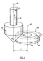
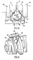
- the figure 3 represents an example of a cam 40 used in mounting the figure 1 .
- the cam 40 has a generally cylindrical shape. It comprises a central bore 43 intended to receive the drive shaft 30, as well as a keyway 44 formed from the bore 43 and intended to allow indexing of the cam 40 on the shaft 30.
- a helical chamfer 41 has been made by milling a circular edge of the cam 40.
- This cam is formed from a cylindrical piece of cross-section, one of whose circular edges is chamfered to form said inclined helical cam surface. relative to the axis of the cylindrical part, the ends of the helical surface joining with a recess surface of generally conical shape
- the milling operation is carried out using a conical cutter 100 whose cutting edges form an angle of 45 degrees relative to its axis of rotation 101.
- the cutter is mounted on a rotating machining spindle 102.
- a cylindrical piece 400 of revolution (shown in dashed lines) for forming the cam 40 is mounted on a turntable. It is arranged relative to the cutter 100 so that their axes 101 and 401 are parallel and have a spacing e given.
- the part 400 is animated during the milling operation of a rotational movement relative to its axis 401 (as indicated by the arrow R). Simultaneously, the cutter 100 is driven in a translation movement (indicated by the arrow T) along its axis 101.
- the translational movement is effected in a direction in which the cutter 100 moves away from the cylindrical part 400.
- piece 400 rotates 360 degrees while pin 102 is translated by a distance equal to the pitch of the helical chamfer to generate.
- This milling operation leads to the generation of the helical chamfer 41 oriented at 45 degrees with respect to the axis 401.
- the helical chamfer of the cam 40 forms a circumferential surface 41 which widens when it is traversed in the opposite direction to the milling and is connected at its ends by a recess of conical shape 45.
- This recess of conical shape is generated by the shape of the conical bur when taking the initial radial pass in the piece 400.
- the shape of the recess may vary depending on the initial setting path of the strawberry. If the conical cutter enters the workpiece 400 in a tangential pass, the recess obtained will be generally planar. If the conical cutter enters the workpiece 400 according to a skew grip, the recess obtained will be of generally planar shape with conical connection.
- the helical running surface must be obtained by a different method.
- a preliminary step of milling the cylindrical part with the aid of a cylindrical cutter in order first to obtain a helical surface oriented perpendicularly to the axis of the part.
- a step of milling the edge of the helical surface is carried out using a conical bur to make a helical chamfer oriented at 45 degrees with respect to the axis of the workpiece.
- the helical chamfer thus obtained forms a circumferential surface of constant width which is connected at its ends by a conical recess.
- the figure 5 represents the positioning of two cams 40 and 50 relative to one another on the drive shaft 30.
- the two cams 40 and 50 each have a surface 41, 51 of identical chamfer. They are positioned side-by-side on the drive shaft 30, so that their respective chamfer surfaces 41 and 51 face each other to form a helical raceway for the balls 22.
- the cams 40 and 50 are each The keyways 44 and 54 are positioned relative to the bore of the cams 40 and 50 so that the tapered recess surfaces 45 and 55 of the cams 40 are indexed to the shaft 30 by their keyway 44 or 54. and 50 are oppositely positioned opposite each other when they are mounted on the shaft 30.
- the tapered recess surfaces 45 and 55 of the two cams 40 and 50 advantageously form an enlarged zone 81 which accommodates the balls 22 and allows their recirculation.
- the shaft 30 of the actuator is rotated, the balls 22 roll on the race formed by the chamfer surfaces 41 and 51.
- a ball 22 reaches the recirculation zone 81 where both chamfer surfaces 41 and 51 have a maximum width, it is no longer in contact with the inner surface 21 of the outer tube 20 so that it no longer rolls.
- the ball 22 remains in the recirculation zone until it is pushed by the arrival of a next ball and thus automatically reengaged in the raceway.
- the nut 70 formed by the combination of cams 40, 50, 60 has the advantage of not requiring the formation of an internal recirculation path.
- the balls 22 are automatically "recycled” as soon as they reach the recirculation zone 81 joining the ends of a raceway.
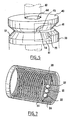
- the figure 6 illustrates the positioning of the cams 40, 50 and 60 successive relative to each other on the drive shaft 30. These cams are arranged so that the recirculation zones of the balls are not aligned. More specifically, the cams are oriented on the drive shaft 30 so that the recirculation zones are distributed angularly in a regular manner about the axis of the shaft 30 (axis of rotation and translation of the actuator). So, on the figure 6 , the nut comprising two tracks respectively formed by the cams 40, 50 and 50, 60, it has two recirculation zones which are arranged at 180 degrees relative to each other about the axis of the tree 30.
- the cams In the case of a nut comprising three raceways which would have three recirculation zones, the cams would be oriented so that the recirculation zones are arranged at 120 degrees from each other about the axis of the cam. tree 30.
- the cams In general, in the case of a nut comprising N raceways (formed by N pairs of cams), the cams would be oriented so that the recirculation zones are arranged at 360 / N degrees relative to each other. others around the axis of the tree 30.
- This feature makes it possible to avoid nutation movement of the inner tube 10 with respect to the outer tube 20, which can occur when the actuator comprises only one pair of cams (that is to say a single raceway) or when the recirculation zones are arranged aligned.
- the inner and outer tubes 10 are formed of relatively light material: for example composite material or plastic or light alloy.
- raceways are formed on the inner surface 21 of the outer tube 20. These raceways make it possible to reduce the Hertz pressure exerted by the balls 22 on the surface of the tube 20.
- runways can be formed by roller burnishing of the inner surface 21 of the tube 20.
- the rolling tracks may advantageously be formed by the balls 22 themselves during the rotation of the shaft 30.
- the balls 22 produce a plastic deformation of the surface 21 forming tracks of rolling.
- raceways makes it possible to apply compression forces that would not be able to withstand a smooth cylindrical surface.
- these tracks make it possible to increase in an apparent manner the coefficient of friction ball / outer tube.
- raceways make it possible not to apply excessive prestressing force on the balls.
- the balls being guided by the rolling tracks they can not slide relative to the outer tubular body 20.
- These rolling tracks have a helical pitch substantially equal to the helical pitch of the raceway formed in the nut 70.
- the actuator comprises in combination rolling tracks on the inner surface 21 of the outer tube 20 and a nut 70 having recirculation zones in the form of enlarged spaces.
- the inner and outer tubes 20 are also formed of relatively light material.
- Running tracks are formed on the inner surface of the outer tube 20.
- the rolling tracks are constituted by a high-strength steel wire 91 positioned helically inside the outer tube 20.
- the balls 22 roll in support on two successive turns of the wire 91.
- This variant allows to obtain a connection between the balls 22 and the tracks of the tube 20 mechanically positive (there is more friction but support).
- the longitudinal components of the bearing forces on the turns of the wire 91 are positive supports.
- the inner surface 21 of the outer tube 20 comprises a helical groove 24 for receiving the steel wire 91.
- This variant makes it possible to use aluminum, KEVLAR ⁇ , carbon fiber or molded plastic tubes, which guarantees the lightness of the final actuator structure obtained.
- the inner surface 21 of the outer tube 20 is smooth.
- Running tracks are formed on the inner surface of the outer tube 20. They are constituted by a first high-strength steel wire 91 positioned helically inside the outer tube 20 and on which the balls 22 abut.
- a second intermediate wire 92 having a diameter smaller than that of the first wire 91 extends between the turns of the first wire. This second wire 92 maintains the spacing between the turns of the first wire. It avoids in particular that the turns of the first wire 91 do not deviate during the passage of a ball 22.
- the balls 22 are not in contact with the intermediate wire 92.
- This implementation is particularly simple and avoids resorting to machining techniques of the outer tube 20.
- the figure 10 represents another variant of the invention in which rolling tracks are made by plastic deformation in a calibrated inner tube.
- the inner tube 93 is disposed in the outer tube 20 and welded thereto.
- the raceways in the inner tube 93 are made in the following manner.
- a roller or forming machine which comprises a roller holder provided with three rollers arranged at 120 degrees with respect to each other and oriented according to the helix angle of the track to be obtained.
- the inner tube 93 is fixed on a mandrel of shape close to the inner profile to be obtained.
- the roller holder is rotated.
- the tube 93 and the mandrel are driven in translation.
- the translational speed of the tube 93 is adjusted so that the translation distance is equal to the pitch of the helix at each turn of the roller holder.
- the operation can be done in one go and the tube 93 is then strongly hardened which makes the rigidity and the hardness of the running surface greater.
- the tube 93 is introduced into the outer tube 20.
- the figure 11 represents a welding step of the inner tube 93 in which the raceways are formed in the outer tube 20 of the actuator.
- a spot welder comprising an inner wheel 201 mounted on a shaft 203 and an outer motorized wheel 202.
- the inner wheel is inclined relative to the shaft 203 by an angle equal to the helix angle of the raceways.
- the welds are made at the bottom of the helical tracks in contact with the outer tube 20.
- the assembly thus formed is boxed and the axial deformation of the assembly is negligible. This small deformation guarantees a linearity of the transformation of the rotational movement into translation movement in the final actuator.
- each cam 40, 50 or 60 has a chamfer oriented at an angle less than or equal to 45 degrees with respect to the axis 401 of the cam, preferentially strictly less than 45 degrees and preferably about 35 degrees.
- This characteristic makes it possible to reduce the radial force which acts as a reaction support for the forces applied to the raceway.
- this feature facilitates the passage of balls over the edges of the tracks during their re-circulation. Indeed, the component of the force that allows the passage of a ball over a runway edge (formed for example by a wire) passes over the edge of the track.
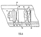
- the figure 12 represents a linear actuator telescopic type. This actuator is similar to that of the figure 1 . It comprises an inner tube 10 and an outer tube 20 whose diameter is greater than the diameter of the inner tube 10. The inner tube 10 extends in part in the outer tube 20. It also comprises a nut 70 consisting of a succession of cams 40, 50 and 60 of cylindrical general shapes.
- the linear actuator shown on the figure 12 further comprises a third tube 300 whose diameter is greater than that of the outer tube 20.
- the outer tube extends partly into the third tube 300.
- the nut 370 is rigidly connected to the outer tube 20 so that the outer tube 20 is adapted to drive in rotation a nut 370 comprising cams 340 and 350.
- the tubes 10 and 300 are locked in rotation relative to each other and are able to be driven to slide relative to each other in their longitudinal direction.
- the outer tube 20 is mounted floating, that is to say that it is blocked in rotation neither with the inner tube 10 nor with the third tube 300.
- the motor 2 of the actuator of the figure 12 When the motor 2 of the actuator of the figure 12 is in operation, it rotates the nut 70 comprising the cams 40, 50 and 60. The balls 22 then roll between their raceway and the inner surface of the intermediate tube 20. The tubes 10 and 300 being locked in rotation l relative to each other, the rotation of the nut 70 causes the translation of the inner tube 10 relative to the outer tube assembly 20 and third tube 300. This translation is limited by a stop.
- the tubes 10 and 20 are then rotated simultaneously.
- the outer tube 20 then rotates the nut 370 comprising cams 340 and 350.
- the balls 22 then roll between their race formed by the cams 340 and 350 and the inner surface of the third tube 300.
- the tubes 10 and 300 being locked in rotation relative to each other, the rotation of the nut 370 causes the translation of the inner tube 10 and outer tube 20 relative to the third tube 300.
- the telescopic actuator thus produced deploys in two stages.
- the inner tube 10 is translated relative to the outer tube 20 and the third tube 300
- the inner and outer tubes 20 and 20 are translated relative to the third tube 300.
- This deployment in two stages is due to the fact that the torque necessary to drive the nut 370 in rotation relative to the third tube is greater than the torque necessary to drive the nut 70 in rotation with respect to the outer tube.
- the deployment can also be done randomly depending on the friction couples appearing in the mechanism.
- Such a telescopic actuator has the advantage of being able to reach greater deployment lengths than with a simple actuator as represented on the figure 1 .
- the nut 70 comprises two pairs of cams and the nut 370 comprises a single pair of cams.
- the figure 13 represents the actuator of the figure 12 in the deployed position.
- the tubes 20 and 300 each have on their inner surfaces running tracks. These tracks preferably have the same pitch. Thus, the deployment of the actuator will be at constant speed. In addition, it will be possible by counting the number of engine revolutions to know the exact position of the actuator.
- the deployment speed of the actuator will vary depending on the tube that will be moving at a given moment.
- a telescopic actuator comprising a plurality of tubes adapted to be driven in translation relative to one another, it is possible to choose to set different steps of tracks for the different tubes.
- the figure 14 represents a ball 22 of center O held between the chamfer surfaces 41 and 51 cams 40 and 50 and a raceway formed for example by two wires 92 and 94.
- the contact points between the ball 22 and the cam 40, the cam 50, the wire 92 and the wire 94 are respectively referenced B, D, C and A.
- the angle between the plane P of the right section of the actuator passing through O and the line (OA) is noted ⁇ 1 and the angle between the plane P and the line (OB) is denoted ⁇ 2 .
- the forces exerted on the ball by the cams and the raceway are denoted F A , F B , F C and F D.
- the cams 40 and 50 are rotated so that the ball 22 reaches an enlarged recirculation zone as illustrated in FIG. figure 15 . From this moment, the ball 22 is no longer in contact with the cam 50 so that it is no longer in equilibrium because no force is applied in D. The ball 22 is subjected to a force giving it an acceleration enabling it to disengage from the raceway and to cross the wire 94 to position itself on the adjacent track.
- the passage of the ball 22 from one track to the other can be realized only if ⁇ 1 ⁇ 2 so that the resultant of the efforts on the ball passes over the wire 94.
- ⁇ 2 can be chosen between 50 and 60 degrees, preferably 55 degrees.
- the cam 40 has a surface 41 of helical chamfer oriented at 35 degrees with respect to the plane P.
- a cam having such a helical chamfer can be obtained by machining a cylindrical part with a conical cutter having a half-angle at the apex of 55 degrees.
- the figure 16 represents the positioning of two cams 40 and 50 relative to each other.
- the plane Q extends transversely to the plane of the diagram and passes through the axis of rotation of the nut 70 including the two cams 40 and 50.
- the cams 40 and 50 are identical. They are arranged opposite each other so that the rolling surfaces 41 and 51 face each other.
- the cams are indexed by their keyways (see figure 5 ), the keyways extending in the plane Q.
- the keyways are positioned to form an angle ⁇ relative to the mark consisting of an end of the helical surface corresponding to the plane of attack of the cutter.
- the angle ⁇ can be adjusted in order to minimize the space of evolution of the balls in the recirculation zone 81 to avoid the presence of several balls simultaneously in this zone and to keep the greatest possible number of "working" balls ".
- the adjustment of the angle ⁇ depends in particular on the pitch of the raceway, the orientation of the cam surfaces 41 and 51, the diameter of the balls 22, the diameter of the son 92 and 94 used for the realization of the tracks.
- This angle ⁇ is to determine the volumes in which the center O of a ball moves when it is respectively resting on one of the cam surfaces, resting on the other cam surface and in bearing on the rolling tracks. The intersection of these volumes represents the space in which the ball is guided. This space can be modified by varying the angle ⁇ . The intersection space must be both wide enough for a ball to enter the re-circulation zone and move in the helical raceway and sufficiently restricted to prevent multiple balls from being simultaneously in the area. The shape of the space obtained depends on the angle ⁇ and also on the shape of the recess surfaces of the cams.
Landscapes
- Engineering & Computer Science (AREA)
- General Engineering & Computer Science (AREA)
- Mechanical Engineering (AREA)
- Transmission Devices (AREA)
Abstract
Description
L'invention concerne le domaine des actionneurs linéaires mécaniques, et notamment des actionneurs mécaniques entraînés par un moteur électrique (actionneurs électromécaniques).The invention relates to the field of mechanical linear actuators, and in particular mechanical actuators driven by an electric motor (electromechanical actuators).
Le développement des actionneurs linéaires électromécaniques est lié aux besoins dans des domaines tels que la robotique et la domotique. En effet, dans ces domaines les vérins électromécaniques concurrencent les vérins classiques, hydrauliques ou pneumatiques, car ils sont plus facilement commandables, plus précis et ne nécessitent pas de source de fluide externe.The development of linear electromechanical actuators is related to needs in areas such as robotics and home automation. Indeed, in these areas the electromechanical cylinders compete with conventional cylinders, hydraulic or pneumatic, because they are more easily controllable, more precise and do not require an external source of fluid.
Ces actionneurs électromécaniques comprennent généralement une vis à billes sur laquelle est monté un écrou. L'écrou est entraîné en rotation par un motoréducteur extérieur. La rotation de l'écrou entraîne la translation de la vis.These electromechanical actuators generally comprise a ball screw on which is mounted a nut. The nut is rotated by an external geared motor. The rotation of the nut causes the translation of the screw.
L'inconvénient de ces actionneurs électromécaniques est qu'ils sont relativement encombrants.The disadvantage of these electromechanical actuators is that they are relatively bulky.
En outre, le coût des vis à billes étant généralement élevé vis-à-vis des autres pièces mécaniques qu'ils contiennent, ces actionneurs restent relativement coûteux.In addition, the cost of ball screws being generally high vis-à-vis the other mechanical parts they contain, these actuators are relatively expensive.
On connaît, en particulier par le document
Un but de l'invention est de proposer une structure d'actionneur compacte et dont la réalisation serait simplifiée par rapport aux structures d'actionneurs de l'art antérieur.An object of the invention is to provide a compact actuator structure and whose implementation would be simplified with respect to actuator structures of the prior art.
A cet effet, l'invention concerne un actionneur selon l'objet de la revendication indépendante 1.For this purpose, the invention relates to an actuator according to the subject of
Le fait que l'actionneur comprend un écrou interne permet de positionner le moteur des moyens d'entraînement de l'écrou à l'intérieur d'un deuxième corps. En outre, le chemin de re-circulation peut être intégré à l'écrou. Cette disposition conduit à une structure compacte d'actionneur et dont l'aspect extérieur s'apparente aux actionneurs pneumatiques. En particulier, l'actionneur ne laisse pas apparaître de dispositif motoréducteur externe. L'actionneur proposé est donc particulièrement compact relativement à l'effort qu'il est capable de générer.The fact that the actuator comprises an inner nut makes it possible to position the motor of the drive means of the nut inside a second body. In addition, the recirculation path can be integrated with the nut. This arrangement leads to a compact actuator structure and whose external appearance is similar to pneumatic actuators. In particular, the actuator does not reveal an external geared motor device. The proposed actuator is particularly compact relative to the effort it is able to generate.
En outre, l'utilisation d'une structure tubulaire confère à l'actionneur une meilleure résistance au flambage qu'un actionneur classique présentant un écrou extérieur monté autour d'une vis intérieure.In addition, the use of a tubular structure gives the actuator a better buckling resistance than a conventional actuator having an outer nut mounted around an inner screw.
Dans une mise en oeuvre de l'invention, les billes sont montées entre le chemin et le premier corps tubulaire avec une précontrainte radiale déterminée.In one implementation of the invention, the balls are mounted between the path and the first tubular body with a predetermined radial prestressing.
Le fait que les billes soient montées avec précontrainte permet d'obtenir un actionneur linéaire capable de transmettre des efforts importants par rapport à ses dimensions.The fact that the balls are mounted with prestressing makes it possible to obtain a linear actuator capable of transmitting significant forces with respect to its dimensions.
Selon l'invention, le chemin de roulement comprend une portion hélicoïdale s'étendant autour de l'écrou selon un angle inférieur à 360 degrés et une portion élargie joignant les extrémités adjacentes de la portion hélicoïdale, ladite zone élargie constituant une zone de re-circulation des billes.According to the invention, the raceway comprises a helicoidal portion extending around the nut at an angle of less than 360 degrees and an enlarged portion joining the adjacent ends of the helical portion, said enlarged area constituting a zone of rotation. circulation of the balls.
Ceci présente l'avantage de ne pas nécessiter la formation d'un chemin de re-circulation interne dans l'écrou. Les billes sont automatiquement « recyclées » dès qu'elles atteignent la zone de re-circulation.This has the advantage of not requiring the formation of an internal recirculation path in the nut. The balls are automatically "recycled" as soon as they reach the recirculation zone.
En outre, la surface intérieure du premier corps tubulaire présente des pistes de roulement hélicoïdales ayant pour fonction de guider des billes. Les zones élargies de re-circulation permettent le passage des billes d'une piste de roulement à une piste adjacente par-dessus un bord de piste lors de leur recirculation.In addition, the inner surface of the first tubular body has helical rolling tracks whose function is to guide balls. The widened re-circulation zones allow the balls of a running track to pass to an adjacent track over a runway edge during their recirculation.
L'écrou comprend plusieurs éléments alignés, de forme générale cylindrique, présentant chacun au moins un chanfrein formant une surface de came hélicoïdale, les chanfreins formant deux à deux des chemins de roulement hélicoïdaux dans lesquels sont positionnées des billes. Chaque élément est formé à partir d'une pièce cylindrique de section droite dont l'une des arêtes circulaires est chanfreinée pour former ladite surface de came hélicoïdale inclinée par rapport à l'axe de la pièce cylindrique, les extrémités de la surface hélicoïdale se rejoignant par une surface de décrochement de forme générale de préférence conique.The nut comprises a plurality of aligned elements of generally cylindrical shape, each having at least one chamfer forming a helical cam surface, the chamfers forming pairs of helical raceways in which balls are positioned. Each element is formed from a cylindrical piece of cross-section, one of whose circular edges is chamfered to form said helical cam surface inclined with respect to the axis of the cylindrical piece, the ends of the helical surface joining together by a recess surface of generally conical shape.
Chaque élément de l'écrou est formé à partir d'une pièce cylindrique de section droite c'est-à-dire que la pièce cylindrique est limitée par deux plans parallèles orthogonaux à son axe de révolution. Il s'agit d'une forme simple. La forme des éléments est par conséquent plus facile à générer que dans l'art antérieur.Each element of the nut is formed from a cylindrical piece of cross section that is to say that the cylindrical piece is limited by two parallel planes orthogonal to its axis of revolution. This is a simple form. The shape of the elements is therefore easier to generate than in the prior art.
Selon la technique de réalisation du chanfrein, la surface de décrochement peut également présenter une forme générale convexe, concave, plane, cylindrique, plane à raccordement conique ou à raccordement cylindrique ou autre.According to the technique of making the chamfer, the recess surface may also have a generally convex, concave, planar, cylindrical shape, plane with conical connection or cylindrical connection or other.
Avantageusement, chaque surface de came hélicoïdale forme un décrochement et deux éléments sont positionnés l'un par rapport à l'autre de sorte que leurs décrochements se trouvent l'un en face de l'autre, lesdits décrochements formant la zone de re-circulation des billes.Advantageously, each helical cam surface forms a recess and two elements are positioned relative to one another so that their recesses are opposite each other, said recesses forming the recirculation zone. marbles.
Avantageusement, la précontrainte exercée sur les billes est engendrée par serrage des éléments entre eux.Advantageously, the prestressing exerted on the balls is generated by clamping the elements together.
A cet effet, l'actionneur peut comprendre un écrou de réglage des éléments pour régler la précontrainte exercée sur les billes.For this purpose, the actuator may include an adjusting nut of the elements to adjust the preload exerted on the balls.
L'effort pouvant être fourni par l'actionneur dépend directement de la précontrainte appliquée aux billes et réglée par l'écrou de réglage.The force that can be supplied by the actuator depends directly on the preload applied to the balls and adjusted by the adjusting nut.
Avantageusement, l'actionneur comprend des moyens élastiques interposés entre l'écrou de réglage et les éléments de l'écrou par l'intermédiaire desquels l'écrou de réglage exerce une précontrainte sur les éléments.Advantageously, the actuator comprises elastic means interposed between the adjusting nut and the elements of the nut through which the adjusting nut exerts a prestress on the elements.
De préférence, le moteur est un moteur électrique ou hydraulique.Preferably, the motor is an electric or hydraulic motor.
Le procédé d'obtention de l'élément d'écrou est simple à mettre en oeuvre avec des moyens d'usinage traditionnels.The method of obtaining the nut element is simple to implement with traditional machining means.
D'autres caractéristiques et avantages ressortiront encore de la description qui suit, laquelle est purement illustrative et non limitative et doit être lue en regard des figures annexées parmi lesquelles:
- la
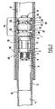
figure 1 représente en coupe longitudinale, un exemple de structure d'actionneur, dans laquelle les moyens d'entraînement comprennent un moteur électrique, étant précisé que ce mode de réalisation correspondant à cettefigure 1 ne fait pas partie des modes de réalisation revendiqués et est seulement décrit ci-après à titre informatif ; - la
figure 2 est un schéma représentatif d'une bille précontrainte, - la
figure 3 est une vue en perspective d'une came constitutive de l'écrou, - la
figure 4 est un schéma représentatif d'une étape de génération d'une surface de came hélicoïdale, - la
figure 5 est un schéma représentatif du positionnement de deux cames l'une par rapport à l'autre sur l'arbre d'entraînement de l'actionneur, - la
figure 6 représente schématiquement le positionnement de deux couples de cames l'un par rapport à l'autre, dans lequel les zones de recirculation des billes sont réparties régulièrement autour de l'arbre d'entraînement, - la
figure 7 représente un exemple de surface intérieure du corps tubulaire présentant des pistes de roulement formées par un fil enroulé en hélice, - les
figures 8 et 9 représentent schématiquement des pistes de roulement formés par un premier fil enroulé et un deuxième fil intermédiaire disposé entre les spires du premier fil, - la
figure 10 représente schématiquement des pistes de-roulement formées par déformation plastique d'un tube interne disposé dans le corps tubulaire, - la
figure 11 représente schématiquement une étape de soudure du tube interne dans le corps tubulaire, - la
figure 12 représente en coupe longitudinale, une structure d'actionneur de type télescopique, - la
figure 13 représente l'actionneur de lafigure 12 en position déployée, - la
figure 14 représente schématiquement le positionnement d'une bille en appui entre l'écrou et une piste de roulement, - la
figure 15 est une vue en coupe et en perspective des billes lorsqu'elles parviennent dans une zone de re-circulation, - la
figure 16 est un schéma représentatif du positionnement de deux cames l'une par rapport à l'autre.
- the
figure 1 represents in longitudinal section, an example of an actuator structure, in which the drive means comprise an electric motor, it being specified that this embodiment corresponding to thisfigure 1 is not one of the claimed embodiments and is only hereinafter described for informational purposes; - the
figure 2 is a representative diagram of a prestressing ball, - the
figure 3 is a perspective view of a cam constituting the nut, - the
figure 4 is a representative diagram of a step of generating a helical cam surface, - the
figure 5 is a diagram representative of the positioning of two cams relative to each other on the drive shaft of the actuator, - the
figure 6 schematically represents the positioning of two pairs of cams relative to each other, in which the recirculation zones of the balls are evenly distributed around the drive shaft, - the
figure 7 represents an example of an inner surface of the tubular body having rolling tracks formed by a wire wound helically, - the
Figures 8 and 9 schematically represent rolling tracks formed by a first wound wire and a second intermediate wire disposed between the turns of the first wire, - the
figure 10 schematically represents rolling tracks formed by plastic deformation of an inner tube disposed in the tubular body, - the
figure 11 schematically represents a step of welding the inner tube in the tubular body, - the
figure 12 represents in longitudinal section, a telescopic type actuator structure, - the
figure 13 represents the actuator of thefigure 12 in the deployed position, - the
figure 14 schematically represents the positioning of a ball bearing between the nut and a running track, - the
figure 15 is a sectional and perspective view of the balls when they arrive in a recirculation zone, - the
figure 16 is a diagram representative of the positioning of two cams relative to each other.
Sur la
A cet effet, l'actionneur comprend un mécanisme d'entraînement comprenant un arbre d'entraînement 30 s'étendant selon l'axe longitudinal des tubes 10 et 20. L'arbre 30 est entraîné en rotation par un moteur électrique 2 fixé à l'une de ses extrémités et positionné dans le tube intérieur 10. Le moteur 2 et l'arbre 30 sont maintenus dans le tube intérieur 10 par l'intermédiaire d'un support cylindrique 3 fixé au tube intérieur.For this purpose, the actuator comprises a drive mechanism comprising a
Par ailleurs, l'arbre 30 est guidé dans le tube intérieur 10 par l'intermédiaire de deux roulements à billes 7 et 9 dont la bague intérieure est montée sur l'arbre 30 et la bague extérieure vient en appui sur la surface intérieure 11 du tube intérieure 10. Les deux roulements 7 et 9 sont maintenus à distance par une entretoise 8 sous la forme d'un manchon cylindrique venant en appui sur les bagues intérieures des roulements 7 et 9 ainsi que par l'intermédiaire d'une entretoise 12 goupillées dans le tube intérieur 10 et venant en appui sur les bagues extérieures des roulements 7 et 9. La reprise des efforts axiaux exercés sur les roulements peut se faire soit par l'intermédiaire de l'entretoise 12, soit par tout autre moyen équivalent (par exemple des circlips bloquant le roulement).Furthermore, the
L'arbre 30 supporte en outre un écrou de réglage 4, un ensemble de rondelles Belleville 5, une première rondelle de serrage 6 positionnées entre le support 3 du moteur et le roulement 7. La rondelle de serrage 6 prend appui sur la cage interne du roulement 7. L'arbre 30 supporte également une deuxième rondelle de serrage 1 et un écrou à billes 70, positionnés entre le roulement 9 et un élément de butée 31 en extrémité de l'arbre 30.The
L'écrou 70 est constitué d'une succession de cames 40, 50 et 60 de formes générales cylindriques montées alignées sur l'arbre 30 et bloquées en rotation par rapport à l'arbre par une clavette. Les cames 40, 50, 60 présentent des chanfreins hélicoïdaux 41, 51 et 52, 62, orientés à 45° par rapport à l'axe de l'arbre 30. Ces chanfreins 41, 51, 52, 62 forment deux à deux des chemins de roulement hélicoïdaux dans lesquels sont positionnés des billes 22. Les billes 22 sont en contact d'une part avec deux surfaces de chanfreins opposés, 41 et 51, ou 52 et 62 et d'autre part avec la surface intérieure lisse 21 du tube extérieur 20. L'effort radial appliqué sur les billes 22 est réglé par serrage de l'écrou 4. L'écrou de réglage 4 applique un effort de compression sur les rondelles Belleville 5 selon la direction longitudinale de l'arbre 30. Cet effort de compression est transmis aux cames 40, 50, 60 par l'intermédiaire la rondelle de serrage 6 qui transmet et répartit l'effort de serrage sur les cages internes des roulements 7 et 9 et sur la rondelle de serrage 1. Les cames 40, 50, 60 se trouvent donc en compression entre la rondelle de serrage 1, les billes 22 et l'élément de butée 31 en extrémité de l'arbre 30. Par serrage des cames 40, 50, 60, l'écrou de réglage 4 permet avantageusement de régler une précontrainte exercée sur les billes 22.The
L'actionneur de la
L'effort pouvant être fourni par l'actionneur de la
Toutefois, l'effort de précontrainte pouvant être appliqué aux billes 22 reste limité par la pression de Hertz que peuvent subir la surface des cames 40, 50, 60 et la surface intérieure 21 du tube extérieur 20.However, the prestressing force that can be applied to the
Lorsque le moteur 2 de l'actionneur de la
Ainsi que représenté sur la
L'actionneur linéaire de la
- montage des différents éléments sur l'arbre 30 :
cames rondelle 1,roulement 9, entretoises 8 et 12,roulement 7,rondelle 6, rondellesBelleville 5, écrou de réglage 4, - introduction de l'extrémité de l'arbre 30 supportant les cames 40, 50, 60 dans le
tube extérieur 20, les billes 22 étant positionnées dans les chemins de roulement, - serrage de l'écrou 4 qui entraîne le rapprochement des cames 40, 50, 60 et la précontrainte des billes 22 entre les surfaces des chanfreins et la surface intérieure 21 du
tube extérieure 20.
- mounting the various elements on the shaft 30:
cams washer 1,bearing 9, spacers 8 and 12,bearing 7,washer 6,Belleville washers 5, adjustingnut 4, - introduction of the end of the
shaft 30 supporting thecams outer tube 20, theballs 22 being positioned in the raceways, - tightening the
nut 4 which brings thecams balls 22 into contact between the surfaces of the chamfers and theinner surface 21 of theouter tube 20.
La
Ainsi qu'illustré sur la
Des opérations classiques de traitement thermique et de rectification peuvent ensuite être réalisées sur la surface hélicoïdale 41 obtenue (par exemple meulage de la surface hélicoïdale).Conventional heat treatment and grinding operations can then be performed on the
Comme on peut le voir sur le
Bien entendu, des variantes du mode de réalisation précédemment décrit sont envisageables. En particulier, la forme du décrochement peut varier en fonction de la trajectoire de prise de passe initiale de la fraise. Si la fraise conique pénètre dans la pièce 400 selon une prise de passe tangentielle, le décrochement obtenu sera de forme générale plane. Si la fraise conique pénètre dans la pièce 400 selon une prise de passe oblique, le décrochement obtenu sera de forme générale plane à raccordement conique.Of course, variants of the embodiment described above are possible. In particular, the shape of the recess may vary depending on the initial setting path of the strawberry. If the conical cutter enters the
Il est également possible d'utiliser une fraise cylindrique dont l'axe de rotation serait incliné par rapport à l'axe de la pièce cylindrique et selon la trajectoire de prise de passe initiale, d'obtenir un décrochement de forme générale cylindrique, plane ou plane à raccordement cylindrique.It is also possible to use a cylindrical cutter whose axis of rotation is inclined with respect to the axis of the cylindrical part and according to the initial catch trajectory, to obtain a recess of generally cylindrical, flat or plane with cylindrical connection.
En outre, lorsque le pas du chemin de roulement est grand vis à vis du diamètre des cames, la surface de roulement hélicoïdale doit être obtenue par un procédé différent. Par exemple, on peut réaliser une étape préalable de fraisage de la pièce cylindrique à l'aide d'une fraise cylindrique pour obtenir en premier lieu une surface hélicoïdale orientée perpendiculairement à l'axe de la pièce. Puis, on effectue une étape de fraisage du bord de la surface hélicoïdale à l'aide d'une fraise conique pour réaliser un chanfrein hélicoïdal orienté à 45 degrés par rapport à l'axe de la pièce. Le chanfrein hélicoïdal ainsi obtenu forme une surface circonférentielle de largeur constante qui se raccorde à ses extrémités par un décrochement conique.In addition, when the pitch of the raceway is large with respect to the diameter of the cams, the helical running surface must be obtained by a different method. For example, it is possible to carry out a preliminary step of milling the cylindrical part with the aid of a cylindrical cutter in order first to obtain a helical surface oriented perpendicularly to the axis of the part. Then, a step of milling the edge of the helical surface is carried out using a conical bur to make a helical chamfer oriented at 45 degrees with respect to the axis of the workpiece. The helical chamfer thus obtained forms a circumferential surface of constant width which is connected at its ends by a conical recess.
La
Les surfaces de décrochement conique 45 et 55 des deux cames 40 et 50 forment avantageusement une zone élargie 81 qui accueille les billes 22 et permet leur re-circulation. Lorsque l'arbre 30 de l'actionneur est entraîné en rotation, les billes 22 roulent sur le chemin de roulement formé par les surfaces de chanfrein 41 et 51. Lorsqu'une bille 22 parvient dans la zone 81 de re-circulation où les deux surfaces de chanfrein 41 et 51 présentent une largeur maximale, elle n'est plus en contact avec la surface intérieure 21 du tube extérieur 20 de sorte qu'elle ne roule plus. La bille 22 reste dans la zone de re-circulation jusqu'à ce qu'elle soit poussée par l'arrivée d'une bille suivante et ainsi réengagée automatiquement dans le chemin de roulement.The tapered recess surfaces 45 and 55 of the two
Sur la
La
Dans le cas d'un écrou comprenant trois chemins de roulement qui présenterait trois zones de re-circulation, les cames seraient orientées de sorte que les zones de re-circulation soient disposées à 120 degrés les unes des autres autour de l'axe de l'arbre 30.In the case of a nut comprising three raceways which would have three recirculation zones, the cams would be oriented so that the recirculation zones are arranged at 120 degrees from each other about the axis of the cam.
De manière générale, dans le cas d'un écrou comprenant N chemins de roulement (formés par N paires de cames), les cames seraient orientées de sorte que les zones de re-circulation soient disposées à 360/N degrés les unes par rapport aux autres autour de l'axe de l'arbre 30.In general, in the case of a nut comprising N raceways (formed by N pairs of cams), the cams would be oriented so that the recirculation zones are arranged at 360 / N degrees relative to each other. others around the axis of the
Cette caractéristique permet d'éviter un mouvement de nutation du tube intérieur 10 par rapport au tube extérieur 20, pouvant se produire lorsque l'actionneur ne comporte qu'une seule paire de cames (c'est à dire un seul chemin de roulement) ou lorsque les zones de re-circulation sont disposées alignées.This feature makes it possible to avoid nutation movement of the
Dans une variante de l'actionneur linéaire de la
Dans toutes les variantes de l'actionneur revendiquées, des pistes de roulement sont formées sur la surface intérieure 21 du tube extérieur 20. Ces pistes de roulement permettent de réduire la pression de Hertz exercée par les billes 22 sur la surface du tube 20. Les pistes de roulement peuvent être formées par galetage de la surface intérieure 21 du tube 20. Les pistes de roulement peuvent avantageusement être formées par les billes 22 elles-mêmes lors de la rotation de l'arbre 30. Les billes 22 produisent une déformation plastique de la surface 21 en formant des pistes de roulement.In all the variants of the claimed actuator, raceways are formed on the
Dans le cas où le tube extérieur 20 est en alliage léger, après avoir formé les pistes de roulement, on applique à la surface 21 du tube 20 un traitement de céramisation destiné à durcir cette surface en profondeur (de 0,1 à 0,2 mm).In the case where the
La constitution de pistes de roulement permet d'appliquer des efforts de compression que ne supporterait-pas une surface cylindrique lisse. En outre, ces pistes permettent d'augmenter de façon apparente le coefficient de frottement bille/tube extérieur.The formation of raceways makes it possible to apply compression forces that would not be able to withstand a smooth cylindrical surface. In addition, these tracks make it possible to increase in an apparent manner the coefficient of friction ball / outer tube.
Alternativement, les pistes de roulement permettent de ne pas appliquer d'effort de précontrainte trop important sur les billes. Les billes étant guidées par les pistes de roulement, elles ne peuvent glisser par rapport au corps tubulaire extérieur 20.Alternatively, the raceways make it possible not to apply excessive prestressing force on the balls. The balls being guided by the rolling tracks, they can not slide relative to the outer
Ces pistes de roulement présentent un pas hélicoïdal sensiblement égal au pas hélicoïdal du chemin de roulement formé dans l'écrou 70.These rolling tracks have a helical pitch substantially equal to the helical pitch of the raceway formed in the
Dans cette variante, l'actionneur comprend en combinaison des pistes de roulement sur la surface intérieure 21 du tube extérieur 20 et un écrou 70 présentant des zones de re-circulation sous forme d'espaces élargis. Grâce à cette structure, lorsqu'une bille parvient dans une zone de re-circulation, elle pénètre radialement vers l'intérieur de l'écrou 70 de sorte qu'elle n'est plus en contact avec l'une des pistes formées dans le tube extérieur 20. Ainsi, lorsqu'elle est « recyclée », la bille passe d'une piste de roulement à une piste adjacente par dessus un bord de piste, ce passage d'une piste à l'autre étant possible grâce à l'espace élargi constituant la zone de re-circulation.In this variant, the actuator comprises in combination rolling tracks on the
Dans une autre variante encore de l'actionneur de la
Cette variante permet d'utiliser des tubes en aluminium, en KEVLAR©, en fibres de carbone ou en matière plastique moulée, ce qui garantit la légèreté de-la structure d'actionneur final obtenue.This variant makes it possible to use aluminum, KEVLAR ©, carbon fiber or molded plastic tubes, which guarantees the lightness of the final actuator structure obtained.
Dans une mise en oeuvre représentée sur les
La
Les pistes de roulement dans le tube interne 93 sont réalisées de la manière suivante. On utilise par exemple une machine à galeter ou à former qui comprend un porte-galet muni de trois galets disposés à 120 degrés les uns par rapport aux autres et orientés suivant l'angle d'hélice de la piste à obtenir. Le tube interne 93 est fixé sur un mandrin de forme proche du profil intérieur à obtenir. Le porte-galet est entraîné en rotation. Simultanément, le tube 93 et le mandrin sont entraînés en translation. La vitesse de translation du tube 93 est réglée de sorte que la distance de translation soit égale au pas de l'hélice à chaque tour du porte-galet. L'opération peut se faire en une seule fois et le tube 93 est alors fortement écroui ce qui rend la rigidité et la dureté de la surface de roulement plus grande. Une fois formé, le tube 93 est introduit dans le tube extérieur 20.The raceways in the
La
Dans le cas où des pistes de roulement sont formées sur la surface intérieure du tube extérieur 20, chaque came 40, 50 ou 60 présente un chanfrein orienté selon un angle inférieur ou égal à 45 degrés par rapport à l'axe 401 de la came, préférentiellement strictement inférieur à 45 degrés et de préférence environ 35 degrés. Cette caractéristique permet de diminuer l'effort radial qui sert d'appui de réaction des forces appliquées à la piste de roulement. En outre, cette caractéristique facilite le passage des billes par dessus les bords des pistes lors de leur re-circulation. En effet, la composante de la force qui permet le passage d'une bille par dessus un bord de piste (formé par exemple par un fil) passe au-dessus du bord de piste.In the case where rolling tracks are formed on the inner surface of the
La
L'actionneur linéaire représenté sur la
Les tubes 10 et 300 sont bloqués en rotation l'un par rapport à l'autre et sont aptes à être entraînés pour coulisser l'un par rapport à l'autre selon leur direction longitudinale. Le tube extérieur 20 est monté flottant, c'est à dire qu'il n'est bloqué en rotation ni avec le tube intérieur 10 ni avec le troisième tube 300.The
Lorsque le moteur 2 de l'actionneur de la
Lorsque les tubes intérieur 10 et extérieur 20 sont en butée l'un par rapport à l'autre, les tubes 10 et 20 sont alors entraînés en rotation simultanément. Le tube extérieur 20 entraîne alors en rotation l'écrou 370 comprenant des cames 340 et 350. Les billes 22 roulent alors entre leur chemin de roulement formé par les cames 340 et 350 et la surface interne du troisième tube 300. Les tubes 10 et 300 étant bloqués en rotation l'un par rapport à l'autre, la rotation de l'écrou 370 entraîne la translation de l'ensemble tube intérieur 10 et tube extérieur 20 par rapport au troisième tube 300.When the
Il en résulte que l'actionneur télescopique ainsi réalisé se déploie en deux temps. Dans un premier temps, le tube intérieur 10 se translate par rapport aux tube extérieur 20 et troisième tube 300, puis dans un deuxième temps, les tubes intérieur 10 et extérieur 20 se translatent par rapport au troisième tube 300. Ce déploiement en deux temps est dû au fait que le couple nécessaire pour entraîner l'écrou 370 en rotation par rapport au troisième tube est supérieur au couple nécessaire pour entraîner l'écrou 70 en rotation par rapport au tube extérieur.As a result, the telescopic actuator thus produced deploys in two stages. In a first step, the
Le déploiement peut également se faire de manière aléatoire en fonction des couples de frottement apparaissant dans le mécanisme.The deployment can also be done randomly depending on the friction couples appearing in the mechanism.
Un tel actionneur télescopique présente l'avantage de pouvoir atteindre des longueurs de déploiement plus importantes qu'avec un actionneur simple tel que représenté sur la
Dans l'actionneur représenté à la
La
Les tubes 20 et 300 présentent chacun sur leurs surfaces intérieures des pistes de roulement. Ces pistes présentent de préférence le même pas. Ainsi, le déploiement de l'actionneur se fera à vitesse constante. En outre, il sera possible en comptant le nombre de tour du moteur de connaître la position exacte de l'actionneur.The
Si les pistes des tubes 20 et 300 présentent des pas différents, alors la vitesse de déploiement de l'actionneur variera selon le tube qui sera en mouvement à un instant donné.If the tracks of the
De manière générale, dans un actionneur télescopique comprenant une pluralité de tubes aptes à être entraînés en translation les uns par rapport aux autres, on peut choisir de fixer des pas différents de pistes pour les différents tubes. On obtient ainsi un actionneur télescopique qui se déploie avec des valeurs de coefficient de réduction moteur/mouvement programmables séquentiellement sur la course totale de l'actionneur. Cette caractéristique permet d'adapter l'évolution du couple moteur fourni en fonction du profil de la charge subie par l'actionneur au cours de son déploiement, ce profil étant déterminé par tronçons.Generally, in a telescopic actuator comprising a plurality of tubes adapted to be driven in translation relative to one another, it is possible to choose to set different steps of tracks for the different tubes. This results in a telescopic actuator that deploys with motor / motion reduction coefficient values sequentially programmable over the total travel of the actuator. This characteristic makes it possible to adapt the evolution of the engine torque supplied as a function of the load profile experienced by the actuator during its deployment, this profile being determined in sections.
Si l'on souhaite que les tubes se déploient dans un ordre donné, il est possible d'ajouter des moyens de freinage en rotation des tubes les uns par rapport aux autres (par exemple un ou plusieurs joint(s) torique(s) frottant sur le tube) pour que ceux-ci se déploient séquentiellement.If it is desired that the tubes unfold in a given order, it is possible to add means of rotationally braking the tubes relative to each other (for example one or more O-ring (s) rubbing on the tube) so that they unfold sequentially.
La description qui précède concerne un exemple d'actionneur linéaire dans lequel les moyens d'entraînement de l'écrou comprennent un moteur électrique 2. On comprendra qu'il est bien entendu possible d'utiliser d'autres types de moyens d'entraînement : moteur hydraulique ou autre.The foregoing description relates to an example of linear actuator in which the drive means of the nut comprise an
On va maintenant décrire plus en détail le passage d'une bille d'une piste de roulement à l'autre dans le cas d'un actionneur comportant un tube extérieur 20 dont la surface intérieure présente des pistes de roulement.We will now describe in more detail the passage of a ball from one raceway to another in the case of an actuator comprising an
La
Si α1 = α2, on a FA=FB, de sorte que la bille est en équilibre et les forces FC et FD sont nulles.If α 1 = α 2 , we have F A = F B , so that the ball is in equilibrium and the forces F C and F D are zero.
Si α1 > α2, on a FA+FB+FC=0 et la force FD exercée par la came 50 est nulle.If α 1 > α 2 , then F A + F B + F C = 0 and the force F D exerted by the
Si α1 < α2, on a FA+FB+FD=0 et la force FC exercée par la came 40 est nulle.If α 1 <α 2 , then F A + F B + F D = 0 and the force F C exerted by the
Les cames 40 et 50 sont entraînées en rotation de sorte que la bille 22 parvient à une zone élargie de re-circulation ainsi qu'illustré sur la
Le passage de la bille 22 d'une piste à l'autre ne peut se réaliser que si α1 < α2 de sorte que la résultante des efforts sur la bille passe au-dessus du fil 94.The passage of the
En outre, si on tient compte des frottements qui s'exercent sur la bille 22 et que l'on note ϕ1 et ϕ2 les angles de frottement entre la bille et le fil 94 et entre la bille et la came 40, une condition pour que le passage de bille d'une piste à l'autre ait lieu est : α1 + ϕ1 + ϕ2 < α2. En prenant ϕ1 et ϕ2 de l'ordre de 5 degrés (contact lubrifié), et α1 de l'ordre de 35 à 45 degrés, on en déduit que α2 doit être supérieur à 45 ou 55 degrés.In addition, if we take into account the friction exerted on the
Pour faciliter le passage de billes d'une piste à l'autre et conserver un bon rendement, on peut choisir α2 entre 50 et 60 degrés, de préférence 55 degrés. Lorsque α2 est de l'ordre de 55 degrés, alors la came 40 présente une surface 41 de chanfrein hélicoïdal orientée à 35 degrés par rapport au plan P. Une came présentant un tel chanfrein hélicoïdal peut être obtenue en usinant une pièce cylindrique avec une fraise conique présentant un demi-angle au sommet de 55 degrés.To facilitate the passage of balls from one track to another and maintain a good yield, α 2 can be chosen between 50 and 60 degrees, preferably 55 degrees. When α 2 is of the order of 55 degrees, then the
Par ailleurs, la
L'angle θ peut être réglé dans le but de minimiser l'espace d'évolution des billes dans la zone de re-circulation 81 pour éviter la présence de plusieurs billes simultanément dans cette zone et conserver le plus grands nombre possible de billes « travaillantes ». Le réglage de l'angle θ dépend notamment du pas du chemin de roulement, de l'orientation des surfaces de came 41 et 51, du diamètre des billes 22, du diamètre des fils 92 et 94 utilisés pour la réalisation des pistes.The angle θ can be adjusted in order to minimize the space of evolution of the balls in the
Une manière de déterminer cet angle θ est de déterminer les volumes dans lesquels évolue le centre O d'une bille lorsque celle-ci se trouve respectivement en appui sur l'une des surfaces de came, en appui sur l'autre surface de came et en appui sur les pistes de roulement. L'intersection de ces volumes représente l'espace dans lequel est guidée la bille. Cet espace peut être modifié en faisant varier l'angle θ. L'espace d'intersection doit être à la fois suffisamment étendu pour qu'une bille puisse entrer dans la zone de re-circulation et évoluer dans le chemin de roulement hélicoïdal et suffisamment restreint pour éviter que plusieurs billes ne se trouvent simultanément dans la zone de re-circulation 81. La forme de l'espace obtenu dépend de l'angle θ et également de la forme des surfaces de décrochement des cames.One way of determining this angle θ is to determine the volumes in which the center O of a ball moves when it is respectively resting on one of the cam surfaces, resting on the other cam surface and in bearing on the rolling tracks. The intersection of these volumes represents the space in which the ball is guided. This space can be modified by varying the angle θ. The intersection space must be both wide enough for a ball to enter the re-circulation zone and move in the helical raceway and sufficiently restricted to prevent multiple balls from being simultaneously in the area. The shape of the space obtained depends on the angle θ and also on the shape of the recess surfaces of the cams.
Claims (16)
- Actuator including a first tubular body (20), driving means (2) comprising a motor and aimed at driving a nut (70) positioned inside the tubular body (20) and having at least one ball-race (41-51 ; 52-62) comprising a helical portion extending about the nut (70) according to an angle of less than 360° and a widened portion (81) forming a re-circulation zone for the balls (22) arranged between the ball-race (41-51, 52-62) and the inner surface (21) corresponding to this first tubular body (20) and including helical race-tracks for guiding said balls (22), the motor being mounted fixed inside a second body (10) capable of being driven in translation with respect to the first tubular body (20) and the nut (79) comprising several aligned elements (40, 50, 60) having a cylindrical general shape and each having at least one bevel (41-51 ; 52-62) forming a helical cam surface, the bevels (41-51 ; 52-62) forming, two by two, helical ball-races in which the balls (22) are positioned.
- Actuator according to claim 1, characterised in that the race-tracks on the inner surface (21) of the first tubular body (20) have a helical pitch substantially equal to the helical pitch of a ball-race (41-51 ; 52-62) of the nut (70).
- Actuator according to any of the preceding claims, characterised in that the nut (70) comprises several ball-races (41-51 ; 52-62), each of the races has a re-circulation zone for the balls and in that the ball-races are so arranged that the re-circulation zones for the balls are not aligned in a direction of translation of the actuator.
- Actuator according to claim 3, characterised in that the ball-races (41-52 ; 52-62) are so arranged that the re-circulation zones are regularly angularly distributed about the direction of translation of the actuator.
- Actuator according to any of the preceding claims, characterised in that each helical cam surface (41, 51, 52, 62) forms a setback (45, 55) and in that two elements (40, 50, 60) are so positioned with respect to each other that their setbacks (45, 55) are facing each other, said setbacks forming the re-circulation zone (81) for the balls (22).
- Actuator according to any of the preceding claims, characterised in that the prestressing exerted on the balls (22) is generated by tightening the elements (40, 50, 60) with respect to each other.
- Actuator according to claim 6, characterised in that it includes a nut for adjusting (4) the elements (40, 50, 60), in order to control the prestressing exerted on the balls (22).
- Actuator according to claim 7, characterised in that it includes springy means (5) interposed between the adjusting nut (4) and the elements (40, 50, 60) of the nut (70), through which the adjusting nut (4) exerts a prestressing on the elements (40, 50, 60).
- Actuator according to any of the preceding claims, characterised in that each element (40, 50, 60) is formed from a cylindrical part with a straight cross-section (400) one circular edge of which is bevelled, in order to form said helical cam surface inclined with respect to the axis (401) of the cylindrical part (400), the ends of the helical surface being connected by a setback surface (45) of a conical general shape.
- Actuator according to claim 9, characterised in that the ball-race (41-51 ; 52-62) includes a widened re-circulation zone (81) for the balls (22) defined by the setback surfaces of two elements (40, 50), the setback surfaces being positioned in front of each other, in an opposite way.
- Actuator according to any of the preceding claims 1 to 10, characterised in that the ball-races at the level of the inner surface (21) of the tubular body (20) are formed by plastic deformation of this inner surface (21) by the balls (22), followed by a treatment for hardening this inner surface (21) of the tubular body (20).
- Actuator according to any of claims 1 to 10, characterised in that the ball-races at the level of the inner surface (21) of the first tubular body (20) are formed by at least one wire (91) positioned in the shape of a spiral inside the first tubular body (20).
- Actuator according to claim 12, characterised in that it includes a first wire (91) positioned in the shape of a spiral inside the first tubular body (20), on which the balls (22) rest and a second intercalated wire (92) having a diameter smaller than that of the first wire (91) and extending between the windings of the first wire (91), this second wire (92) maintaining the separation between the windings of the first wire (91).
- Actuator according to any of claims 1 to 10, characterised in that it includes an inner tube (93) arranged in the tubular body (20) and welded to the latter, the inner tube (93) having ball-races carried out by burnishing.
- Actuator according to any of the preceding claims, characterised in that it has a third tubular body (300), the first tubular body (20) being connected to a second nut (370), the rotation of the second nut (370) causing the displacement in translation of the third body with respect to the first tubular body (20), the actuator thus constituting an actuator of the telescopic type.
- Actuator according to any of the preceding claims, characterised in that the first tubular body (20) is made out of aluminium, KEVLAR©, carbon fibres or moulded plastic.
Priority Applications (1)
| Application Number | Priority Date | Filing Date | Title |
|---|---|---|---|
| DE60303610T DE60303610T3 (en) | 2002-08-29 | 2003-08-29 | SCREW-TYPE LINEAR DRIVE WITH CAM |
Applications Claiming Priority (3)
| Application Number | Priority Date | Filing Date | Title |
|---|---|---|---|
| FR0210715 | 2002-08-29 | ||
| FR0210715A FR2844019A1 (en) | 2002-08-29 | 2002-08-29 | MECHANICAL FRICTION ACTUATOR INCLUDING AN INTERNAL BALL NUT IN WHICH THE BALLS ARE MOUNTED WITH PRE-TENSION |
| PCT/FR2003/002607 WO2004020871A2 (en) | 2002-08-29 | 2003-08-29 | Mechanical actuator including a helical-cam nut |
Publications (4)
| Publication Number | Publication Date |
|---|---|
| EP1523630A2 EP1523630A2 (en) | 2005-04-20 |
| EP1523630B1 EP1523630B1 (en) | 2006-02-15 |
| EP1523630B8 EP1523630B8 (en) | 2006-06-28 |
| EP1523630B2 true EP1523630B2 (en) | 2011-08-10 |
Family
ID=31502977
Family Applications (1)
| Application Number | Title | Priority Date | Filing Date |
|---|---|---|---|
| EP03769538A Expired - Lifetime EP1523630B2 (en) | 2002-08-29 | 2003-08-29 | Mechanical actuator including a helical-cam nut |
Country Status (7)
| Country | Link |
|---|---|
| US (1) | US20050268736A1 (en) |
| EP (1) | EP1523630B2 (en) |
| AU (1) | AU2003278225A1 (en) |
| DE (1) | DE60303610T3 (en) |
| ES (1) | ES2258734T5 (en) |
| FR (1) | FR2844019A1 (en) |
| WO (1) | WO2004020871A2 (en) |
Families Citing this family (16)
| Publication number | Priority date | Publication date | Assignee | Title |
|---|---|---|---|---|
| FR2888277B1 (en) * | 2005-07-08 | 2007-09-07 | Bubendorff Sa | DRIVE DEVICE FOR A BUILDING CLOSURE SYSTEM |
| DE202005020087U1 (en) * | 2005-12-07 | 2007-04-19 | BROSE SCHLIEßSYSTEME GMBH & CO. KG | Drive arrangement for the motorized adjustment of a motor vehicle door or the like. |
| US8001861B2 (en) * | 2007-10-10 | 2011-08-23 | Parker-Hannifin Corporation | High force electro-mechanical actuator |
| JP2009168098A (en) * | 2008-01-15 | 2009-07-30 | Jtekt Corp | Ball screw device |
| FR2938893B1 (en) * | 2008-11-25 | 2011-07-15 | Innovation Technologie Conseil Itc | LINEAR ACTUATOR |
| DE102010000970C5 (en) * | 2010-01-18 | 2022-10-13 | Suspa Gmbh | Height-adjustable actuation device |
| FR2959837B1 (en) * | 2010-05-07 | 2012-05-04 | Eurocopter France | SIMPLIFIED FLIGHT CONTROL SYSTEM HAVING A DEBRASABLE FRICTION DEVICE |
| IT1399963B1 (en) * | 2010-05-17 | 2013-05-09 | Iacobucci Hf Electronics S P A | WASTE COMPACTOR |
| DE202010009334U1 (en) * | 2010-06-21 | 2011-09-22 | BROSE SCHLIEßSYSTEME GMBH & CO. KG | Spindle drive for the motorized adjustment of an adjusting element of a motor vehicle |
| EP2834531B1 (en) * | 2012-04-03 | 2019-01-23 | Schaeffler Technologies AG & Co. KG | Actuation device for a clutch |
| DE102013207210A1 (en) * | 2012-05-11 | 2013-11-14 | Schaeffler Technologies AG & Co. KG | Method for operating actuating device for e.g. dry clutch for drivetrain of hybrid vehicle, involves heating grease provided in grease cup before motor vehicle is set in motion and before internal combustion engine and/or motor is started |
| US20140150580A1 (en) * | 2012-12-01 | 2014-06-05 | John McEntee | Rotary to linear transmission |
| DE102013016769A1 (en) * | 2013-10-09 | 2015-04-09 | Kuka Laboratories Gmbh | instrumentation |
| EP3473319A1 (en) * | 2017-10-18 | 2019-04-24 | Metso Sweden Ab | Filter plate assembly and method for separating the solid components from the liquid components of a slurry |
| DE102017127937A1 (en) * | 2017-11-27 | 2019-05-29 | Logicdata Electronic & Software Entwicklungs Gmbh | Telescopic linear actuator and height-adjustable table |
| DE102022120145B4 (en) * | 2022-08-10 | 2024-06-06 | Schaeffler Technologies AG & Co. KG | Planetary screw drive |
Citations (7)
| Publication number | Priority date | Publication date | Assignee | Title |
|---|---|---|---|---|
| US3009367A (en) † | 1960-09-15 | 1961-11-21 | Lewis G Striggow | Ball nut cartridge |
| GB1117353A (en) † | 1965-04-30 | 1968-06-19 | Plessey Co Ltd | Improvements relating to ball-type screw and nut devices |
| US3572136A (en) † | 1969-03-17 | 1971-03-23 | Richard B Stanley | Linear actuator |
| DE3105494A1 (en) † | 1980-07-28 | 1982-10-14 | Anton 7326 Heinigen Koukal | Recirculating ball screw drive arrangement |
| US4366723A (en) † | 1979-10-13 | 1983-01-04 | Richard Wilke | Recirculating-ball drive |
| JPH08198595A (en) † | 1995-01-30 | 1996-08-06 | Hitachi Ltd | Screw type jack |
| US6393930B1 (en) † | 1999-04-29 | 2002-05-28 | Korea Advanced Institute Science And Technology | Ball screw with inner ball circulation and linear actuator equipped with the ball screw |
Family Cites Families (11)
| Publication number | Priority date | Publication date | Assignee | Title |
|---|---|---|---|---|
| US2299785A (en) * | 1940-05-16 | 1942-10-27 | Barrett Engineering Company | Radio antenna |
| US2756609A (en) * | 1954-03-26 | 1956-07-31 | Cleveland Pneumatic Tool Co | Ball friction drive |
| US2936646A (en) * | 1956-01-11 | 1960-05-17 | Keystone Plastics Inc | Mechanical assembly |
| FR2328138A1 (en) * | 1975-10-14 | 1977-05-13 | Verdun Georges | Recirculating ball screw drive - with staggered return paths cut in nut wall to improve load distribution |
| IT1072019B (en) * | 1976-11-19 | 1985-04-10 | Roltra Spa | BALL MOTOR SCREW TRANSMISSION COUPLING WITH BALL CIRCULATION |
| US5358265A (en) * | 1990-08-13 | 1994-10-25 | Yaple Winfred E | Motorcycle lift stand and actuator |
| US5636549A (en) * | 1993-12-22 | 1997-06-10 | Hughes Electronics | Wire wound threaded elements including lead screws, roller not assemblies and process |
| US5943910A (en) * | 1996-10-04 | 1999-08-31 | Thomson Saginaw Ball Screw Company, L.L.C. | Telescopic ball nut and screw linear actuator and method of constucting and using it |
| US6101889A (en) * | 1998-01-20 | 2000-08-15 | Thomson Saginaw Ball Screw Company, Llc | Ball screw and nut linear actuator assemblies and methods of constructing and operating them |
| US20040093973A1 (en) * | 2000-10-23 | 2004-05-20 | Georg Halasy-Wimmer | Ball screw |
| DE10128252A1 (en) * | 2000-10-23 | 2002-04-25 | Continental Teves Ag & Co Ohg | Threaded spindle drive has threaded nut formed from helically wound profiled wire material fitted into sleeve |
-
2002
- 2002-08-29 FR FR0210715A patent/FR2844019A1/en not_active Withdrawn
-
2003
- 2003-08-29 AU AU2003278225A patent/AU2003278225A1/en not_active Abandoned
- 2003-08-29 ES ES03769538T patent/ES2258734T5/en not_active Expired - Lifetime
- 2003-08-29 DE DE60303610T patent/DE60303610T3/en not_active Expired - Lifetime
- 2003-08-29 WO PCT/FR2003/002607 patent/WO2004020871A2/en not_active Ceased
- 2003-08-29 US US10/524,298 patent/US20050268736A1/en not_active Abandoned
- 2003-08-29 EP EP03769538A patent/EP1523630B2/en not_active Expired - Lifetime
Patent Citations (7)
| Publication number | Priority date | Publication date | Assignee | Title |
|---|---|---|---|---|
| US3009367A (en) † | 1960-09-15 | 1961-11-21 | Lewis G Striggow | Ball nut cartridge |
| GB1117353A (en) † | 1965-04-30 | 1968-06-19 | Plessey Co Ltd | Improvements relating to ball-type screw and nut devices |
| US3572136A (en) † | 1969-03-17 | 1971-03-23 | Richard B Stanley | Linear actuator |
| US4366723A (en) † | 1979-10-13 | 1983-01-04 | Richard Wilke | Recirculating-ball drive |
| DE3105494A1 (en) † | 1980-07-28 | 1982-10-14 | Anton 7326 Heinigen Koukal | Recirculating ball screw drive arrangement |
| JPH08198595A (en) † | 1995-01-30 | 1996-08-06 | Hitachi Ltd | Screw type jack |
| US6393930B1 (en) † | 1999-04-29 | 2002-05-28 | Korea Advanced Institute Science And Technology | Ball screw with inner ball circulation and linear actuator equipped with the ball screw |
Also Published As
| Publication number | Publication date |
|---|---|
| DE60303610T3 (en) | 2012-01-26 |
| WO2004020871A3 (en) | 2004-07-01 |
| DE60303610D1 (en) | 2006-04-20 |
| EP1523630B8 (en) | 2006-06-28 |
| DE60303610T2 (en) | 2006-10-19 |
| FR2844019A1 (en) | 2004-03-05 |
| EP1523630B1 (en) | 2006-02-15 |
| US20050268736A1 (en) | 2005-12-08 |
| AU2003278225A1 (en) | 2004-03-19 |
| EP1523630A2 (en) | 2005-04-20 |
| ES2258734T3 (en) | 2006-09-01 |
| ES2258734T5 (en) | 2012-01-02 |
| WO2004020871A2 (en) | 2004-03-11 |
Similar Documents
| Publication | Publication Date | Title |
|---|---|---|
| EP1523630B2 (en) | Mechanical actuator including a helical-cam nut | |
| FR2517783A1 (en) | LINEAR MOVEMENT ROTARY MOTION CONVERTER COMPRISING BEARING BEARINGS AND TWO SPEED ADVANCE MECHANISM CONTAINING SUCH CONVERTER | |
| FR2522764A1 (en) | ROTARY MOTION CONVERTER INTO BALL LINEAR MOTION AND FORWARD MECHANISM USING SUCH A CONVERTER | |
| CH669244A5 (en) | RECIRCULATED SATELLITE ROLLER SCREWS. | |
| FR2680841A1 (en) | JOINT WITH TRANSVERSE GROOVES, AT CONSTANT SPEED AND HAVING A FIXED CENTER. | |
| FR3028714A1 (en) | SCREW MECHANISM AND BALL NUT. | |
| FR2671151A1 (en) | HOMOCINETIC GASKET PROVIDED WITH SUPPORT SURFACES ON THE CAGE OF REDUCED DIMENSIONS. | |
| FR2521666A1 (en) | UNLIMITED SLIDING CANELE COUPLING | |
| FR3143078A1 (en) | Torque transmission device, electrical assistance device and associated cycle | |
| CA3174649A1 (en) | Broche haute vitesse a assistance vibratoire mecanique forcee | |
| FR2891499A1 (en) | Displacement system for articulated joint comprises inner hub, around which ball bearings are mounted which fit into annular exterior hub, and displacement unit mounted around it with smaller ball bearings which slide over its outer surface | |
| EP0165083B1 (en) | Process for renewing labyrinth seals, especially for turbo machines, and tools therefor | |
| FR2643839A1 (en) | METHOD AND MACHINE FOR FORMING INTERNAL REINFORCING RIBS IN A HEAT EXCHANGER TUBE OR PIPE | |
| EP0015243B1 (en) | Ball guiding device for axial and rotary motion | |
| EP0013259A1 (en) | Linearly moving and/or rotating guiding element | |
| WO2022128449A1 (en) | Stator body for an axial flux electric machine and method for manufacturing such a stator body | |
| FR2632037A1 (en) | CONTINUOUS VARIATION TRANSMISSION WITH FLAT BELT | |
| FR2859005A1 (en) | Screw and balls combination, has balls between nut forming unit and shank, where maximal distance that balls roll in longitudinal direction of unit is greater than half of length of units effective course in shanks longitudinal direction | |
| WO2018167021A1 (en) | Multi-mandrel rolling mill, method for adjusting the position of the mandrels of such a rolling mill and method for continuous rolling by means of such a rolling mill | |
| FR2687945A1 (en) | GENERATION TURNING METHOD AND DEVICE. | |
| EP4055300B1 (en) | Roller gear element | |
| FR3103444A1 (en) | Resistant force adjustment system opposing a relative translational movement between two telescopic elements | |
| FR2714689A1 (en) | Machine to create notched surface on concrete sections | |
| EP1510284A1 (en) | Shaft with an optical code ring and method for its manufacture | |
| FR2473930A2 (en) | Rotary grinding tool, for tap seats - has tool is fitted on end of shaft rotating in bush assembly contg. ball bearing controlling axial position of shaft |
Legal Events
| Date | Code | Title | Description |
|---|---|---|---|
| PUAI | Public reference made under article 153(3) epc to a published international application that has entered the european phase |
Free format text: ORIGINAL CODE: 0009012 |
|
| 17P | Request for examination filed |
Effective date: 20050201 |
|
| AK | Designated contracting states |
Kind code of ref document: A2 Designated state(s): AT BE BG CH CY CZ DE DK EE ES FI FR GB GR HU IE IT LI LU MC NL PT RO SE SI SK TR |
|
| AX | Request for extension of the european patent |
Extension state: AL LT LV MK |
|
| 17Q | First examination report despatched |
Effective date: 20050615 |
|
| GRAP | Despatch of communication of intention to grant a patent |
Free format text: ORIGINAL CODE: EPIDOSNIGR1 |
|
| GRAS | Grant fee paid |
Free format text: ORIGINAL CODE: EPIDOSNIGR3 |
|
| DAX | Request for extension of the european patent (deleted) | ||
| RBV | Designated contracting states (corrected) |
Designated state(s): DE ES FR GB IT |
|
| GRAA | (expected) grant |
Free format text: ORIGINAL CODE: 0009210 |
|
| AK | Designated contracting states |
Kind code of ref document: B1 Designated state(s): DE ES FR GB IT |
|
| REG | Reference to a national code |
Ref country code: GB Ref legal event code: FG4D Free format text: NOT ENGLISH |
|
| RAP2 | Party data changed (patent owner data changed or rights of a patent transferred) |
Owner name: INNOVATION TECHNOLOGIE CONSEIL ITC Owner name: BUBENDORFF S.A. |
|
| REF | Corresponds to: |
Ref document number: 60303610 Country of ref document: DE Date of ref document: 20060420 Kind code of ref document: P |
|
| RAP2 | Party data changed (patent owner data changed or rights of a patent transferred) |
Owner name: BUBENDORFF SOCIETE ANONYME Owner name: INNOVATION TECHNOLOGIE CONSEIL ITC |
|
| GBT | Gb: translation of ep patent filed (gb section 77(6)(a)/1977) |
Effective date: 20060515 |
|
| REG | Reference to a national code |
Ref country code: ES Ref legal event code: FG2A Ref document number: 2258734 Country of ref document: ES Kind code of ref document: T3 |
|
| PLBI | Opposition filed |
Free format text: ORIGINAL CODE: 0009260 |
|
| PLAX | Notice of opposition and request to file observation + time limit sent |
Free format text: ORIGINAL CODE: EPIDOSNOBS2 |
|
| 26 | Opposition filed |
Opponent name: SOMFY Effective date: 20061115 |
|
| PLBB | Reply of patent proprietor to notice(s) of opposition received |
Free format text: ORIGINAL CODE: EPIDOSNOBS3 |
|
| APBM | Appeal reference recorded |
Free format text: ORIGINAL CODE: EPIDOSNREFNO |
|
| APBP | Date of receipt of notice of appeal recorded |
Free format text: ORIGINAL CODE: EPIDOSNNOA2O |
|
| PLAB | Opposition data, opponent's data or that of the opponent's representative modified |
Free format text: ORIGINAL CODE: 0009299OPPO |
|
| APAH | Appeal reference modified |
Free format text: ORIGINAL CODE: EPIDOSCREFNO |
|
| R26 | Opposition filed (corrected) |
Opponent name: SOMFY Effective date: 20061115 |
|
| APBQ | Date of receipt of statement of grounds of appeal recorded |
Free format text: ORIGINAL CODE: EPIDOSNNOA3O |
|
| APBU | Appeal procedure closed |
Free format text: ORIGINAL CODE: EPIDOSNNOA9O |
|
| PUAH | Patent maintained in amended form |
Free format text: ORIGINAL CODE: 0009272 |
|
| STAA | Information on the status of an ep patent application or granted ep patent |
Free format text: STATUS: PATENT MAINTAINED AS AMENDED |
|
| 27A | Patent maintained in amended form |
Effective date: 20110810 |
|
| AK | Designated contracting states |
Kind code of ref document: B2 Designated state(s): DE ES FR GB IT |
|
| REG | Reference to a national code |
Ref country code: DE Ref legal event code: R102 Ref document number: 60303610 Country of ref document: DE Effective date: 20110810 |
|
| REG | Reference to a national code |
Ref country code: GB Ref legal event code: 732E Free format text: REGISTERED BETWEEN 20111201 AND 20111207 |
|
| REG | Reference to a national code |
Ref country code: ES Ref legal event code: DC2A Ref document number: 2258734 Country of ref document: ES Kind code of ref document: T5 Effective date: 20120102 |
|
| REG | Reference to a national code |
Ref country code: DE Ref legal event code: R082 Ref document number: 60303610 Country of ref document: DE Representative=s name: PATENTANWAELTE UND RECHTSANWALT DR. WEISS, ARA, DE Ref country code: DE Ref legal event code: R082 Ref document number: 60303610 Country of ref document: DE Representative=s name: PATENTANWAELTE UND RECHTSANWALT WEISS, ARAT & , DE |
|
| REG | Reference to a national code |
Ref country code: FR Ref legal event code: PLFP Year of fee payment: 14 |
|
| REG | Reference to a national code |
Ref country code: FR Ref legal event code: PLFP Year of fee payment: 15 |
|
| REG | Reference to a national code |
Ref country code: FR Ref legal event code: PLFP Year of fee payment: 16 |
|
| PGFP | Annual fee paid to national office [announced via postgrant information from national office to epo] |
Ref country code: GB Payment date: 20220721 Year of fee payment: 20 |
|
| PGFP | Annual fee paid to national office [announced via postgrant information from national office to epo] |
Ref country code: FR Payment date: 20220725 Year of fee payment: 20 |
|
| PGFP | Annual fee paid to national office [announced via postgrant information from national office to epo] |
Ref country code: IT Payment date: 20220830 Year of fee payment: 20 Ref country code: ES Payment date: 20221027 Year of fee payment: 20 Ref country code: DE Payment date: 20221014 Year of fee payment: 20 |
|
| REG | Reference to a national code |
Ref country code: DE Ref legal event code: R071 Ref document number: 60303610 Country of ref document: DE |
|
| REG | Reference to a national code |
Ref country code: ES Ref legal event code: FD2A Effective date: 20230905 |
|
| REG | Reference to a national code |
Ref country code: GB Ref legal event code: PE20 Expiry date: 20230828 |
|
| PG25 | Lapsed in a contracting state [announced via postgrant information from national office to epo] |
Ref country code: GB Free format text: LAPSE BECAUSE OF EXPIRATION OF PROTECTION Effective date: 20230828 Ref country code: ES Free format text: LAPSE BECAUSE OF EXPIRATION OF PROTECTION Effective date: 20230830 |