EP1510284A1 - Shaft with an optical code ring and method for its manufacture - Google Patents
Shaft with an optical code ring and method for its manufacture Download PDFInfo
- Publication number
- EP1510284A1 EP1510284A1 EP04356145A EP04356145A EP1510284A1 EP 1510284 A1 EP1510284 A1 EP 1510284A1 EP 04356145 A EP04356145 A EP 04356145A EP 04356145 A EP04356145 A EP 04356145A EP 1510284 A1 EP1510284 A1 EP 1510284A1
- Authority
- EP
- European Patent Office
- Prior art keywords
- ring
- manufacturing
- coding
- transmission shaft
- diameter
- Prior art date
- Legal status (The legal status is an assumption and is not a legal conclusion. Google has not performed a legal analysis and makes no representation as to the accuracy of the status listed.)
- Withdrawn
Links
- 230000003287 optical effect Effects 0.000 title claims abstract description 44
- 238000004519 manufacturing process Methods 0.000 title claims abstract description 42
- 238000000034 method Methods 0.000 title abstract description 7
- 230000005540 biological transmission Effects 0.000 claims abstract description 63
- 230000002093 peripheral effect Effects 0.000 claims abstract description 8
- 238000005096 rolling process Methods 0.000 claims description 13
- 239000000463 material Substances 0.000 claims description 11
- 239000010956 nickel silver Substances 0.000 claims description 4
- 229910000831 Steel Inorganic materials 0.000 claims description 3
- 239000010959 steel Substances 0.000 claims description 3
- 229910052751 metal Inorganic materials 0.000 claims description 2
- 239000002184 metal Substances 0.000 claims description 2
- MOFOBJHOKRNACT-UHFFFAOYSA-N nickel silver Chemical compound [Ni].[Ag] MOFOBJHOKRNACT-UHFFFAOYSA-N 0.000 claims 2
- 229910002065 alloy metal Inorganic materials 0.000 claims 1
- 238000002788 crimping Methods 0.000 description 6
- 238000003754 machining Methods 0.000 description 4
- 239000000470 constituent Substances 0.000 description 3
- 238000001514 detection method Methods 0.000 description 3
- PXHVJJICTQNCMI-UHFFFAOYSA-N Nickel Chemical compound [Ni] PXHVJJICTQNCMI-UHFFFAOYSA-N 0.000 description 2
- 229910000881 Cu alloy Inorganic materials 0.000 description 1
- 229910000990 Ni alloy Inorganic materials 0.000 description 1
- HCHKCACWOHOZIP-UHFFFAOYSA-N Zinc Chemical compound [Zn] HCHKCACWOHOZIP-UHFFFAOYSA-N 0.000 description 1
- 229910001297 Zn alloy Inorganic materials 0.000 description 1
- 238000005275 alloying Methods 0.000 description 1
- 230000004323 axial length Effects 0.000 description 1
- 230000003749 cleanliness Effects 0.000 description 1
- 230000003100 immobilizing effect Effects 0.000 description 1
- 229910001092 metal group alloy Inorganic materials 0.000 description 1
- 238000012986 modification Methods 0.000 description 1
- 230000004048 modification Effects 0.000 description 1
- 239000002245 particle Substances 0.000 description 1
- 230000035515 penetration Effects 0.000 description 1
- 230000000135 prohibitive effect Effects 0.000 description 1
- 239000011701 zinc Substances 0.000 description 1
Images

Classifications
-
- B—PERFORMING OPERATIONS; TRANSPORTING
- B23—MACHINE TOOLS; METAL-WORKING NOT OTHERWISE PROVIDED FOR
- B23P—METAL-WORKING NOT OTHERWISE PROVIDED FOR; COMBINED OPERATIONS; UNIVERSAL MACHINE TOOLS
- B23P11/00—Connecting or disconnecting metal parts or objects by metal-working techniques not otherwise provided for
-
- G—PHYSICS
- G01—MEASURING; TESTING
- G01D—MEASURING NOT SPECIALLY ADAPTED FOR A SPECIFIC VARIABLE; ARRANGEMENTS FOR MEASURING TWO OR MORE VARIABLES NOT COVERED IN A SINGLE OTHER SUBCLASS; TARIFF METERING APPARATUS; MEASURING OR TESTING NOT OTHERWISE PROVIDED FOR
- G01D5/00—Mechanical means for transferring the output of a sensing member; Means for converting the output of a sensing member to another variable where the form or nature of the sensing member does not constrain the means for converting; Transducers not specially adapted for a specific variable
- G01D5/26—Mechanical means for transferring the output of a sensing member; Means for converting the output of a sensing member to another variable where the form or nature of the sensing member does not constrain the means for converting; Transducers not specially adapted for a specific variable characterised by optical transfer means, i.e. using infrared, visible, or ultraviolet light
- G01D5/32—Mechanical means for transferring the output of a sensing member; Means for converting the output of a sensing member to another variable where the form or nature of the sensing member does not constrain the means for converting; Transducers not specially adapted for a specific variable characterised by optical transfer means, i.e. using infrared, visible, or ultraviolet light with attenuation or whole or partial obturation of beams of light
- G01D5/34—Mechanical means for transferring the output of a sensing member; Means for converting the output of a sensing member to another variable where the form or nature of the sensing member does not constrain the means for converting; Transducers not specially adapted for a specific variable characterised by optical transfer means, i.e. using infrared, visible, or ultraviolet light with attenuation or whole or partial obturation of beams of light the beams of light being detected by photocells
- G01D5/347—Mechanical means for transferring the output of a sensing member; Means for converting the output of a sensing member to another variable where the form or nature of the sensing member does not constrain the means for converting; Transducers not specially adapted for a specific variable characterised by optical transfer means, i.e. using infrared, visible, or ultraviolet light with attenuation or whole or partial obturation of beams of light the beams of light being detected by photocells using displacement encoding scales
-
- G—PHYSICS
- G01—MEASURING; TESTING
- G01L—MEASURING FORCE, STRESS, TORQUE, WORK, MECHANICAL POWER, MECHANICAL EFFICIENCY, OR FLUID PRESSURE
- G01L3/00—Measuring torque, work, mechanical power, or mechanical efficiency, in general
- G01L3/02—Rotary-transmission dynamometers
- G01L3/04—Rotary-transmission dynamometers wherein the torque-transmitting element comprises a torsionally-flexible shaft
- G01L3/10—Rotary-transmission dynamometers wherein the torque-transmitting element comprises a torsionally-flexible shaft involving electric or magnetic means for indicating
- G01L3/12—Rotary-transmission dynamometers wherein the torque-transmitting element comprises a torsionally-flexible shaft involving electric or magnetic means for indicating involving photoelectric means
-
- Y—GENERAL TAGGING OF NEW TECHNOLOGICAL DEVELOPMENTS; GENERAL TAGGING OF CROSS-SECTIONAL TECHNOLOGIES SPANNING OVER SEVERAL SECTIONS OF THE IPC; TECHNICAL SUBJECTS COVERED BY FORMER USPC CROSS-REFERENCE ART COLLECTIONS [XRACs] AND DIGESTS
- Y10—TECHNICAL SUBJECTS COVERED BY FORMER USPC
- Y10T—TECHNICAL SUBJECTS COVERED BY FORMER US CLASSIFICATION
- Y10T29/00—Metal working
- Y10T29/49—Method of mechanical manufacture
Definitions
- the present invention relates to the technical field of the systems used to locate the position of a mobile animated with a rotational movement.
- the invention relates more particularly to systems providing a tracking the position of a transmission shaft intended to ensure the rotational drive a mechanical system to achieve what is known as a training power.
- the invention also relates to trees for transmitting an order or a control to a mechanical system such as for example a transmission shaft used to transmit information, emitted from a steering wheel of a vehicle automobile, to the management of the same vehicle.
- a mechanical system such as for example a transmission shaft used to transmit information, emitted from a steering wheel of a vehicle automobile, to the management of the same vehicle.
- torsion gauge comprising two transmission shafts which are rotatable relative to one another and linked in rotation by a torsion bar. It is then necessary to know the position of each constituent shaft of the torsion gauge so absolutely relative. In fact, the difference in the angular position of the shafts depends on the torque torsion applied to the drive shaft.
- each transmission shaft In order to perform such an angular registration of each transmission shaft, it has been developed a technique of associating each transmission shaft with optical coding means which make it possible, with a suitable reading system, to locate their position.
- the optical coding means are in the form of a substantially cylindrical optical surface machined directly into the mass of transmission shafts.
- the ring of flutes can be realized in different ways.
- the spline ring is arranged raised in relation to the reception range of the ring.
- the diameter of the ring of splines at the bottom of grooves is then preferably but not necessarily greater than the diameter of the span.
- the flute ring can be adopted, in section axial right, a trapezoidal or rectangular shape.
- the grooves have, in cross section, a trapezoidal or triangular shape, that the ring of grooves is made in relief or not.
- the transmission shaft has at least one ring of grooves and can therefore include several.
- the manufacture of the transmission is carried out so that the reception range of the ring presents at least two rings of grooves spaced apart axially from one another.
- the rolling of the ring of encoding is then performed at the surface of the ring located next to the reach surface which is located between the two spline rings so as to Crimp the material of the coding ring between the two spline rings.
- This advantageous arrangement of the invention makes it possible to reinforce the axial immobilization of the optical coding ring on the transmission shaft.
- the transmission shaft and its coding ring can be made of any suitable material.
- the transmission shaft is made of steel and the encoder ring is made of a metal or a metal alloy having a hardness lower than that of the drive shaft.
- the ring of encoding is made in German silver, namely an alloy of copper, nickel and zinc, with or without other alloying element.
- the machining of the outer surface to achieve the means optical coding can be performed before or after the pinning and rolling of said Ring.
- the optical surface of the coding ring is machined and performed after broaching and crimping said ring on the shaft of transmission.
- the broaching and crimping by rolling rings on their respective shafts are made before assembling the shafts together, via the torsion bar.
- the machining of the two reflection zones (mirror) of the two optical rings is realized after the assembly of the two trees, so as to ensure perfect coaxiality two reflection surfaces.
- the invention also relates to a transmission shaft characterized in that it includes, at least, an optical coding ring reported.
- the invention also relates to a torsion gauge comprising two shafts each movable in rotation relative to one another, being connected in rotation by a torsion bar characterized in that each transmission shaft is equipped with a reported optical coding ring.
- the two optical coding rings of each of the transmission shafts constituent parts of the torsion gauge are arranged adjacent to each other.
- the optical coding ring is stitched and crimped by rolling on its drive shaft, at a range of receiving the ring.
- another way of assembling and assembling the ring on the tree could be considered.
- the invention proposes a novel method for manufacturing a transmission shaft equipped with an optical coding ring such as that which may be implemented, for example but not necessarily, in the context of a torsion gauge such as particularly illustrated in FIG. 1 and referred to as a whole by reference 1.
- the torsion gauge 1 comprises two transmission shafts 2 and 3 of axis ⁇ .
- the transmission shafts 2 and 3 are movable with respect to each other in rotation of axis ⁇ and are connected by a torsion bar 4, so that the two transmission shafts 2 and 3 are connected to one another. to the other in translation of axis ⁇ and are likely to know a relative rotational movement about the axis ⁇ according to the intensity of the torque applied to each of the two transmission axes 2, 3 .
- the torsion bar 4 is arranged, for this purpose, in an axial bore 5 of the transmission shaft 2 , so as to be connected by each of its two ends to one of the transmission shafts 2 and 3 .
- each optical coding ring 6 is arranged adjacently.
- Each optical coding ring 6 then has a peripheral outer surface 8 for optical coding.
- the particular geometry of each outer peripheral surface 8 is not within the scope of the present invention. At most it should be specified that each outer peripheral surface 8 has a generally cylindrical shape and is made to have one or more sets of optical markers that can be detected by means not shown for both to know the angular position of the torsion gauge 1 as a whole and the possible angular difference between the two transmission shafts 2 and 3 .
- the peripheral surfaces for optical coding 8 must be made with very high precision and have a very high reflection index.
- the invention proposes to report the optical coding rings 6 on the transmission shafts 2 and 3 .
- the coding rings 6 can then be made of a more malleable material than the transmission shafts 2 and therefore have lower machining costs.
- each transmission shaft 2 , 3 comprises a bearing surface 10 for receiving the coding ring 6 .
- each receiving surface 10 then comprises at least one and according to the illustrated example two rings 11 of grooves 12 of axial direction ⁇ .
- the two rings of grooves 11 are arranged in relief relative to the bearing surface 10 and are spaced axially from each other, so that the bearing surface 10 has a smooth surface 13 between the rings 11 .
- Each surface 13 defines, as will emerge from the following, an axial locking groove of the corresponding coding ring.
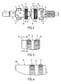
- the spline rings have a substantially trapezoidal axial cross section, as shown more particularly in FIGS. 3 and 4 .
- the flutes have a cross section of trapezoidal shape, as shown in FIG. 5 .
- FIG. 6 when a very good penetration of the grooves in the coding ring is desired, it will be adopted a cross section of triangular shape for the splines, as shown in FIG. 6 .
- the bottom of the grooves is disposed on a cylinder having a diameter R 12 greater than the minimum diameter R 10 of the shoulder 10 at, in particular, the surface 13.
- each of the optical coding rings 8 is produced in a material having a hardness lower than that of the steel constituting the transmission shafts 2 , 3 and, preferably, a malleable material, such as, for example but not exclusively, in German silver.
- the rings 8 are each made to have a generally cylindrical shape to comprise, on the one hand, the outer peripheral surface 8 and, on the other hand, an axial bore 15 of shape substantially similar to that of the scope and having a inner diameter R 15 smaller than the largest diameter R 11 of the span including the flute ring 11.
- the axial bore 15 is made to include an inner shoulder 16 which has a diameter R 16 smaller than the inside diameter R 15 of the axial bore 15 and, preferably, less than or equal to the smallest diameter R 10 of the span. 10 including the spline ring 11. in the example shown, the inner diameter of the bore of the shoulder 16 is equal to the clearance, to the smaller diameter R 10 of the scope 10.
- each coding ring 6 on its respective transmission shaft 2, 3 is then done by broaching, that is to say by engagement of the ring 6 on the bearing 10 in the direction of the arrow f 1 , so as to engage the splines of the rings 11 in the wall of the bore 15 towards the inner shoulder 16 , without however engaging the grooves 12 in the shoulder.
- broaching that is to say by engagement of the ring 6 on the bearing 10 in the direction of the arrow f 1 , so as to engage the splines of the rings 11 in the wall of the bore 15 towards the inner shoulder 16 , without however engaging the grooves 12 in the shoulder.
- the possible chips of the material constituting the ring 6 will then be forced back in the opposite direction to that F 1 introduction and therefore towards the shoulder 16 and thus remain prisoners.
- the coding ring 6 thus adapted is rolled onto the transmission shaft 2 , 3 at a surface of the ring 6 situated at the opposite the shoulder 16 relative to at least one of the flute rings 11 and according to the example shown at the surface facing the smooth surface 13 between the two rings 11 .
- the rolling thus carried out contributes to immobilizing the optical ring in axial translation, thereby guaranteeing the integrity of the ring over time.
- the broaching of the ring 6 and its rolling can be carried out at any stage of the manufacture of the gauge 1 . However, preferably, the rolling occurs after assembly of the two transmission shafts together through the torsion bar 4 .
- the manufacturing or machining of the optical coding means on the surface 8 may take place at any stage and preferably after assembly of the axes and pinning and crimping of the rings, so as to guarantee perfect correspondence optical marks arranged in the surfaces 8 when no torque is applied to the transmission shafts 2, 3.
- each reception range of a coding ring could have only one ring of grooves that would not necessarily be made in relief.
- it could be envisaged to make the grooves 12 over the entire axial length of the bearing 10 and the rolling would occur on the edge of the ring opposite the shoulder 16 , so as to perform a crimping of the ring on the reach 10 .
- the coding rings 6 and the transmission pins 2 , 3 are implemented in the context of a torsion gauge 1, however, the invention could be implemented for any type of transmission.
- transmission shafts such as for example a transmission shaft of a rotating machine such as an electric motor or a generator, a turbine or the like requiring the implementation of optical coding means for detecting the angular position of the shaft and / or the angular speed of the drive shaft.
Abstract
Description
La présente invention concerne le domaine technique des systèmes utilisés pour repérer la position d'un mobile animé d'un mouvement de rotation.The present invention relates to the technical field of the systems used to locate the position of a mobile animated with a rotational movement.
L'invention concerne plus particulièrement les systèmes assurant un repérage de la position d'un arbre de transmission destiné à assurer l'entraínement en rotation d'un système mécanique pour réaliser ce qu'il est convenu d'appeler un entraínement de puissance.The invention relates more particularly to systems providing a tracking the position of a transmission shaft intended to ensure the rotational drive a mechanical system to achieve what is known as a training power.
L'invention concerne également des arbres destinés à transmettre un ordre ou une commande à un système mécanique tel que par exemple un arbre de transmission utilisé pour transmettre l'information, émise à partir d'un volant d'un véhicule automobile, à la direction de ce même véhicule.The invention also relates to trees for transmitting an order or a control to a mechanical system such as for example a transmission shaft used to transmit information, emitted from a steering wheel of a vehicle automobile, to the management of the same vehicle.
Dans le cadre d'une telle application par exemple, il est nécessaire de pouvoir détecter la position et l'effort exercé sur l'arbre de transmission afin de pouvoir procéder à l'assistance du mouvement et donc de la direction.In the context of such an application for example, it is necessary to detect the position and the force exerted on the drive shaft in order to be able to proceed with the assistance of the movement and therefore of the direction.
A cet effet, il est connu de mettre en oeuvre une jauge de torsion comprenant deux arbres de transmission qui sont mobiles en rotation l'un par rapport à l'autre et lié en rotation par une barre de torsion. Il est alors nécessaire de connaítre la position de chaque arbre constitutif de la jauge de torsion tant de manière absolue que relative. En effet, la différence de position angulaire des arbres est fonction du couple de torsion appliqué à l'arbre de transmission.For this purpose, it is known to implement a torsion gauge comprising two transmission shafts which are rotatable relative to one another and linked in rotation by a torsion bar. It is then necessary to know the position of each constituent shaft of the torsion gauge so absolutely relative. In fact, the difference in the angular position of the shafts depends on the torque torsion applied to the drive shaft.
Afin d'effectuer un tel repérage angulaire de chaque arbre de transmission, il a été développé une technique consistant à associer chaque arbre de transmission à des moyens de codage optiques qui permettent, avec un système de lecture adapté, de repérer leur position. Les moyens de codage optique se présentent sous la forme d'une surface optique sensiblement cylindrique usinée directement dans la masse des arbres de transmission.In order to perform such an angular registration of each transmission shaft, it has has been developed a technique of associating each transmission shaft with optical coding means which make it possible, with a suitable reading system, to locate their position. The optical coding means are in the form of a substantially cylindrical optical surface machined directly into the mass of transmission shafts.
Un tel mode de réalisation a permis de démontrer la faisabilité du procédé de détection optique de la position des arbres de transmission de la jauge de torsion mais présente l'inconvénient d'être particulièrement onéreux et donc inadapté à une production en grande série.Such an embodiment made it possible to demonstrate the feasibility of the method of optical detection of the position of the transmission shafts of the torsion gauge but has the disadvantage of being particularly expensive and therefore unsuitable for mass production.
Ainsi, il est apparu le besoin d'un nouveau type d'arbre de transmission à codage optique et d'un procédé de fabrication qui permette de remplir les exigences de grande précision de réalisation notamment de la surface optique utilisée pour la détection de position tout en présentant un moindre coût de fabrication permettant de réaliser des jauges de torsion à un coût acceptable pour l'industrie automobile notamment.Thus, it appeared the need for a new type of drive shaft to optical coding and a manufacturing process that meets the requirements high accuracy of realization including the optical surface used for the position detection while having a lower manufacturing cost making it possible to make torsion gauges at an acceptable cost for the automotive industry especially.
Afin d'atteindre ces objectifs, l'invention concerne un procédé de fabrication d'un arbre de transmission équipé d'une bague de codage optique comprenant les étapes suivantes :
- fabrication de l'arbre de transmission, de manière qu'il comprenne une portée de réception de la bague, présentant au moins un anneau de cannelures de direction axiale,
- fabrication de la bague de codage, de manière qu'elle comprenne, d'une part, au moins une surface extérieure périphérique pour le codage optique et, d'autre part, un alésage axial de forme sensiblement analogue à celle de la portée présentant un diamètre intérieur inférieur au plus grand diamètre de la portée, y compris l'anneau de cannelures, et comprenant un épaulement intérieur qui présente un diamètre inférieur au diamètre intérieur de l'alésage axial,
- brochage de la bague de codage sur l'arbre au niveau de la portée de réception, de manière à engager les cannelures dans la paroi de l'alésage vers l'épaulement intérieur, sans engager les cannelures dans l'épaulement,
- et sertissage par roulage de la bague de codage au niveau d'une surface de la bague située à l'opposé de l'épaulement par rapport à l'anneau de cannelure.
- manufacture of the transmission shaft, so that it comprises a receiving range of the ring, having at least one ring of axial direction splines,
- manufacturing of the coding ring, so that it comprises, on the one hand, at least one peripheral outer surface for optical coding and, on the other hand, an axial bore of a shape substantially similar to that of the span having a inner diameter less than the largest diameter of the span, including the spline ring, and comprising an inner shoulder which has a diameter smaller than the inside diameter of the axial bore,
- pinning the coding ring on the shaft at the receiving surface, so as to engage the grooves in the wall of the bore towards the inner shoulder, without engaging the grooves in the shoulder,
- and crimping by rolling the coding ring at a surface of the ring located opposite the shoulder relative to the spline ring.
L'association du brochage et du roulage de la bague de codage à l'opposé de l'épaulement par rapport à l'anneau de cannelure permet de manière fort avantageuse d'emprisonner les éventuels copeaux du matériau constitutif de la bague de codage susceptibles de se former lors du brochage. Cet emprisonnement permet alors de garantir la parfaite propreté de l'arbre de transmission obtenu en réduisant au maximum les risques de pollution voir d'endommagement de la surface extérieure cylindrique pour le codage optique de la bague.The combination of pinning and rolling of the coding ring as opposed to the shoulder relative to the spline ring provides a very advantageous way to trap any chips of the material constituting the coding ring likely to form during broaching. This imprisonment then allows guarantee the perfect cleanliness of the drive shaft obtained by reducing the maximum the risks of pollution see of damage of the external surface cylindrical for the optical coding of the ring.
Selon l'invention l'anneau de cannelures peut être réalisé de différentes façons. According to the invention the ring of flutes can be realized in different ways.
Selon une caractéristique de l'invention, l'anneau de cannelures est aménagé en relief par rapport à la portée de réception de la bague. Le diamètre de l'anneau de cannelures au niveau du fond de cannelures est alors de préférence mais non nécessairement supérieur au diamètre de la portée.According to one characteristic of the invention, the spline ring is arranged raised in relation to the reception range of the ring. The diameter of the ring of splines at the bottom of grooves is then preferably but not necessarily greater than the diameter of the span.
Différentes formes peuvent être adoptées pour l'anneau de cannelures. Ainsi selon une caractéristique de l'invention l'anneau de cannelures présente, en section droite axiale, une forme trapézoïdale ou rectangulaire.Different shapes can be adopted for the flute ring. So according to a characteristic of the invention the ring of grooves present, in section axial right, a trapezoidal or rectangular shape.
Selon une autre caractéristique de l'invention, les cannelures présentent, en section droite transversale, une forme trapézoïdale ou triangulaire, que l'anneau de cannelures soit réalisé en relief ou non.According to another characteristic of the invention, the grooves have, in cross section, a trapezoidal or triangular shape, that the ring of grooves is made in relief or not.
Selon l'invention, l'arbre de transmission présente au moins un anneau de cannelures et peut donc en comporter plusieurs.According to the invention, the transmission shaft has at least one ring of grooves and can therefore include several.
Ainsi, selon une caractéristique de l'invention, la fabrication de l'arbre de transmission est effectuée de manière que la portée de réception de la bague présente au moins deux anneaux de cannelures distants axialement l'un de l'autre.Thus, according to one characteristic of the invention, the manufacture of the transmission is carried out so that the reception range of the ring presents at least two rings of grooves spaced apart axially from one another.
De manière préférée mais non strictement nécessaire, le roulage de la bague de codage est alors effectué au niveau de la surface de la bague située en regard de la surface de la portée qui est située entre les deux anneaux de cannelures de manière à sertir la matière de la bague de codage entre les deux anneaux de cannelures.In a preferred but not strictly necessary manner, the rolling of the ring of encoding is then performed at the surface of the ring located next to the reach surface which is located between the two spline rings so as to Crimp the material of the coding ring between the two spline rings.
Cette disposition avantageuse de l'invention permet alors de renforcer l'immobilisation axiale de la bague de codage optique sur l'arbre de transmission.This advantageous arrangement of the invention makes it possible to reinforce the axial immobilization of the optical coding ring on the transmission shaft.
Selon l'invention, l'arbre de transmission et sa bague de codage peuvent être réalisés en tout matériau approprié. Selon une caractéristique préférée mais non strictement nécessaire de l'invention l'arbre de transmission est réalisé en acier et la bague de codage est réalisée dans un métal ou un alliage métallique présentant une dureté inférieure à celle de l'arbre de transmission. De manière préférée, la bague de codage est réalisée en maillechort, à savoir un alliage de cuivre, de nickel et de zinc, avec ou sans autre élément d'alliage.According to the invention, the transmission shaft and its coding ring can be made of any suitable material. According to a preferred characteristic but not strictly necessary of the invention the transmission shaft is made of steel and the encoder ring is made of a metal or a metal alloy having a hardness lower than that of the drive shaft. Preferably, the ring of encoding is made in German silver, namely an alloy of copper, nickel and zinc, with or without other alloying element.
Selon l'invention, l'usinage de la surface extérieure pour y réaliser les moyens de codage optique peut être effectué avant ou après le brochage et le roulage de ladite bague. Toutefois, de manière préférée, la surface optique de la bague de codage est usinée et réalisée après brochage et sertissage de ladite bague sur l'arbre de transmission. Ce mode de fabrication est particulièrement favorisé par les avantages techniques du procédé de fabrication conforme à l'invention dans la mesure où le brochage et le sertissage de la bague se fait sans dégagement de copeaux ou de particules polluantes.According to the invention, the machining of the outer surface to achieve the means optical coding can be performed before or after the pinning and rolling of said Ring. However, preferably, the optical surface of the coding ring is machined and performed after broaching and crimping said ring on the shaft of transmission. This mode of manufacture is particularly favored by the advantages techniques of the manufacturing method according to the invention insofar as the broaching and crimping the ring is done without release of chips or polluting particles.
Dans une application préférée mais non limitative, le procédé selon l'invention est mis en oeuvre pour réaliser une jauge de torsion comprenant deux arbres de transmission équipés chacun d'une bague de codage optique, mobiles l'un par rapport à l'autre en rotation axiale, en étant liés en rotation par une barre de torsion. Cette fabrication est alors réalisée en deux étapes :
- fabrication de chacun des arbres de transmission conformément au procédé de fabrication selon l'invention décrit précédemment,
- et assemblage des arbres de transmission ensemble et avec la barre de torsion.
- manufacturing each of the transmission shafts according to the manufacturing method according to the invention described above,
- and assembly of the transmission shafts together and with the torsion bar.
De manière préférée, le brochage et le sertissage par roulage des bagues optiques sur leur arbre respectif sont réalisés avant l'assemblage des arbres entre eux, par l'intermédiaire de la barre de torsion.Preferably, the broaching and crimping by rolling rings on their respective shafts are made before assembling the shafts together, via the torsion bar.
L'usinage des deux zones de réflexion (miroir) des deux bagues optiques est réalisé après l'assemblage des deux arbres, de façon à assurer une coaxialité parfaite des deux surfaces de réflexion.The machining of the two reflection zones (mirror) of the two optical rings is realized after the assembly of the two trees, so as to ensure perfect coaxiality two reflection surfaces.
L'invention concerne également un arbre de transmission caractérisé en ce qu'il comprend, au moins, une bague de codage optique rapportée.The invention also relates to a transmission shaft characterized in that it includes, at least, an optical coding ring reported.
L'invention concerne, également, une jauge de torsion comprenant deux arbres de transmission, chacun mobile en rotation l'un par rapport à l'autre, en étant liés en rotation par une barre de torsion caractérisée en ce que chaque arbre de transmission est équipé d'une bague de codage optique rapportée.The invention also relates to a torsion gauge comprising two shafts each movable in rotation relative to one another, being connected in rotation by a torsion bar characterized in that each transmission shaft is equipped with a reported optical coding ring.
Selon une caractéristique préférée, mais non strictement nécessaire de l'invention, les deux bagues de codage optique de chacun des arbres de transmission constitutifs de la jauge de torsion sont disposés de manière adjacente.According to a preferred but not strictly necessary characteristic of the invention, the two optical coding rings of each of the transmission shafts constituent parts of the torsion gauge are arranged adjacent to each other.
Selon une caractéristique de l'invention, la bague de codage optique est brochée et sertie par roulage sur son arbre de transmission, au niveau d'une portée de réception de la bague. Bien entendu, un autre mode de montage et d'assemblage de la bague sur l'arbre pourrait être envisagé.According to one characteristic of the invention, the optical coding ring is stitched and crimped by rolling on its drive shaft, at a range of receiving the ring. Of course, another way of assembling and assembling the ring on the tree could be considered.
Diverses autres caractéristiques de l'invention ressortent de la description ci-dessous
effectuée en relation avec les dessins annexés qui illustrent un exemple, non
limitatif, de réalisation d'une jauge de torsion comprenant deux arbres de
transmission selon l'invention.
L'invention propose un nouveau procédé de fabrication d'un arbre de transmission équipé d'une bague de codage optique tel que susceptible d'être mis en oeuvre, par exemple mais non nécessairement, dans le cadre d'une jauge de torsion comme plus particulièrement illustrée à la fig. 1 et désignée dans son ensemble par la référence 1.The invention proposes a novel method for manufacturing a transmission shaft equipped with an optical coding ring such as that which may be implemented, for example but not necessarily, in the context of a torsion gauge such as particularly illustrated in FIG. 1 and referred to as a whole by reference 1.
Ainsi, la jauge de torsion 1 comprend deux arbres de transmission 2 et 3 d'axe
Δ. Les arbres de transmission 2 et 3 sont mobiles l'un par rapport à l'autre en rotation
d'axe Δ et sont reliés par une barre de torsion 4, de sorte que les deux arbres de
transmission 2 et 3 sont liés l'un à l'autre en translation d'axe Δ et sont susceptibles
de connaítre un mouvement relatif de rotation autour de l'axe Δ selon l'intensité du
couple appliqué à chacun des deux axes de transmission 2, 3. Comme le montre la
fig. 1, la barre de torsion 4 se trouve disposée, à cet effet, dans un alésage axial 5 de
l'arbre de transmission 2, de manière à être liée par chacune de ses deux extrémités à
l'un des arbres de transmission 2 et 3. Il s'agit ici d'un mode de réalisation d'une
jauge de torsion bien connue de l'homme du métier et ne nécessitant donc pas de
plus amples explications.Thus, the torsion gauge 1 comprises two
Conformément à une caractéristique essentielle de l'invention et afin de
permettre une détection optique de la position angulaire de la jauge 1 ainsi que de la
position angulaire relative des deux arbres de transmission 2 et 3, ces derniers sont
chacun équipé d'une bague de codage optique 6. Selon l'exemple illustré les bagues
de codage optique 6 sont disposées de manière adjacente. Chaque bague de codage
optique 6 présente alors une surface extérieure périphérique 8 pour le codage
optique. La géométrie particulière de chaque surface extérieure périphérique 8 ne
rentre pas dans le cadre de la présente invention. Tout au plus il convient de préciser
que chaque surface extérieure périphérique 8 présente une forme générale
cylindrique et se trouve réalisée de manière à présenter une ou plusieurs séries de
repères optiques susceptibles d'être détectés par des moyens non représentés
permettant à la fois de connaítre la position angulaire de la jauge de torsion 1 dans
son ensemble ainsi que l'éventuel écart angulaire entre les deux arbres de
transmission 2 et 3. Afin d'offrir une résolution satisfaisante, les surfaces
périphériques pour le codage optique 8 doivent être réalisées avec une très grande
précision et présenter un très fort indice de réflexion.According to an essential characteristic of the invention and in order to allow an optical detection of the angular position of the gauge 1 as well as the relative angular position of the two
Compte tenu de la dureté des matériaux constitutifs des arbres de transmission
2, la réalisation des surfaces de codage optique directement dans le matériau
constitutif de ces derniers présenterait un coût de réalisation rédhibitoire pour une
production en grande série. Ainsi, l'invention propose de rapporter les bagues de
codage optique 6 sur les arbres de transmission 2 et 3.Given the hardness of the constituent materials of the
Les bagues de codage 6 peuvent alors être réalisées dans un matériau plus
malléable que les arbres de transmission 2 et donc présenter des coûts d'usinage
moindres.The coding rings 6 can then be made of a more malleable material than the
L'invention propose donc de fabriquer chaque arbre de transmission 2, 3, de
manière qu'il comprenne une portée 10 de réception de la bague de codage 6.
Conformément à une caractéristique essentielle de l'invention, chaque portée de
réception 10 comprend alors au moins un et selon l'exemple illustré deux anneaux 11
de cannelures 12 de direction axiale Δ.The invention therefore proposes to manufacture each
Comme le montrent plus particulièrement les fig. 3 et 4 et selon l'exemple
illustré, les deux anneaux de cannelures 11 sont aménagés en relief par rapport à la
portée 10 et sont distants axialement l'un de l'autre, de manière que la portée 10
présente une surface lisse 13 entre les anneaux 11. Chaque surface 13 définit, comme
cela ressortira de la suite, une gorge d'immobilisation axiale de la bague de codage
correspondante.As shown more particularly in FIGS. 3 and 4 and according to the illustrated example, the two rings of
Selon l'exemple illustré, les anneaux de cannelures présentent une section droite axiale sensiblement trapézoïdale, comme le montrent plus particulièrement les fig. 3 et 4. De même, selon la forme de réalisation illustrée, les cannelures présentent une section droite transversale de forme trapézoïdale, comme le montre la fig. 5. Cependant, lorsqu'une très bonne pénétration des cannelures dans la bague de codage est recherchée, il sera adopté une section droite transversale de forme triangulaire pour les cannelures, comme illustré à la fig. 6.According to the illustrated example, the spline rings have a substantially trapezoidal axial cross section, as shown more particularly in FIGS. 3 and 4 . Likewise, according to the illustrated embodiment, the flutes have a cross section of trapezoidal shape, as shown in FIG. 5 . However, when a very good penetration of the grooves in the coding ring is desired, it will be adopted a cross section of triangular shape for the splines, as shown in FIG. 6 .
De plus, selon l'exemple illustré, le fond des cannelures est disposé sur un
cylindre présentant un diamètre R12 supérieur au diamètre minimum R10 de
l'épaulement 10 au niveau, notamment, de la surface 13. In addition, according to the illustrated example, the bottom of the grooves is disposed on a cylinder having a diameter R 12 greater than the minimum diameter R 10 of the
Indépendamment de la fabrication de chaque arbre de transmission 2, 3, il est
procédé à la fabrication de chacune des bagues de codage optique 8 dans un matériau
présentant une dureté inférieure à celle de l'acier constitutif des arbres de
transmission 2, 3 et, de préférence, un matériau malléable, tel que, par exemple mais
non exclusivement, en maillechort. Les bagues 8 sont chacune réalisées de manière à
présenter une forme générale cylindrique pour comprendre, d'une part, la surface
extérieure périphérique 8 et, d'autre part, un alésage axial 15 de forme sensiblement
analogue à celle de la portée et présentant un diamètre intérieur R15 inférieur au plus
grand diamètre R11 de la portée y compris l'anneau de cannelure 11. Independently of the manufacture of each
L'alésage axial 15 est réalisé de manière à comprendre un épaulement intérieur
16 qui présente un diamètre R16 inférieur au diamètre intérieur R15 de l'alésage axial
15 et, de préférence, inférieur ou égal au plus petit diamètre R10 de la portée 10 y
compris l'anneau de cannelure 11. Selon l'exemple illustré, le diamètre intérieur de
l'alésage de l'épaulement 16 est égal au jeu près au plus petit diamètre R10 de la
portée 10. The
L'assemblage de chaque bague de codage 6 sur son arbre de transmission
respectif 2, 3 se fait alors ensuite par brochage, c'est-à-dire par engagement de la
bague 6 sur la portée 10 dans le sens de la flèche f1, de manière à engager les
cannelures des anneaux 11 dans la paroi de l'alésage 15 vers l'épaulement intérieur
16, sans toutefois engager les cannelures 12 dans l'épaulement. Au cours de cet
engagement, les éventuels copeaux de la matière constitutive de la bague 6 seront
alors refoulés en sens inverse de celui F1 d'introduction et donc en direction de
l'épaulement 16 et ainsi restent prisonniers.The assembly of each
Après ce brochage, conformément à une autre caractéristique de l'invention, il
est procédé au roulage de la bague de codage 6 ainsi adapté sur l'arbre de
transmission 2, 3 au niveau d'une surface de la bague 6 située à l'opposé de
l'épaulement 16 par rapport à l'un au moins des anneaux de cannelure 11 et selon
l'exemple illustré au niveau de la surface située en regard de la surface lisse 13 entre
les deux anneaux 11. Le roulage ainsi effectué contribue à immobiliser la bague
optique en translation axiale, garantissant ainsi l'intégrité de la bague dans le temps.
Selon l'invention, le brochage de la bague 6 et son roulage peuvent être effectués à
tout stade de la fabrication de la jauge 1. Toutefois de manière préférée, le roulage
intervient après assemblage des deux arbres de transmission entre eux par
l'intermédiaire de la barre de torsion 4.After this broaching, according to another characteristic of the invention, the
De plus, conformément à l'invention, la fabrication ou l'usinage des moyens de
codage optique sur la surface 8 peut intervenir à tout stade et de préférence après
assemblage des axes et brochage et sertissage des bagues, de manière à garantir la
parfaite correspondance des repères optiques aménagés dans les surfaces 8 lorsque
aucun couple n'est appliqué aux arbres de transmission 2, 3. In addition, according to the invention, the manufacturing or machining of the optical coding means on the
Selon l'exemple décrit précédemment et illustré aux fig. 1 à 5 les portées de
réception des anneaux de codage sont pourvues de deux anneaux de cannelures
réalisés en relief. Toutefois, conformément à l'invention, chaque portée de réception
d'une bague de codage ne pourrait présenter qu'un seul anneau de cannelures qui ne
serait pas nécessairement réalisé en relief. Ainsi, il pourrait être envisagé de réaliser
les cannelures 12 sur toute la longueur axiale de la portée 10 et le roulage
interviendrait sur le bord de la bague à l'opposé de l'épaulement 16, de manière à
réaliser un sertissage de la bague sur la portée 10.According to the example described above and illustrated in FIGS. 1 to 5 the reception surfaces of the coding rings are provided with two rings of grooves made in relief. However, according to the invention, each reception range of a coding ring could have only one ring of grooves that would not necessarily be made in relief. Thus, it could be envisaged to make the
Par ailleurs, selon l'invention, les bagues de codage 6 et les axes de transmission 2, 3 sont mis en oeuvre dans le cadre d'une jauge de torsion 1 toutefois, l'invention pourrait être mise en oeuvre pour tout type d'arbres de transmission tel que par exemple un arbre de transmission d'une machine tournante comme un moteur électrique ou encore une génératrice, une turbine ou analogue nécessitant la mise en oeuvre de moyens de codage optique permettant de détecter la position angulaire de l'arbre et/ou la vitesse angulaire de l'arbre de transmission.Furthermore, according to the invention, the coding rings 6 and the transmission pins 2 , 3 are implemented in the context of a torsion gauge 1, however, the invention could be implemented for any type of transmission. transmission shafts such as for example a transmission shaft of a rotating machine such as an electric motor or a generator, a turbine or the like requiring the implementation of optical coding means for detecting the angular position of the shaft and / or the angular speed of the drive shaft.
Bien entendu, diverses autres modifications peuvent être apportées à l'invention sans sortir de son cadre.Of course, various other modifications can be made to invention without departing from its scope.
Claims (18)
Applications Claiming Priority (2)
| Application Number | Priority Date | Filing Date | Title |
|---|---|---|---|
| FR0310245A FR2859123B1 (en) | 2003-08-28 | 2003-08-28 | TREE EQUIPPED WITH AN OPTICAL RING AND METHOD FOR MANUFACTURING THE TREE |
| FR0310245 | 2003-08-28 |
Publications (1)
| Publication Number | Publication Date |
|---|---|
| EP1510284A1 true EP1510284A1 (en) | 2005-03-02 |
Family
ID=34089865
Family Applications (1)
| Application Number | Title | Priority Date | Filing Date |
|---|---|---|---|
| EP04356145A Withdrawn EP1510284A1 (en) | 2003-08-28 | 2004-08-23 | Shaft with an optical code ring and method for its manufacture |
Country Status (6)
| Country | Link |
|---|---|
| US (1) | US20050060870A1 (en) |
| EP (1) | EP1510284A1 (en) |
| JP (1) | JP2005076887A (en) |
| CN (1) | CN1598336A (en) |
| BR (1) | BRPI0403521A (en) |
| FR (1) | FR2859123B1 (en) |
Cited By (1)
| Publication number | Priority date | Publication date | Assignee | Title |
|---|---|---|---|---|
| DE102006057022A1 (en) * | 2006-12-04 | 2008-06-05 | Robert Bosch Gmbh | Sleeve fastening method for torque sensor, involves forming stamped indentation as part of negative contour on input and output shafts, and pressing sleeve into negative contour for locking |
Families Citing this family (3)
| Publication number | Priority date | Publication date | Assignee | Title |
|---|---|---|---|---|
| WO2015157139A1 (en) * | 2014-04-07 | 2015-10-15 | Mcgard Llc | Connection joint with broach-formed integral chip retainer |
| FR3050493B1 (en) * | 2016-04-26 | 2018-05-25 | Foundation Brakes France Sas | LOW-COST NUT FOR VEHICLE BRAKING SYSTEM |
| CN106589723B (en) * | 2016-11-29 | 2020-08-21 | 张家口洁源环保塑胶有限公司 | A essence filtration equipment for filtering feed liquid of medium temperature water-soluble membrane |
Citations (7)
| Publication number | Priority date | Publication date | Assignee | Title |
|---|---|---|---|---|
| DE19853798C1 (en) * | 1998-11-21 | 2000-09-21 | Bayerische Motoren Werke Ag | Connection between two shafts is a sleeve pushed over the teeth or splines at the shaft ends in a press fit with malleable distortion to mold round the teeth/splines in a keyed and positive fit |
| EP1046893A2 (en) * | 1999-04-23 | 2000-10-25 | Trw Inc. | Torque sensing apparatus and method |
| WO2001022038A1 (en) * | 1999-09-21 | 2001-03-29 | Delphi Technologies, Inc. | High resolution optical encoder |
| US20010011698A1 (en) * | 1999-12-22 | 2001-08-09 | Pwb- Ruhlatec Industrieprodukte Gmbh | Angular position sensor unit |
| US6450044B1 (en) * | 1997-08-15 | 2002-09-17 | Bishop Innovation Limited | Torque transducer |
| DE10120580A1 (en) * | 2001-04-26 | 2002-11-07 | Siemens Ag | Sensor for measuring the torque applied the shaft of a motor vehicle gear box comprises two outer sleeve type pipe elements attached to the shaft so that their adjacent ends rotate relative to each other |
| DE10140616A1 (en) * | 2001-08-18 | 2003-03-06 | Bosch Gmbh Robert | Method and device for optical measurement data acquisition |
-
2003
- 2003-08-28 FR FR0310245A patent/FR2859123B1/en not_active Expired - Fee Related
-
2004
- 2004-08-23 EP EP04356145A patent/EP1510284A1/en not_active Withdrawn
- 2004-08-25 US US10/924,948 patent/US20050060870A1/en not_active Abandoned
- 2004-08-25 BR BR0403521-6A patent/BRPI0403521A/en not_active Application Discontinuation
- 2004-08-26 CN CNA2004100572628A patent/CN1598336A/en active Pending
- 2004-08-27 JP JP2004248458A patent/JP2005076887A/en active Pending
Patent Citations (7)
| Publication number | Priority date | Publication date | Assignee | Title |
|---|---|---|---|---|
| US6450044B1 (en) * | 1997-08-15 | 2002-09-17 | Bishop Innovation Limited | Torque transducer |
| DE19853798C1 (en) * | 1998-11-21 | 2000-09-21 | Bayerische Motoren Werke Ag | Connection between two shafts is a sleeve pushed over the teeth or splines at the shaft ends in a press fit with malleable distortion to mold round the teeth/splines in a keyed and positive fit |
| EP1046893A2 (en) * | 1999-04-23 | 2000-10-25 | Trw Inc. | Torque sensing apparatus and method |
| WO2001022038A1 (en) * | 1999-09-21 | 2001-03-29 | Delphi Technologies, Inc. | High resolution optical encoder |
| US20010011698A1 (en) * | 1999-12-22 | 2001-08-09 | Pwb- Ruhlatec Industrieprodukte Gmbh | Angular position sensor unit |
| DE10120580A1 (en) * | 2001-04-26 | 2002-11-07 | Siemens Ag | Sensor for measuring the torque applied the shaft of a motor vehicle gear box comprises two outer sleeve type pipe elements attached to the shaft so that their adjacent ends rotate relative to each other |
| DE10140616A1 (en) * | 2001-08-18 | 2003-03-06 | Bosch Gmbh Robert | Method and device for optical measurement data acquisition |
Cited By (2)
| Publication number | Priority date | Publication date | Assignee | Title |
|---|---|---|---|---|
| DE102006057022A1 (en) * | 2006-12-04 | 2008-06-05 | Robert Bosch Gmbh | Sleeve fastening method for torque sensor, involves forming stamped indentation as part of negative contour on input and output shafts, and pressing sleeve into negative contour for locking |
| WO2008068095A1 (en) * | 2006-12-04 | 2008-06-12 | Robert Bosch Gmbh | Method for fastening a sleeve on a shaft |
Also Published As
| Publication number | Publication date |
|---|---|
| JP2005076887A (en) | 2005-03-24 |
| US20050060870A1 (en) | 2005-03-24 |
| CN1598336A (en) | 2005-03-23 |
| FR2859123B1 (en) | 2006-12-01 |
| BRPI0403521A (en) | 2005-06-07 |
| FR2859123A1 (en) | 2005-03-04 |
Similar Documents
| Publication | Publication Date | Title |
|---|---|---|
| EP0148794B1 (en) | Angular-position adjuster of a rotary driving part coupled to a rotary driven part | |
| FR2851521A1 (en) | Double enveloping worm gear for vehicle seat adjusting device, has worm nut supported by bearing with external surface axially shifted with respect to nut teeth, and thrust washer surrounding external surface of bearing | |
| FR2640010A1 (en) | ARRANGEMENT FOR FIXING A HIGH-HARDNESS BEARING RING INTO THE LOWEST HARDNESS OF A HOUSING OF A HOUSING OR ON THE LOWEST HARDNESS SURFACE OF A SHAFT OR THE LIKE | |
| FR2728816A1 (en) | Forked shaft manufacturing procedure | |
| FR2661227A1 (en) | Method for producing a shaft, particularly a cardan shaft, formed from an assembly of a tube made from fibre-reinforced synthetic material and a connection element made from rigid material | |
| EP1523630A2 (en) | Mechanical actuator including a helical-cam nut | |
| EP1510284A1 (en) | Shaft with an optical code ring and method for its manufacture | |
| FR3069608B1 (en) | SYSTEM FOR CONTROLLING A PARKING LOCK TO BLOCK A TRANSMISSION OF A MOTOR VEHICLE | |
| EP0195474A2 (en) | Flanged bush bearing and its manufacturing process | |
| FR2764842A1 (en) | INTEGRATED GUIDANCE DEVICE FOR PRINT SLEEVE OR CYLINDER AND SLEEVE OR CYLINDER EQUIPPED WITH SUCH DEVICE | |
| FR2730774A1 (en) | HOMOCINETIC JOINT WITH CENTRAL JOINT | |
| FR2857893A1 (en) | METHOD FOR MAKING A PROGRESSIVE TRANSITION RETENTION FLANGE | |
| FR3056160A1 (en) | TRANSMISSION FOR MOTOR VEHICLE WITH ELECTRIC PROPULSION | |
| FR2556427A1 (en) | Locking ring for securing boss to spindle | |
| EP2066537B1 (en) | Drive mechanism comprising means for guiding a drive shaft | |
| FR3057625B1 (en) | LAUNCHER FOR MOTOR VEHICLE STARTER WITH THERMAL MOTOR | |
| FR2751146A1 (en) | CYLINDER HEAD ARRANGEMENT FOR AN ELECTRIC MOTOR HAVING IMPROVED MECHANICAL STRENGTH | |
| FR2967201A1 (en) | System for producing dynamic seal of hydrostatic motor to be mounted on wheel shaft of vehicle, has centering ring mounting dynamic lip seal floating on support plane with respect to shaft before its attachment to support plane | |
| FR2891518A1 (en) | Car gearbox has anti-theft system mounted on drive- or driven shaft comprising ring with radial notches on its outer surface, into which lug on swiveling arm fits, preventing shaft from rotating | |
| FR2618090A1 (en) | Method of manufacturing a torsion-damper hub | |
| EP1884673B1 (en) | Coupling system and braking system | |
| FR3071888A1 (en) | MOTOR VEHICLE POWERTRAIN ASSEMBLY COMPRISING A TRANSMISSION SHAFT AND AN ANNULAR PART ATTACHED TO THE TRANSMISSION SHAFT | |
| EP3523164B1 (en) | Toothed wheel for a gear motor of a window wiper | |
| FR2816011A1 (en) | Starter, for vehicle, is fitted with pinion, which is manufactured in two parts. | |
| FR2841522A1 (en) | Motor vehicle steering column has shaft with bearing retained by radial projections made from material of shaft forced in axial direction |
Legal Events
| Date | Code | Title | Description |
|---|---|---|---|
| PUAI | Public reference made under article 153(3) epc to a published international application that has entered the european phase |
Free format text: ORIGINAL CODE: 0009012 |
|
| STAA | Information on the status of an ep patent application or granted ep patent |
Free format text: STATUS: THE APPLICATION HAS BEEN PUBLISHED |
|
| AK | Designated contracting states |
Kind code of ref document: A1 Designated state(s): AT BE BG CH CY CZ DE DK EE ES FI FR GB GR HU IE IT LI LU MC NL PL PT RO SE SI SK TR |
|
| AX | Request for extension of the european patent |
Extension state: AL HR LT LV MK |
|
| AKX | Designation fees paid | ||
| REG | Reference to a national code |
Ref country code: DE Ref legal event code: 8566 |
|
| STAA | Information on the status of an ep patent application or granted ep patent |
Free format text: STATUS: THE APPLICATION IS DEEMED TO BE WITHDRAWN |
|
| 18D | Application deemed to be withdrawn |
Effective date: 20050903 |