EP1523622B1 - Machine a pistons equipee d'un dispositif reduisant les pulsations - Google Patents
Machine a pistons equipee d'un dispositif reduisant les pulsations Download PDFInfo
- Publication number
- EP1523622B1 EP1523622B1 EP03740448A EP03740448A EP1523622B1 EP 1523622 B1 EP1523622 B1 EP 1523622B1 EP 03740448 A EP03740448 A EP 03740448A EP 03740448 A EP03740448 A EP 03740448A EP 1523622 B1 EP1523622 B1 EP 1523622B1
- Authority
- EP
- European Patent Office
- Prior art keywords
- pressure
- pressure compensation
- compensation line
- piston machine
- line
- Prior art date
- Legal status (The legal status is an assumption and is not a legal conclusion. Google has not performed a legal analysis and makes no representation as to the accuracy of the status listed.)
- Expired - Lifetime
Links
- 238000006073 displacement reaction Methods 0.000 claims 1
- 210000003734 kidney Anatomy 0.000 description 16
- 230000010349 pulsation Effects 0.000 description 11
- 230000009467 reduction Effects 0.000 description 6
- 238000010079 rubber tapping Methods 0.000 description 4
- 230000002250 progressing effect Effects 0.000 description 2
- 230000000750 progressive effect Effects 0.000 description 2
- 230000005855 radiation Effects 0.000 description 2
- 238000010408 sweeping Methods 0.000 description 2
- 230000006978 adaptation Effects 0.000 description 1
- 230000005540 biological transmission Effects 0.000 description 1
- 230000006835 compression Effects 0.000 description 1
- 238000007906 compression Methods 0.000 description 1
- 230000001419 dependent effect Effects 0.000 description 1
- 230000003292 diminished effect Effects 0.000 description 1
- 239000012530 fluid Substances 0.000 description 1
- 230000006870 function Effects 0.000 description 1
- 230000002706 hydrostatic effect Effects 0.000 description 1
- 239000000314 lubricant Substances 0.000 description 1
- 230000010363 phase shift Effects 0.000 description 1
- 230000001902 propagating effect Effects 0.000 description 1
- 238000005086 pumping Methods 0.000 description 1
Images

Classifications
-
- F—MECHANICAL ENGINEERING; LIGHTING; HEATING; WEAPONS; BLASTING
- F04—POSITIVE - DISPLACEMENT MACHINES FOR LIQUIDS; PUMPS FOR LIQUIDS OR ELASTIC FLUIDS
- F04B—POSITIVE-DISPLACEMENT MACHINES FOR LIQUIDS; PUMPS
- F04B11/00—Equalisation of pulses, e.g. by use of air vessels; Counteracting cavitation
-
- F—MECHANICAL ENGINEERING; LIGHTING; HEATING; WEAPONS; BLASTING
- F04—POSITIVE - DISPLACEMENT MACHINES FOR LIQUIDS; PUMPS FOR LIQUIDS OR ELASTIC FLUIDS
- F04B—POSITIVE-DISPLACEMENT MACHINES FOR LIQUIDS; PUMPS
- F04B1/00—Multi-cylinder machines or pumps characterised by number or arrangement of cylinders
- F04B1/12—Multi-cylinder machines or pumps characterised by number or arrangement of cylinders having cylinder axes coaxial with, or parallel or inclined to, main shaft axis
- F04B1/20—Multi-cylinder machines or pumps characterised by number or arrangement of cylinders having cylinder axes coaxial with, or parallel or inclined to, main shaft axis having rotary cylinder block
- F04B1/2014—Details or component parts
- F04B1/2042—Valves
-
- F—MECHANICAL ENGINEERING; LIGHTING; HEATING; WEAPONS; BLASTING
- F04—POSITIVE - DISPLACEMENT MACHINES FOR LIQUIDS; PUMPS FOR LIQUIDS OR ELASTIC FLUIDS
- F04B—POSITIVE-DISPLACEMENT MACHINES FOR LIQUIDS; PUMPS
- F04B11/00—Equalisation of pulses, e.g. by use of air vessels; Counteracting cavitation
- F04B11/0091—Equalisation of pulses, e.g. by use of air vessels; Counteracting cavitation using a special shape of fluid pass, e.g. throttles, ducts
Definitions
- the invention relates to a piston engine with a device for reducing flow pulsations.
- a disadvantage of the above-described reciprocating engine is that the flow pulsations, which, although only diminished, but can not be completely avoided, transferred to the control piston, and thus the control piston in turn can be excited to vibrate. This has a direct influence on the effectiveness of the pressure equalization, which is to be made possible by the variable throttle. Furthermore, it is disadvantageous that due to the movement of the control piston, which is unavoidable by the pulsation of the pressure in the Hochbuch horrniere significant wear on the Pulsationsminderungsvorraum occurs.
- the piston engine according to the invention has the advantage that only a pressure equalization line is to be provided for generating a pulsation reduction, which is arranged between a working line and an opening arranged in a Um Kunststoff Kunststoff a control mirror.
- the pressure equalization line is only to be considered that the orifice is to be provided in the working line at a location which allows a phase-correct tapping of the advancing in the working line pressure wave.
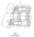
- Fig. 1 is a section through a known per se axial piston machine 1 is shown.
- a cylinder drum 2 is arranged, wherein the cylinder drum 2 is rotatably mounted with respect to a central axis 12.
- cylinder openings 3, 4 are provided, wherein the cylinder openings 3, 4 are arranged parallel to the central axis 12 and are distributed uniformly over the circumference.
- pistons 5, 6 are arranged, which are mounted displaceably in the cylinder openings 3, 4.
- the cylinder bores 3, 4 each have a cylinder opening 7, 8 at a front end of the cylinder drum 2, wherein during the rotation of the cylinder drum 2, the cylinder openings 7, 8 successively pass over a first control kidney 9 and a second control kidney 10, the control kidneys 9, 10 are arranged in a control mirror 11 which is rotatably connected to the housing of the axial piston machine 1.
- the control kidneys 9, 10, which extend along a circular segment, are each connected to a working line, not shown in FIG. 1.
- the pistons 5, 6 each have an approximately spherical extension 13, 14, whose spherical geometry corresponds to a recess 15, 16 of a sliding shoe 17, or 18, respectively.
- the sliding blocks 17, 18 are supported on a swash plate 25.
- both the spherical projections 14, 13 and the sliding blocks 17, 18 each have a pressure oil bore 21, 22 and 23, 24.
- the cylinder drum 2 For operation as an axial piston pump, the cylinder drum 2 is rotated about its central axis 12, wherein due to the inclination of the swash plate 25 with respect to the central axis 12 arranged in the cylinder drum 2 piston 5, 6 a Execute lifting movement, wherein they are connected during a suction stroke with a Niederbuch Kunststoffniere, while a Hoch réellehurois contrast with a Hochdruck horrniere.
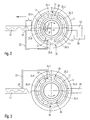
- Fig. 2 is a plan view of a control plate 11 of an axial piston pump is shown, wherein the direction of rotation of the cylinder drum 2 is indicated by an arrow.
- the cylinder drum 2 has distributed uniformly over its circumference nine cylinder bores whose cylinder openings are shown in phantom in Fig. 2 and identified by the reference numerals 35.1 to 35.9.
- a high-pressure control kidney 9 as a first control kidney
- a suction control kidney 10 as a second control kidney are arranged.
- a region is provided in each case in which the cylinder openings 35.1 to 35.9 are in contact neither with the one nor with the other control kidneys 9, 10.
- a pressure maximum in the working line 27 a pressure equalization takes place, in which the pressure in the cylinder bore, which is connected to the cylinder port 35.6, is increased via the pressure equalization line 33.
- the amplitude of the pressure wave progressing in the working line 27 is reduced in the further course. This achieves a pressure pulsation reduction.
- a maximum pressure in the working line 27 arises in each case when a cylinder opening 35.1 to 35.9 with the central axis of the working line 27 encloses a certain angle, which cyclically repeats in accordance with the number of pistons per revolution. Accordingly, at the time shown, the maximum pressure in the working line 27 from the side of the Hoch horrniere 9 has progressed by about a 1 ⁇ 4 wavelength ⁇ .
- a length L between the Hochdruck capitaniere 9 and the second end 34 of the pressure equalization line 33 which is equal to 1 ⁇ 4 ⁇ .
- the wavelength ⁇ results from the frequency of the pulsations, which in turn can be determined from the number of cylinder bores and the rotational speed of the cylinder drum 2.
- a connecting channel 39 opens into the Um Kunststoff Scheme 31, the second end of which opens into the control kidney 10.
- a corresponding device for an axial piston machine 2 is shown, which is operated as a hydraulic motor. Via the working line 28, a high pressure, which is generated for example by the axial piston machine shown in FIG. 2, fed to the hydraulic motor. The direction of rotation is counterclockwise, as indicated by the arrow.
- the Um Kunststoffs 31 When sweeping the Um Kunststoffs 31 through the cylinder openings 35.1 to 35.9 of the high pressure generated by the filling on the high pressure side in the cylinder bore via the pressure equalization line 33 is partially relaxed in the working line 27.
- the second end 34 of the pressure equalization line 33 is connected to the working line 27, that at the time at which the cylinder opening 35.1 comes into contact with the opening at the first end 32 of the pressure equalization line 33, at the second end 34 of the pressure equalization line 33, a pressure minimum prevails.
- a pilot control notch 40 is formed for a slow pressure build-up in the direction of rotation in front of the control kidneys 10.
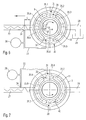
- Fig. 4 the axial piston machine 2 of Fig. 2 is shown again for a later time.
- the pressure wave, which propagates in the working line 27, according to the rotational angle of the cylinder drum 2 has advanced by 3 ⁇ 4 ⁇ , and accordingly at the end of the working line 27, which is oriented to the high-pressure control kidney, there is a pressure maximum, which is through to the cylinder opening 35.8 belonging piston is caused.
- This at the beginning of the working line 27 resulting pressure maximum moves at the speed of sound along the working line 27, where it must be reached at the second end 34 of the pressure equalization line 33 at the time to which the next rotational direction in the cylinder opening 35.5 in register with the opening at the first End 32 of the pressure equalization line 33 has arrived.
- Fig. 5 the corresponding case for the axial piston machine of Fig. 3 is shown for a later time.
- the remaining angle ⁇ which the cylinder with the cylinder opening 35.2 has to travel to the opening at the first end 32 of the pressure equalization line 33, is to be used.
- the minimum distance between the orifice at the second end 34 of the pressure equalizing line and the Auslenfinniere 9 of the axial piston machine 1 is therefore determined from the quotient of the remaining angle ⁇ and the intermediate angle ⁇ between two consecutive cylinder openings 35.2 and 35.3, in contrast, because of the tap of the pressure minimum to the case described above for a pump, a shift by ⁇ / 2 is to be considered.
- a pressure fluctuation propagating in the working line 27 also has a transit time along the pressure equalization line 33. It is necessary to take into account a changed phase position by taking into account the phase shift along the pressure equalization line as a change in length of the length L.
- FIGS. 6 and 7 show two further exemplary embodiments of pulsation reductions according to the invention, wherein a memory element 38 is provided in each case in addition to the pulsation reduction already carried out by a phase-correct tapping of a pressure fluctuation in the working line 27. With the aid of the memory element 38, it is additionally possible to increase the operating range in which the Pulsationsminderung is effective.
- a defined cross-sectional area may be preferred.
Landscapes
- Engineering & Computer Science (AREA)
- Mechanical Engineering (AREA)
- General Engineering & Computer Science (AREA)
- Reciprocating Pumps (AREA)
Claims (9)
- Machine à pistons comprenant un tambour à cylindres (2) monté en rotation, dans lequel sont agencés plusieurs perçages cylindriques (3, 4) répartis sur la périphérie et dans lesquels sont agencés des pistons coulissants (5, 6), les perçages cylindriques (3, 4) présentant sur un côté des ouvertures (7, 8, 35.1, 35.2, ..., 35.9) qui communiquent, selon l'angle de rotation du tambour à cylindres (2), temporairement avec une lumière de commande respective parmi deux lumières de commande (9, 10), lesquelles sont reliées respectivement à une conduite de travail (27, 28), entre les lumières de commande (9, 10) étant réalisée respectivement une zone d'inversion de commande (30, 31), et une première extrémité (32) d'une conduite d'égalisation de pression (33) débouchant dans au moins une zone d'inversion de commande (30, 31),
caractérisée en ce que
une seconde extrémité (34) de la conduite d'égalisation de pression (33) débouche dans la conduite de travail (27) côté sortie, la longueur (L) de la conduite de travail (27) côté sortie entre la lumière de commande (9) côté sortie et la seconde extrémité (34) de la conduite d'égalisation de pression (33) étant dimensionnée, dans le cas d'une pompe hydraulique, de telle manière qu'au moment auquel l'onde de pression en propagation dans la conduite de travail (27) présente un maximum à la seconde extrémité (34) de la conduite d'égalisation de pression (33), la première extrémité (32) dans la zone d'inversion de commande (30) vient en contact avec une autre ouverture de cylindre, ou/et
que la longueur (L), dans le cas d'un moteur hydraulique, est dimensionnée de telle manière qu'à l'instant auquel l'autre ouverture de cylindre (35.1) vient en contact avec l'ouverture à la première extrémité (32) de la conduite d'égalisation de pression, il règne un minimum de pression à la seconde extrémité (34) de la conduite d'égalisation de pression (33). - Machine à pistons selon la revendication 1, caractérisée
en ce que la machine à pistons est une pompe hydraulique, et
en ce que la longueur (L) entre la lumière de commande (9) côté sortie et la seconde extrémité (34) de la conduite d'égalisation de pression s'élève à environ λ/4, λ étant la longueur d'onde de l'onde de pression, le cas échéant additionnée d'un multiple entier de la longueur d'onde (λ) de l'onde de pression. - Machine à pistons selon la revendication 1, caractérisée
en ce que la machine à pistons est un moteur hydraulique, et
en ce que la longueur (L) entre la lumière de commande (9) côté sortie et la seconde extrémité (34) de la conduite d'égalisation de pression s'élève à environ λ/4, λ étant la longueur d'onde de l'onde de pression, le cas échéant additionnée d'un multiple entier de la longueur d'onde (λ) de l'onde de pression. - Machine à pistons selon la revendication 1, caractérisée
en ce que la machine à pistons fonctionne à titre de pompe hydraulique, et
en ce que la longueur (L) de la conduite de travail (27) côté sortie entre la lumière de commande (9) côté sortie et la seconde extrémité (34) de la conduite d'égalisation de pression (33) est une fraction de la longueur d'onde (λ), ladite fraction correspondant approximativement au quotient de l'angle (γ) entre la première extrémité (32) de la conduite d'égalisation de pression (33) et celle des ouvertures de cylindre (35. 5) du cylindre parvenu au plus proche de la coïncidence avec la première extrémité (32) de la conduite d'égalisation de pression (33) à l'instant de l'apparition d'un maximum de pression dans la conduite de travail (27) côté sortie sur l'angle intermédiaire (d) entre deux perçages cylindriques voisins, le cas échéant additionnée d'un multiple entier de la longueur d'onde (λ) de l'onde de pression. - Machine à pistons selon la revendication 1, caractérisée
en ce que la machine à pistons fonctionne à titre de moteur hydraulique, et
en ce que la longueur (L) de la conduite de travail (27) côté sortie entre la lumière de commande (9) côté sortie et la seconde extrémité (34) de la conduite d'égalisation de pression (33) est une fraction de la longueur d'onde (λ), ladite fraction correspondant approximativement au quotient de l'angle (ϕ) entre la première extrémité (32) de la conduite d'égalisation de pression (33) et celle des ouvertures de cylindre (35.2) du cylindre parvenu au plus proche de la coïncidence avec la première extrémité (32) de la conduite d'égalisation de pression (33) à l'instant de l'apparition d'un minimum de pression sur l'angle intermédiaire (δ) entre deux perçages cylindriques voisins, le cas échéant additionnée d'un multiple entier de la longueur d'onde (λ) de l'onde de pression. - Machine à pistons selon l'une des revendications 1 à 5, caractérisée en ce que la longueur de la conduite d'égalisation de pression (33) est un multiple entier de la longueur d'onde (λ) de l'onde de pression.
- Machine à pistons selon l'une des revendications 1 à 5, caractérisée en ce que le décalage de phase provoqué par la longueur de la conduite d'égalisation de pression (33) au niveau de la première extrémité (32) est pris en compte par une correction de la longueur (L) entre la lumière de commande (9) côté sortie et la seconde extrémité (34) de la conduite d'égalisation de pression (33).
- Machine à pistons selon l'une des revendications 1 à 7, caractérisée en ce qu'un élément accumulateur de pression (38) est raccordé à la conduite d'égalisation de pression (33).
- Machine à pistons selon l'une des revendications 1 à 8, caractérisée en ce qu'un étranglement est réalisé à la seconde extrémité (34) de la conduite d'égalisation de pression (33).
Applications Claiming Priority (3)
| Application Number | Priority Date | Filing Date | Title |
|---|---|---|---|
| DE10232983A DE10232983A1 (de) | 2002-07-19 | 2002-07-19 | Kolbenmaschine mit Pulsation |
| DE10232983 | 2002-07-19 | ||
| PCT/EP2003/007422 WO2004009996A1 (fr) | 2002-07-19 | 2003-07-09 | Machine a pistons equipee d'un dispositif reduisant les pulsations |
Publications (2)
| Publication Number | Publication Date |
|---|---|
| EP1523622A1 EP1523622A1 (fr) | 2005-04-20 |
| EP1523622B1 true EP1523622B1 (fr) | 2007-09-12 |
Family
ID=30010244
Family Applications (1)
| Application Number | Title | Priority Date | Filing Date |
|---|---|---|---|
| EP03740448A Expired - Lifetime EP1523622B1 (fr) | 2002-07-19 | 2003-07-09 | Machine a pistons equipee d'un dispositif reduisant les pulsations |
Country Status (4)
| Country | Link |
|---|---|
| US (1) | US7585158B2 (fr) |
| EP (1) | EP1523622B1 (fr) |
| DE (2) | DE10232983A1 (fr) |
| WO (1) | WO2004009996A1 (fr) |
Cited By (2)
| Publication number | Priority date | Publication date | Assignee | Title |
|---|---|---|---|---|
| DE102008017253A1 (de) | 2008-04-04 | 2009-10-08 | Robert Bosch Gmbh | Vorrichtung zur Dämpfung von Pulsationen in einer Leitung für ein hydraulisches Druckmittel und Hydropumpe |
| EP2960547B1 (fr) | 2014-06-27 | 2020-02-19 | CLAAS Industrietechnik GmbH | Système d'engrenage |
Families Citing this family (4)
| Publication number | Priority date | Publication date | Assignee | Title |
|---|---|---|---|---|
| KR101297868B1 (ko) * | 2007-09-19 | 2013-08-19 | 가부시키가이샤 고마쓰 세이사쿠쇼 | 유압 펌프·모터 및 유압 펌프·모터의 맥동 방지 방법 |
| US20120275935A1 (en) * | 2011-04-28 | 2012-11-01 | Hamilton Sundstrand Corporation | Inlet Plenum with Shock Wave Suppression |
| JP7390151B2 (ja) | 2019-10-03 | 2023-12-01 | 株式会社小松製作所 | 油圧ポンプモータ |
| DE102020212630A1 (de) * | 2020-10-07 | 2022-04-07 | Robert Bosch Gesellschaft mit beschränkter Haftung | Hydrostatische Axialkolbenmaschine |
Family Cites Families (14)
| Publication number | Priority date | Publication date | Assignee | Title |
|---|---|---|---|---|
| DE2920278C2 (de) * | 1979-05-18 | 1984-01-12 | Aktiengesellschaft Kühnle, Kopp & Kausch, 6710 Frankenthal | Schalldämpfungseinrichtung |
| SE507637C2 (sv) * | 1991-09-06 | 1998-06-29 | Parker Hannifin Ab | Förfarande och anordning för dämpning av flödespulsationer vid hydrostatiska hydraulmaskiner av deplacementtyp samt anordning för utövande av förfarandet |
| US5507151A (en) | 1995-02-16 | 1996-04-16 | American Standard Inc. | Noise reduction in screw compressor-based refrigeration systems |
| US5555726A (en) * | 1995-03-31 | 1996-09-17 | Caterpillar Inc. | Attenuation of fluid borne noise from hydraulic piston pumps |
| BR9600527A (pt) * | 1996-02-01 | 1997-12-30 | Brasil Compressores Sa | Arranjo de descarga para compressor hermético |
| DE19706114C9 (de) * | 1997-02-17 | 2014-02-06 | Linde Hydraulics Gmbh & Co. Kg | Vorrichtung zur Pulsationsverminderung an einer hydrostatischen Verdrängereinheit |
| IL120609A0 (en) * | 1997-04-06 | 1997-08-14 | Nordip Ltd | Hydraulic axial piston pumps |
| US6112514A (en) * | 1997-11-05 | 2000-09-05 | Virginia Tech Intellectual Properties, Inc. | Fan noise reduction from turbofan engines using adaptive Herschel-Quincke tubes |
| EP1013928A3 (fr) | 1998-12-22 | 2000-11-08 | Parker Hannifin GmbH | Pompe à pistons axiaux à plateau en biais avec disposif d'amortissement de pulsation |
| DE10034857A1 (de) * | 2000-07-18 | 2002-01-31 | Liebherr Machines Bulle S A | Hydrostatische Axialkolbenmaschine |
| TW587125B (en) * | 2000-07-28 | 2004-05-11 | Sanyo Electric Co | Reciprocating compressor |
| JP2002070728A (ja) * | 2000-09-04 | 2002-03-08 | Calsonic Kansei Corp | 斜板式圧縮機の脈動低減構造 |
| US6364055B1 (en) * | 2000-09-26 | 2002-04-02 | Alan H. Purdy | Acoustically non-resonant pipe |
| US6558137B2 (en) * | 2000-12-01 | 2003-05-06 | Tecumseh Products Company | Reciprocating piston compressor having improved noise attenuation |
-
2002
- 2002-07-19 DE DE10232983A patent/DE10232983A1/de not_active Withdrawn
-
2003
- 2003-07-09 US US10/521,992 patent/US7585158B2/en not_active Expired - Fee Related
- 2003-07-09 EP EP03740448A patent/EP1523622B1/fr not_active Expired - Lifetime
- 2003-07-09 WO PCT/EP2003/007422 patent/WO2004009996A1/fr not_active Ceased
- 2003-07-09 DE DE50308180T patent/DE50308180D1/de not_active Expired - Lifetime
Cited By (2)
| Publication number | Priority date | Publication date | Assignee | Title |
|---|---|---|---|---|
| DE102008017253A1 (de) | 2008-04-04 | 2009-10-08 | Robert Bosch Gmbh | Vorrichtung zur Dämpfung von Pulsationen in einer Leitung für ein hydraulisches Druckmittel und Hydropumpe |
| EP2960547B1 (fr) | 2014-06-27 | 2020-02-19 | CLAAS Industrietechnik GmbH | Système d'engrenage |
Also Published As
| Publication number | Publication date |
|---|---|
| WO2004009996A1 (fr) | 2004-01-29 |
| DE10232983A1 (de) | 2004-02-05 |
| US20060096558A1 (en) | 2006-05-11 |
| DE50308180D1 (de) | 2007-10-25 |
| EP1523622A1 (fr) | 2005-04-20 |
| US7585158B2 (en) | 2009-09-08 |
Similar Documents
| Publication | Publication Date | Title |
|---|---|---|
| DE19706114C5 (de) | Vorrichtung zur Pulsationsverminderung an einer hydrostatischen Verdrängereinheit | |
| EP2999884B1 (fr) | Pompe à piston axial | |
| DE19706116C5 (de) | Vorrichtung zur Pulsationsminderung an hydrostatischen Verdrängereinheiten | |
| DE102012013436A1 (de) | Hydraulische Kolbenmaschine und hydraulische Maschine | |
| DE19536977A1 (de) | Vorrichtung und Verfahren zur Dämpfung von Geräusch in Strömungsmitteln | |
| WO2009013068A1 (fr) | Pompe haute pression avec poussoir à galet pour carburant | |
| EP1174617B1 (fr) | Machine hydrostatique à pistons axiaux | |
| EP1523622B1 (fr) | Machine a pistons equipee d'un dispositif reduisant les pulsations | |
| DE2115350C3 (de) | Einrichtung zur Geräuschminderung an einer schlitzgesteuerten Axialkolbenpumpe | |
| DE2406871B1 (de) | Steuerspiegel einer hydraulischen Maschine | |
| WO2013068210A1 (fr) | Machine à pistons hydrostatique | |
| DE102017208755A1 (de) | Hydrostatische unterstützungs- und schmierausnehmungen auf valv- segmentslauffläche | |
| DE102004007933B3 (de) | Axialkolbenmaschine mit einer Vorsteuerungseinrichtung zur Dämpfung von Strömungspulsationen und Herstellungsverfahren | |
| EP0935069B1 (fr) | Machine à piston axial comportant une ouverture pour pression moyenne dans le disque de commande | |
| DE4135904A1 (de) | Kolbenpumpe, insbesondere radialkolbenpumpe | |
| EP1671032B1 (fr) | Machine a piston hydrostatique munie de deux circuits hydrauliques | |
| EP1700034B1 (fr) | Machine a pistons axiaux pour realiser un acheminement independant dans plusieurs circuits hydrauliques | |
| DE10206957B4 (de) | Hydrostatische Verdrängereinheit mit einer Vorrichtung umfassend ein Speicherelement zur Verminderung von Pulsationen | |
| DE102014206122B4 (de) | Hydrostatische Axialkolbenmaschine mit einer druckbeaufschlagten Vorrichtung in der Steuerscheibe zur Kompensation einer dynamisch schwellenden Betriebskraft durch Erzeugung einer phasenversetzten zusätzlichen Druckkraft | |
| DE102005037618A1 (de) | Hydrostatische Kolbenmaschine nach dem Floating-Cup-Konzept | |
| DE2038086B2 (de) | Axialkolbenmaschine | |
| DE3625664A1 (de) | Vorrichtung zur beeinflussung des von einem nocken gesteuerten ventilhubes | |
| DE102019213675A1 (de) | Hydrostatische Kolbenmaschineneinheit | |
| DE102010055398A1 (de) | Hydrostatische Kolbenmaschine | |
| DE19612598C2 (de) | Verstellbare, hydraulische Arbeitsmaschine |
Legal Events
| Date | Code | Title | Description |
|---|---|---|---|
| PUAI | Public reference made under article 153(3) epc to a published international application that has entered the european phase |
Free format text: ORIGINAL CODE: 0009012 |
|
| 17P | Request for examination filed |
Effective date: 20041213 |
|
| AK | Designated contracting states |
Kind code of ref document: A1 Designated state(s): AT BE BG CH CY CZ DE DK EE ES FI FR GB GR HU IE IT LI LU MC NL PT RO SE SI SK TR |
|
| RBV | Designated contracting states (corrected) |
Designated state(s): DE FR GB IT SE |
|
| 17Q | First examination report despatched |
Effective date: 20060913 |
|
| GRAP | Despatch of communication of intention to grant a patent |
Free format text: ORIGINAL CODE: EPIDOSNIGR1 |
|
| GRAS | Grant fee paid |
Free format text: ORIGINAL CODE: EPIDOSNIGR3 |
|
| GRAA | (expected) grant |
Free format text: ORIGINAL CODE: 0009210 |
|
| AK | Designated contracting states |
Kind code of ref document: B1 Designated state(s): DE FR GB IT SE |
|
| REG | Reference to a national code |
Ref country code: GB Ref legal event code: FG4D Free format text: NOT ENGLISH |
|
| GBT | Gb: translation of ep patent filed (gb section 77(6)(a)/1977) |
Effective date: 20070912 |
|
| REG | Reference to a national code |
Ref country code: SE Ref legal event code: TRGR |
|
| REF | Corresponds to: |
Ref document number: 50308180 Country of ref document: DE Date of ref document: 20071025 Kind code of ref document: P |
|
| ET | Fr: translation filed | ||
| PLBE | No opposition filed within time limit |
Free format text: ORIGINAL CODE: 0009261 |
|
| STAA | Information on the status of an ep patent application or granted ep patent |
Free format text: STATUS: NO OPPOSITION FILED WITHIN TIME LIMIT |
|
| 26N | No opposition filed |
Effective date: 20080613 |
|
| PGFP | Annual fee paid to national office [announced via postgrant information from national office to epo] |
Ref country code: SE Payment date: 20120723 Year of fee payment: 10 Ref country code: GB Payment date: 20120723 Year of fee payment: 10 |
|
| PGFP | Annual fee paid to national office [announced via postgrant information from national office to epo] |
Ref country code: IT Payment date: 20120726 Year of fee payment: 10 Ref country code: DE Payment date: 20120927 Year of fee payment: 10 Ref country code: FR Payment date: 20120803 Year of fee payment: 10 |
|
| REG | Reference to a national code |
Ref country code: SE Ref legal event code: EUG |
|
| GBPC | Gb: european patent ceased through non-payment of renewal fee |
Effective date: 20130709 |
|
| REG | Reference to a national code |
Ref country code: FR Ref legal event code: ST Effective date: 20140331 |
|
| PG25 | Lapsed in a contracting state [announced via postgrant information from national office to epo] |
Ref country code: DE Free format text: LAPSE BECAUSE OF NON-PAYMENT OF DUE FEES Effective date: 20140201 Ref country code: SE Free format text: LAPSE BECAUSE OF NON-PAYMENT OF DUE FEES Effective date: 20130710 Ref country code: GB Free format text: LAPSE BECAUSE OF NON-PAYMENT OF DUE FEES Effective date: 20130709 |
|
| REG | Reference to a national code |
Ref country code: DE Ref legal event code: R119 Ref document number: 50308180 Country of ref document: DE Effective date: 20140201 |
|
| PG25 | Lapsed in a contracting state [announced via postgrant information from national office to epo] |
Ref country code: FR Free format text: LAPSE BECAUSE OF NON-PAYMENT OF DUE FEES Effective date: 20130731 Ref country code: IT Free format text: LAPSE BECAUSE OF NON-PAYMENT OF DUE FEES Effective date: 20130709 |