EP1523254B1 - Reinigungssystem für ein haarentfernungsapparat - Google Patents
Reinigungssystem für ein haarentfernungsapparat Download PDFInfo
- Publication number
- EP1523254B1 EP1523254B1 EP04703241A EP04703241A EP1523254B1 EP 1523254 B1 EP1523254 B1 EP 1523254B1 EP 04703241 A EP04703241 A EP 04703241A EP 04703241 A EP04703241 A EP 04703241A EP 1523254 B1 EP1523254 B1 EP 1523254B1
- Authority
- EP
- European Patent Office
- Prior art keywords
- housing
- signal
- cleaning
- signal transmitting
- cleaning system
- Prior art date
- Legal status (The legal status is an assumption and is not a legal conclusion. Google has not performed a legal analysis and makes no representation as to the accuracy of the status listed.)
- Expired - Lifetime
Links
- 238000004140 cleaning Methods 0.000 title claims abstract description 53
- 239000007788 liquid Substances 0.000 claims abstract description 55
- 239000012530 fluid Substances 0.000 claims description 13
- 238000004804 winding Methods 0.000 claims description 12
- 230000007246 mechanism Effects 0.000 claims description 9
- 230000003213 activating effect Effects 0.000 claims description 2
- 238000011084 recovery Methods 0.000 description 6
- 239000000356 contaminant Substances 0.000 description 5
- 230000004048 modification Effects 0.000 description 5
- 238000012986 modification Methods 0.000 description 5
- 238000004891 communication Methods 0.000 description 3
- 230000009471 action Effects 0.000 description 2
- 230000008878 coupling Effects 0.000 description 2
- 238000010168 coupling process Methods 0.000 description 2
- 238000005859 coupling reaction Methods 0.000 description 2
- 230000000694 effects Effects 0.000 description 2
- 230000002708 enhancing effect Effects 0.000 description 2
- 230000008054 signal transmission Effects 0.000 description 2
- 235000014676 Phragmites communis Nutrition 0.000 description 1
- 238000000151 deposition Methods 0.000 description 1
- 238000010586 diagram Methods 0.000 description 1
- 238000001035 drying Methods 0.000 description 1
- 238000001914 filtration Methods 0.000 description 1
- 230000004044 response Effects 0.000 description 1
- 230000000284 resting effect Effects 0.000 description 1
- 238000009423 ventilation Methods 0.000 description 1
Images






Classifications
-
- B—PERFORMING OPERATIONS; TRANSPORTING
- B26—HAND CUTTING TOOLS; CUTTING; SEVERING
- B26B—HAND-HELD CUTTING TOOLS NOT OTHERWISE PROVIDED FOR
- B26B19/00—Clippers or shavers operating with a plurality of cutting edges, e.g. hair clippers, dry shavers
- B26B19/38—Details of, or accessories for, hair clippers, or dry shavers, e.g. housings, casings, grips, guards
- B26B19/3806—Accessories
- B26B19/3833—Storage and cleaning devices; Power cord storage
-
- A—HUMAN NECESSITIES
- A45—HAND OR TRAVELLING ARTICLES
- A45D—HAIRDRESSING OR SHAVING EQUIPMENT; EQUIPMENT FOR COSMETICS OR COSMETIC TREATMENTS, e.g. FOR MANICURING OR PEDICURING
- A45D27/00—Shaving accessories
- A45D27/46—Devices specially adapted for cleaning or disinfecting shavers or razors
-
- B—PERFORMING OPERATIONS; TRANSPORTING
- B26—HAND CUTTING TOOLS; CUTTING; SEVERING
- B26B—HAND-HELD CUTTING TOOLS NOT OTHERWISE PROVIDED FOR
- B26B19/00—Clippers or shavers operating with a plurality of cutting edges, e.g. hair clippers, dry shavers
- B26B19/38—Details of, or accessories for, hair clippers, or dry shavers, e.g. housings, casings, grips, guards
-
- B—PERFORMING OPERATIONS; TRANSPORTING
- B26—HAND CUTTING TOOLS; CUTTING; SEVERING
- B26B—HAND-HELD CUTTING TOOLS NOT OTHERWISE PROVIDED FOR
- B26B19/00—Clippers or shavers operating with a plurality of cutting edges, e.g. hair clippers, dry shavers
- B26B19/38—Details of, or accessories for, hair clippers, or dry shavers, e.g. housings, casings, grips, guards
- B26B19/3873—Electric features; Charging; Computing devices
-
- Y—GENERAL TAGGING OF NEW TECHNOLOGICAL DEVELOPMENTS; GENERAL TAGGING OF CROSS-SECTIONAL TECHNOLOGIES SPANNING OVER SEVERAL SECTIONS OF THE IPC; TECHNICAL SUBJECTS COVERED BY FORMER USPC CROSS-REFERENCE ART COLLECTIONS [XRACs] AND DIGESTS
- Y10—TECHNICAL SUBJECTS COVERED BY FORMER USPC
- Y10S—TECHNICAL SUBJECTS COVERED BY FORMER USPC CROSS-REFERENCE ART COLLECTIONS [XRACs] AND DIGESTS
- Y10S30/00—Cutlery
- Y10S30/01—Rechargeable battery operated
Definitions
- the present invention is directed to a cleaning system of a hair removing apparatus, particularly a dry shaver with the use of a cleaning liquid.
- U.S. Patent No. 5,711,328 shows a cleaning system of a dry shaver having a cleaning device.
- the device is formed at its lower end with a basin for accommodating therein a shaver head of the shaver, and a tank containing a volume of a cleaning liquid and communicating with the basin through a liquid supply channel.
- a pump is provided to supply the liquid from the tank into the basin for cleaning the shaver head, i.e., cutters and the associated parts.
- the dry shaver is elongated in shape to have the shaver head at its top end and an electric port at the opposite bottom end. When cleaning the shaver head, the shaver is held on the housing upside down with the shaver head placed into the basin.
- the housing is provided with an electric terminal to provide electric power to the dry shaver in order to drive the shaver head while circulating the liquid from the tank to the basin for enhancing the cleaning effect.
- the electric terminal is made for connection with the electric port at the bottom of the shaver.
- the housing is provided with a vertical stand carrying the electric terminal at its upper end for connection with the electric port of the shaver held upside down by the housing.
- the portion of the vertical stand carrying the electric terminal adds an extra height dimension to the housing, in addition to making itself as a hindrance to the placement of the shaver upside down on the housing, thereby detracting from the compactness of the whole system as well as the convenience.
- the cleaning device is further provided with a reed switch performing turn-on and turn-off operations for the shaving head.
- the present invention has been achieved in view of the above problems to provide an improved cleaning system composed of a hair removing apparatus and a cleaning device for cleaning an operator head of the apparatus.
- the apparatus has a height and carries at its top end an operator head.
- the apparatus incorporates an externally controllable electric circuit for driving the operator head and charging the apparatus in accordance with an external electric signal.
- the cleaning device includes a housing configured to hold the apparatus upside down, a basin formed in the housing for accommodating therein the operator head.
- a tank is provided on the housing to contain a volume of a cleaning liquid.
- the cleaning device includes a supplying means for supplying the cleaning fluid from the tank to the basin for cleaning the operator head, and includes a controller for activating the supplying means as well as for providing the electric signal.
- the housing is formed with a signal transmitting means for transmitting the electric signal, while the hair removing apparatus has a signal receiving means which comes into electrical interconnection with the signal transmitting means for giving the electric signal to the electric circuit when the apparatus is held by the housing.
- the important feature of the present invention resides in that the signal transmitting means is disposed at a portion of the housing upwardly of the basin, and that the signal receiving means is disposed intermediate the height of the apparatus.
- the mechanism or parts for the electrical connection between the signal transmitting means and the signal receiving means are located within the height of the apparatus being held by the housing of the device, and therefore add no extra height dimension to the combination of the device and the apparatus, thereby making the whole system compact sufficient to be installed in a limited space.
- the signal receiving means is composed of terminal pads formed on the exterior of an apparatus's casing, and the signal transmitting means is realized by a set of contacts exposed on an exterior of the housing for pressed contact with the terminal pads, respectively.
- the signal transmitting means is composed of a primary winding that is concealed within the housing and is electromagnetically coupled to a secondary winding held within the apparatus.
- the primary winding is electrically coupled to the controller, while the secondary winding is electrically coupled to the electric circuit of the apparatus and defines the signal receiving means.
- the primary and secondary windings can be therefore concealed respectively within the apparatus's casing and the device's housing to establish contact-free transformer coupling.
- the housing is provided with holding means which holds the apparatus in a position where the signal transmission means is kept in electrical interconnection with the signal receiving means, insuring the electrical interconnection.
- the holding means is preferred to include a mechanism that gives a bias for urging the signal transmitting means towards the signal receiving means. That is, the mechanism may be in the form of a pulling unit that pulls the apparatus towards the housing, or in the form of a pushing unit that pushes the apparatus against the housing.
- the housing may be shaped to have a bearing surface for bearing the apparatus.
- the bearing surface is inclined with respect to a height axis of the housing and is provided with a stopper for engagement with a portion of the apparatus such that the apparatus is guided along the inclined bearing surface and develops the bias force by its own weight when it is engaged with the stopper.
- FIGS. 1 and 2 there is shown a cleaning system for cleaning a hair removing apparatus, for example, a dry shaver 10 or epilator with the use of a cleaning liquid.
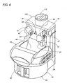
- the system includes a cleaning device which has a housing 20 with a base 30 and a stand 40 upstanding from a rear end of the base. Formed at the front end of the base 30 is a basin 50 which is configured to receive an operator head, i.e., a shaver head 12 of the shaver 10.
- the cleaning liquid is stored in a tank 100 detachably mounted to the stand 40 and is connected to the basin 50 for supplying the liquid into the basin and for recovering the liquid therefrom.
- the device includes a pump 70 which is controlled to circulate the cleaning liquid between the tank 100 and the basin 50 for cleaning the shaver head 12. The cleaning operation continues for a predetermined period. Thereafter, a control is made to collect the liquid from the basin 50 into the tank 100, details of which will be discussed later. Upon recovery of the liquid into the tank, a fan 200 is actuated to produce a forced air flow over the head 12 for drying the same.
- a drip pan 60 is disposed immediately below the basin 50 for collecting the liquid dripping and/or overflowing from the basin 50.
- the drip pan 60 has a top opening which communicates with a drain port 52 at the bottom center of the basin 50, and also with an overflow duct 34 leading to an upper edge of the basin 50.
- the drip pan 60 has a filter 63 for entrapping contaminants dislodged from the shaver head 12 and carried on the liquid dribbling through the drain port 52 into the drip pan 60.
- the liquid thus cleared of the contaminants is fed through a connection port 65 to a fluid intake channel 22 leading to the tank 100.
- the pump 70 is disposed in the fluid intake channel 22 for drawing the liquid from the basin 50.
- the fluid intake channel 22 is open to the atmosphere through the drain port 52, the overflow duct 34, and also through an air vent 36 formed in the base 30 around the basin 50.
- the tank 100 is provided in the form of a hermetically sealed container having an inlet and an outlet.
- the inlet is defined by a fluid inlet tube 102 which is detachably connected to the fluid intake channel 22 for taking in the liquid and/or the air.
- the outlet is defined by a liquid outlet tube 104 which is detachably connected to a liquid supply channel 24 formed in the housing 20 and leading to a spout 25 upwardly of the basin 50, as best shown in FIG. 9 , for flowing the liquid down into the basin 50.
- the liquid outlet tube 104 is connected to a U-shaped sucking tube 105 which extends deep into the tank 100 to a point adjacent to the bottom of the tank for sucking the liquid.
- the tank 100 is formed with an air exhaust tube 106 detachably connected to an air exhaust channel 26 which extends within the housing 20 and is open to the atmosphere through ventilation windows 28 or clearances in the walls of the housing 20.
- An air valve 80 is disposed in the air exhaust channel 26 to selectively close the tank and open it to the atmosphere.
- the air valve 80 is realized by a normally-closed electromagnetic valve which opens upon being energized or supplied with an electric current.
- a cap 112 is detachably and sealingly mounted in a filling port 110 in the upper end of the tank 100 for replacing or replenishing the liquid.
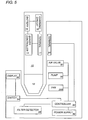
- the device includes a power supply 90 providing an electric power to various electrical parts, and a controller 92 responsible for controlled operations of the associated parts.
- a switch 94 When a switch 94 is activated, the controller 92 responds to provide a supply mode and a recovery mode in sequence.
- the pump 70 In the supply mode, the pump 70 is activated with the air valve 80 being kept closed, i.e., the tank being kept hermetically sealed. Initially, the basin 50 is substantially free from the liquid such that only the air is drawn and accumulated in the tank 100 to increase the inside air pressure. As the air pressure increases, the liquid in the tank 100 is forced to expel out through the liquid outlet tube 104 and the liquid supply channel 24 into the basin 50.
- the drain port 52 of the basin 50 is dimensioned such that the flow rate of the liquid dripping into the drip pan 60 is smaller than that of the liquid being supplied from the tank 100, thereby increasing the amount of the liquid in the basin 50.
- an extra amount of the liquid is caused to overflow into the drip pan 60, maintaining the liquid in the basin 50 at a constant level.
- the air is continuously drawn into the tank with the superfluous liquid to keep supplying the liquid into the basin 50, i.e., circulating the liquid between the tank 100 and the basin 50 for cleaning the shaver head 12.
- the supply mode continues over a predetermined time period during which the shaver head is activated intermittently or continuously to shake the contaminants off, enhancing the cleaning effect.
- the supply mode is automatically followed by the recovery mode in which the pump 70 is activated with the air valve 80 kept opened to collect the liquid from the basin 50 through the drip pan 60 into the tank 100.
- the air valve 80 With the air valve 80 being opened, i.e., the tank 100 opened to the atmosphere, the air drawn by the pump 70 is exhausted through the air valve 80 so as to recover the liquid and collect only the liquid in the tank 100.
- the recovery mode continues over a predetermined time period to collect the whole liquid into the tank. Near the end of the period, the shaver head is controlled to be activated for shaking the liquid off. Thereafter, the fan 200 is activated to dry the shaver head with or without the shaver head being actuated.
- the supply mode and the recovery mode are accomplished with the use of a single pump and the air valve.
- the tank 100 is L-shaped to have a wide header section 114 and a vertically elongated section 116 overlapping the rear face of the stand 40.
- the tank 100 is mounted on the housing 20 with the horizontal section 114 resting on a mounting face 41 on top of the stand 40.
- the fluid inlet tube 102, the liquid outlet tube 104, and the air exhaust tube 106 are integrally formed with the tank 100 to project on the bottom of the header section 114 for detachably connection with the fluid intake channel 22, the liquid supply channel 24, and the air exhaust channel 26, respectively.
- the ends of the channels 22, 24, and 26 are integrated into a combination socket 28 formed in the mounting face 41, as shown in FIG. 10 .
- the tank 100 can be attached to the housing 20 from the above.
- the device further includes a filter detector 98 which issues a stop signal when the drip pan 60 is not in position below the basin 50. In response to the stop signal, the controller 92 deactivates the pump 70 and the associated parts to cease the above operation.
- a display 96 is included in the device to give information about which one of the supply mode and the recovery mode is proceeding, and the elapsed time.
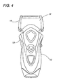
- a signal transmitting terminal 91 is provided on the side of the housing 20 for transmitting an electric signal that is received in a shaver controller 14 to activate the shaver head 12 or a charging circuit 16 for charging a battery 15. As best shown in FIGS.
- the terminal 91 includes a set of contacts 93 exposed on the front wall of the stand 40 for contact with a corresponding set of pads 13 formed on the exterior of the shaver 10.
- the pads define a signal receiving terminal 11 represented in FIG. 5 through which the signal is transmitted to the shaver controller 14.
- the contacts 93 i.e., the terminal 91 is located intermediate the height of the stand 40 for intimate contact with the pads 13 or the receiving terminal 11 when the shaver 10 is held upside down to place the shaver head 12 into the basin 50.
- the housing 20 may include the signal transmitting terminal in the form of a primary winding 93A for transformer coupling with a secondary winding 13A placed within the shaver as the signal receiving terminal.
- both of the windings can be concealed within the housing and shaver, respectively.
- the stand 40 carries a holding means, i.e., a mechanism of holding the shaver 10 in position.
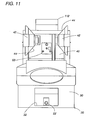
- the mechanism includes a pair of clasps 42 which are spaced widthwise with respect to the height dimension of the housing 20 and are pivotally supported to the stand 40 to be movable between a holding position of bracing the shaver 10 and a releasing position permitting the removable of the shaver.
- the clasps 42 are biased by coil springs 43 to the holding position in which the clasps 42 engage the opposite sides of the shaver 10.
- Each of the clasps 42 is formed at its upper and lower end respectively with inclined guides 44 for sliding contact with tapered head sides 18 as well as top tapered sides 19 adjacent to the shaver head 12, as shown in FIG.
- the clasps 42 can be forced to open temporarily in the release position when the shaver is moved vertically to place the shaver head 12 into the basin 50, allowing the easy attachment of the shaver, after which the clasps close by the action of the springs into the holding position. Also, when the shaver is moved vertically to pull the shaver head 12 out of the basin 50, the clasps 42 are forced to open by contact with the top tapered sides 19 of the shaver, permitting the easy detachment of the shaver from the device. In the holding position, the clasps 42 urges the shaver 10 towards the stand 40 in order to keep the pads 13 of the receiving terminal 11 pressed against the corresponding contacts 93 for reliable signal transmission therebetween.
- the clasps 42 establishes a pulling unit that pulls the apparatus 10 towards the stand 40, i.e., a portion of the housing 20 opposed to the apparatus under the bias of the springs 43 for reliable electrical interconnection between the apparatus 10 and the device.
- the stand 40 has a front face which is configured to guide the apparatus 10 to a holding position where the shaver head 12 is received within the basin 50.
- the front face has is a guide face 46 which is inclined with respect to a vertical or height axis of the housing 20 and which is formed at its lower end with a stopper 48 for abutting against a shoulder of the apparatus or shaver 10 .
- the stopper 48 is positioned so that the apparatus 10 is caused to lean upon the front face of the stand by its own weight, thereby urging the pads 13 of the receiving terminal 11 against the contacts 93 of the transmitting terminal 91 for reliable electrical contact therebetween. In this sense, the electrical connection can be made successfully even without relying upon the springs 43 of the clasps 42.
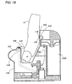
- FIG. 16 shows a modification of the above system in which the housing 20 carries a holding means 40B in the form of a pushing unit that includes a pusher 42B movably supported by the housing 20.
- the pusher 42B is normally biased by a spring 43B to have its end abutted against the shaver 10, thereby holding the shaver in position and at the same time developing a contact pressure between the signal transmitting terminal 91B of the housing 20 and the signal receiving terminal 11B of the shaver for reliable electrical interconnection therebetween.
- like parts are designated by like reference numerals with a suffix letter of "B".
- the drip pan 60 is made detachable to the housing 20 for easy cleaning of the filter 63 as well as the pan 60 itself.
- the drip pan 60 is provided in the form of a drawer having a front handle 64 and the top opening which comes into fluid communication with the drain port 52 of the basin 50, the air vent 36, and the overflow duct 34 for receiving the liquid and/or the air therethrough.
- a recess 32 is formed at the front end of the base 30 immediately below the basin 50 to accommodate the drip pan 60.
- the inner bottom of the pan 60 is inclined downwardly towards the connection port 65 for smoothly guiding the liquid to the fluid intake channel 22. As shown in FIG.
- the interior space of the drip pan 60 is divided by the filter 63 into a first chamber 61 and a second chamber 62.
- the first chamber 61 is in direct open communication with the drain port 52 and the overflow duct 34 for collecting the liquid and/or the air respectively therethrough, thereby depositing the contaminants carried by the liquid on the filter 63.
- the second chamber 62 is in direct open communication with the air vent 36 and with the connection port 65 for feeding the liquid cleared of the contaminants as well as the outside air into the fluid intake channel 22.
- the filter 63 is bent into an L-shaped section, as shown in FIG. 14 .
- the pan 60 is formed with an electrode (not shown) which is sensed by the filter detector to determined the presence of the pan in the recess 32.
- the drip pan 60 is designed to have a liquid storing capacity larger than that of the basin 50 in order to collect the entire volume of the liquid from the basin 50 even if the pump 70 should stop during the supply mode.
- the filter is preferred to have a filtering area of 700 mm 2 or more. Further, instead of providing the removable drip pan 60, the filter 63 alone may be detachable to the housing for frequent cleaning purpose.
- the cleaning system in accordance with the present invention can be equally applied for cleaning the epilating head of a hand-held epilator or other operator head of similar hair removing apparatus.
Landscapes
- Life Sciences & Earth Sciences (AREA)
- Forests & Forestry (AREA)
- Engineering & Computer Science (AREA)
- Mechanical Engineering (AREA)
- Dry Shavers And Clippers (AREA)
- Bidet-Like Cleaning Device And Other Flush Toilet Accessories (AREA)
Claims (9)
- Reinigungssystem mit einer Haarentfernungsvorrichtung (10) und einem Reinigungsgerät, wobei die Vorrichtung eine Höhe aufweist und an ihrem oberen Ende einen Arbeitskopf (12) hat und wobei die Vorrichtung eine extern steuerbare elektrische Schaltung (14) zum Ansteuern des Arbeitskopfes entsprechend einem externen elektrischen Signal enthält und wobei das Reinigungsgerät Folgendes aufweist:- ein Gehäuse (20), das so konfiguriert ist, dass es die Vorrichtung auf dem Kopf stehend hält;- ein Becken (50), das in dem Gehäuse zum Aufnehmen des Arbeitskopfes ausgebildet ist;- einen Behälter (100), der an dem Gehäuse vorgesehen ist, um eine Menge einer Reinigungsflüssigkeit aufzunehmen;- ein Zuführmittel (70) zum Zuführen der Reinigungsflüssigkeit aus dem Behälter zu dem Becken zum Reinigen des Arbeitskopfes und- ein Steuergerät (92) zum Aktivieren der Zuführmittel und zum Bereitstellen des elektrischen Signals,wobei
das Gehäuse mit Signalübertragungsmitteln (91, 93; 93A) zum Übertragen des elektrischen Signals ausgebildet ist,
die Haarentfernungsvorrichtung (10) Signalempfangsmittel (11, 13; 13A) hat, die mit den Signalsübertragungsmitteln elektrisch in Kontakt kommen, um das elektrische Signal an die elektrische Schaltung zu übertragen, wenn die Vorrichtung von dem Gehäuse gehalten wird,
wobei die Signalübertragungsmittel an einem Teil des Gehäuses oberhalb des Beckens angeordnet sind,
dadurch gekennzeichnet, dass
die elektrische Schaltung (14) so konfiguriert ist, dass sie den Arbeitskopf (12) ansteuert und die Haarentfernungsvorrichtung (10) entsprechend dem elektrischen Signal auflädt, und
die Signalempfangsmittel innerhalb der Höhe der Vorrichtung (10) angeordnet sind und
sich ein Mechanismus oder Teile für die elektrischen Verbindungen zwischen den Signalübertragungsmitteln und den Signalempfangsmitteln innerhalb der Höhe der Vorrichtung, die von dem Gehäuse des Geräts gehalten wird, befinden. - Reinigungssystem nach Anspruch 1, dadurch gekennzeichnet, dass
die Signalempfangsmittel Kontaktstellen (13) aufweisen, die an der Außenseite des Gehäuses der Vorrichtung ausgebildet sind, und
die Signalübertragungsmittel eine Gruppe von Kontakten (93), die an der Außenseite des Gehäuses freiliegen, für einen Druckkontakt mit den entsprechenden Kontaktstellen aufweisen. - Reinigungssystem nach Anspruch 1, dadurch gekennzeichnet, dass die Signalübertragungsmittel eine Primärwicklung (93A) aufweisen, die in dem Gehäuse verdeckt angeordnet ist und die mit einer Sekundärwicklung (13A), die in der Vorrichtung gehalten ist, elektromagnetisch gekoppelt ist,
wobei
die Primärwicklung mit dem Steuergerät elektrisch gekoppelt ist und
die Sekundärwicklung mit der elektrischen Schaltung der Vorrichtung elektrisch gekoppelt ist und die Signalempfangsmittel definiert. - Reinigungssystem nach Anspruch 1, dadurch gekennzeichnet, dass das Gehäuse mit Haltemitteln (42) versehen ist, die die Vorrichtung in einer Position halten, in der die Signalübertragungsmittel in elektrischer Verbindung mit den Signalempfangsmitteln gehalten werden.
- Reinigungssystem nach Anspruch 4, dadurch gekennzeichnet, dass die Haltemittel einen Mechanismus haben, der eine Vorspannung zum Drücken der Signalübertragungsmittel auf die Signalempfangsmittel hin erzeugt.
- Reinigungssystem nach Anspruch 5, dadurch gekennzeichnet, dass das Gehäuse mit einer Zug-Einheit (42) versehen ist, die die Vorrichtung so zu dem Gehäuse zieht, dass der Mechanismus definiert wird.
- Reinigungssystem nach Anspruch 5, dadurch gekennzeichnet, dass das Gehäuse mit einer Druck-Einheit (42B) versehen ist, die die Vorrichtung so gegen das Gehäuse drückt, dass der Mechanismus definiert wird.
- Reinigungssystem nach Anspruch 5, dadurch gekennzeichnet, dass das Gehäuse eine Anlagefläche (46) zum Stützen der Vorrichtung hat, wobei die Anlagefläche in Bezug auf eine Höhenachse des Gehäuses geneigt ist und mit einem Anschlag (48) versehen ist, um mit einem Teil der Vorrichtung in Eingriff zu kommen, so dass die Vorrichtung entlang der geneigten Anlagefläche geführt wird und die Vorspannkraft durch ihr eigenes Gewicht erzeugt, wenn sie mit dem Anschlag in Eingriff kommt.
- Reinigungssystem nach Anspruch 1, dadurch gekennzeichnet, dass die Signalübertragungsmittel einen Signalübertragungs-Anschluss (91) aufweisen, der innerhalb der Höhe eines Standes (40) angeordnet ist, der von einem hinteren Ende eines Unterteils (30) des Gehäuses (20) aufrecht steht.
Priority Applications (1)
| Application Number | Priority Date | Filing Date | Title |
|---|---|---|---|
| EP10184352.2A EP2308338B1 (de) | 2003-01-21 | 2004-01-19 | Reinigungssystem für einen Haarentfernungsapparat |
Applications Claiming Priority (3)
| Application Number | Priority Date | Filing Date | Title |
|---|---|---|---|
| JP2003012812A JP4036102B2 (ja) | 2003-01-21 | 2003-01-21 | 除毛器具の洗浄システム |
| JP2003012812 | 2003-01-21 | ||
| PCT/JP2004/000382 WO2004066780A1 (en) | 2003-01-21 | 2004-01-19 | Cleaning system of a hair removing apparatus |
Related Child Applications (2)
| Application Number | Title | Priority Date | Filing Date |
|---|---|---|---|
| EP10184352.2A Division EP2308338B1 (de) | 2003-01-21 | 2004-01-19 | Reinigungssystem für einen Haarentfernungsapparat |
| EP10184352.2 Division-Into | 2010-09-30 |
Publications (2)
| Publication Number | Publication Date |
|---|---|
| EP1523254A1 EP1523254A1 (de) | 2005-04-20 |
| EP1523254B1 true EP1523254B1 (de) | 2011-02-23 |
Family
ID=32820532
Family Applications (2)
| Application Number | Title | Priority Date | Filing Date |
|---|---|---|---|
| EP04703241A Expired - Lifetime EP1523254B1 (de) | 2003-01-21 | 2004-01-19 | Reinigungssystem für ein haarentfernungsapparat |
| EP10184352.2A Expired - Lifetime EP2308338B1 (de) | 2003-01-21 | 2004-01-19 | Reinigungssystem für einen Haarentfernungsapparat |
Family Applications After (1)
| Application Number | Title | Priority Date | Filing Date |
|---|---|---|---|
| EP10184352.2A Expired - Lifetime EP2308338B1 (de) | 2003-01-21 | 2004-01-19 | Reinigungssystem für einen Haarentfernungsapparat |
Country Status (8)
| Country | Link |
|---|---|
| US (2) | US7588039B2 (de) |
| EP (2) | EP1523254B1 (de) |
| JP (1) | JP4036102B2 (de) |
| KR (1) | KR100667963B1 (de) |
| CN (1) | CN100415139C (de) |
| AT (1) | ATE499018T1 (de) |
| DE (1) | DE602004031491D1 (de) |
| WO (1) | WO2004066780A1 (de) |
Cited By (1)
| Publication number | Priority date | Publication date | Assignee | Title |
|---|---|---|---|---|
| EP4403080A4 (de) * | 2022-11-17 | 2025-03-26 | Jiangsu Midea Cleaning Appliances Co., Ltd. | Haarschneideanordnung, reinigungsvorrichtung und schneidesteuerungsverfahren |
Families Citing this family (30)
| Publication number | Priority date | Publication date | Assignee | Title |
|---|---|---|---|---|
| US7150285B2 (en) * | 2003-01-21 | 2006-12-19 | Matsushita Electric Works, Ltd. | Cleaning device for a hair removing apparatus |
| JP4036102B2 (ja) * | 2003-01-21 | 2008-01-23 | 松下電工株式会社 | 除毛器具の洗浄システム |
| DE10316935A1 (de) * | 2003-04-12 | 2004-11-04 | Braun Gmbh | System aus einem elektrischen Kleingerät und einem diesem zugeordneten elektrischen Zusatzgerät |
| JP4650135B2 (ja) * | 2005-07-15 | 2011-03-16 | パナソニック電工株式会社 | 電気機器システム |
| JP4544092B2 (ja) * | 2005-08-12 | 2010-09-15 | パナソニック電工株式会社 | 電気カミソリシステム |
| JP4375316B2 (ja) * | 2005-09-27 | 2009-12-02 | パナソニック電工株式会社 | 剤供給装置 |
| JP4438774B2 (ja) * | 2006-07-14 | 2010-03-24 | パナソニック電工株式会社 | シェーバ洗浄装置およびシェーバシステム |
| JP4165582B2 (ja) | 2006-07-14 | 2008-10-15 | 松下電工株式会社 | 電気かみそりと充電器との保持構造 |
| JP4697079B2 (ja) * | 2006-07-20 | 2011-06-08 | パナソニック電工株式会社 | シェーバ |
| JP2008023120A (ja) | 2006-07-21 | 2008-02-07 | Matsushita Electric Works Ltd | 除毛器具の洗浄装置 |
| JP4329840B2 (ja) | 2007-05-14 | 2009-09-09 | パナソニック電工株式会社 | 体毛処理器具用乾燥器 |
| JP4400646B2 (ja) | 2007-05-14 | 2010-01-20 | パナソニック電工株式会社 | 体毛処理器具用乾燥器 |
| USD613684S1 (en) | 2008-12-19 | 2010-04-13 | Panasonic Electric Works Co., Ltd. | Charger with washing apparatus |
| US8939161B2 (en) * | 2009-03-24 | 2015-01-27 | Spectrum Brands, Inc. | Cleaning system for an electric shaver |
| US8177918B2 (en) | 2009-03-24 | 2012-05-15 | Rovcal, LLC | Cleaning system for an electric shaver |
| EP2543274B1 (de) * | 2011-07-06 | 2017-08-23 | Braun GmbH | Elektrisch betriebene Reinigungsvorrichtung für Rasierapparat |
| JP2013022475A (ja) * | 2011-07-15 | 2013-02-04 | Panasonic Corp | 洗浄装置 |
| JP5873987B2 (ja) | 2011-10-21 | 2016-03-01 | パナソニックIpマネジメント株式会社 | 電気かみそりと充電器との保持構造 |
| JP6008274B2 (ja) * | 2012-04-27 | 2016-10-19 | パナソニックIpマネジメント株式会社 | 小型電気機器の接続装置 |
| US20140208601A1 (en) * | 2012-09-27 | 2014-07-31 | ShaveSimpl, Inc. | Wet shaving apparatus rinsing device |
| RU2649949C2 (ru) * | 2013-09-30 | 2018-04-05 | Конинклейке Филипс Н.В. | Система очистки бреющего узла |
| JP2019072097A (ja) * | 2017-10-13 | 2019-05-16 | 株式会社泉精器製作所 | 電気かみそり用洗浄器及び電気かみそり洗浄システム |
| CN107802355B (zh) * | 2017-11-22 | 2020-03-03 | 青岛市黄岛区中心医院 | 一种护理科用备皮护理装置的调教方法 |
| EP3569094B1 (de) | 2018-05-15 | 2023-05-03 | Braun GmbH | Reinigungs- und ladestation |
| EP3569096B1 (de) | 2018-05-15 | 2023-06-28 | Braun GmbH | Reinigungs- und ladestation |
| EP3569095A1 (de) | 2018-05-15 | 2019-11-20 | Braun GmbH | Reinigungs- und ladestation |
| EP3771529A1 (de) * | 2019-08-02 | 2021-02-03 | Koninklijke Philips N.V. | Reinigungsvorrichtung zur reinigung einer rasiervorrichtung und rasiersystem mit solch einer reinigungsvorrichtung |
| USD1010324S1 (en) * | 2019-09-03 | 2024-01-09 | Koninklijke Philips N.V. | Cleansing brush for shaver |
| JP6806950B1 (ja) * | 2020-09-10 | 2021-01-06 | マクセルイズミ株式会社 | 洗浄器 |
| DE102024123651A1 (de) * | 2024-08-19 | 2026-02-19 | Anthony Yankah Stölting | Reinigungsvorrichtung für Haarschneidemaschinen sowie Verfahren zum Reinigen einer Haarschneidemaschine |
Family Cites Families (16)
| Publication number | Priority date | Publication date | Assignee | Title |
|---|---|---|---|---|
| US3659180A (en) * | 1969-01-21 | 1972-04-25 | Andis Clipper Co | Self-charging appliance and stand |
| US4092580A (en) * | 1975-03-12 | 1978-05-30 | Prinsze Onno M | Energizer apparatus for rechargeable flashlight batteries |
| JPS57145684A (en) * | 1981-02-28 | 1982-09-08 | Matsushita Electric Works Ltd | Charger for electric razor |
| JPH04221593A (ja) * | 1990-12-25 | 1992-08-12 | Matsushita Electric Works Ltd | 充電器 |
| JPH05234763A (ja) * | 1991-06-28 | 1993-09-10 | Matsushita Electric Works Ltd | 充電式電気機器 |
| DE4402238C2 (de) * | 1994-01-26 | 1996-09-26 | Braun Ag | Reinigungsvorrichtung für den Scherkopf eines Trockenrasierers |
| US5828966A (en) | 1996-05-23 | 1998-10-27 | Davis; Russell | Universal charging cradle for cordless telephones |
| DE19705975C2 (de) | 1997-02-17 | 2000-03-30 | Braun Gmbh | Reinigungsvorrichtung für einen Trockenrasierapparat |
| DE19705977C1 (de) | 1997-02-17 | 1998-03-05 | Braun Ag | Reinigungsvorrichtung für einen Trockenrasierapparat |
| DE19817273A1 (de) * | 1998-04-18 | 1999-10-21 | Braun Gmbh | Verfahren zur Datenübertragung zwischen einem Elektrokleingerät und einem mit diesem verbindbaren elektrischen Zusatzgerät, sowie entsprechend ausgestattete Geräte |
| CN2342947Y (zh) | 1998-10-21 | 1999-10-13 | 浙江超人集团有限公司 | 电动剃须刀 |
| DE19921677A1 (de) * | 1999-05-18 | 2000-11-23 | Braun Gmbh | Zusatzgerät für ein Elektrokleingerät und Verfahren zur Erkennung einer elektrischen und/oder magnetischen Verbindung zwischen den Geräten |
| US6313604B1 (en) * | 2000-08-01 | 2001-11-06 | Han-Liang Chen | Charging seat for a rechargeable flashlight |
| DE10222716A1 (de) * | 2002-05-23 | 2003-12-11 | Braun Gmbh | Reinigungsvorrichtung für den Scherkopf eines Trockenrasierapparates |
| JP4036102B2 (ja) * | 2003-01-21 | 2008-01-23 | 松下電工株式会社 | 除毛器具の洗浄システム |
| US7150285B2 (en) * | 2003-01-21 | 2006-12-19 | Matsushita Electric Works, Ltd. | Cleaning device for a hair removing apparatus |
-
2003
- 2003-01-21 JP JP2003012812A patent/JP4036102B2/ja not_active Expired - Lifetime
-
2004
- 2004-01-19 CN CNB2004800007823A patent/CN100415139C/zh not_active Expired - Lifetime
- 2004-01-19 US US10/525,205 patent/US7588039B2/en not_active Expired - Lifetime
- 2004-01-19 EP EP04703241A patent/EP1523254B1/de not_active Expired - Lifetime
- 2004-01-19 WO PCT/JP2004/000382 patent/WO2004066780A1/en not_active Ceased
- 2004-01-19 AT AT04703241T patent/ATE499018T1/de not_active IP Right Cessation
- 2004-01-19 DE DE602004031491T patent/DE602004031491D1/de not_active Expired - Lifetime
- 2004-01-19 KR KR1020057002840A patent/KR100667963B1/ko not_active Expired - Lifetime
- 2004-01-19 EP EP10184352.2A patent/EP2308338B1/de not_active Expired - Lifetime
-
2009
- 2009-08-31 US US12/551,560 patent/US7984722B2/en not_active Expired - Lifetime
Cited By (1)
| Publication number | Priority date | Publication date | Assignee | Title |
|---|---|---|---|---|
| EP4403080A4 (de) * | 2022-11-17 | 2025-03-26 | Jiangsu Midea Cleaning Appliances Co., Ltd. | Haarschneideanordnung, reinigungsvorrichtung und schneidesteuerungsverfahren |
Also Published As
| Publication number | Publication date |
|---|---|
| DE602004031491D1 (de) | 2011-04-07 |
| ATE499018T1 (de) | 2011-03-15 |
| EP2308338A2 (de) | 2011-04-13 |
| CN1700871A (zh) | 2005-11-23 |
| US7984722B2 (en) | 2011-07-26 |
| EP1523254A1 (de) | 2005-04-20 |
| KR20050034737A (ko) | 2005-04-14 |
| US20090314317A1 (en) | 2009-12-24 |
| US20060011225A1 (en) | 2006-01-19 |
| EP2308338A3 (de) | 2013-11-20 |
| US7588039B2 (en) | 2009-09-15 |
| JP4036102B2 (ja) | 2008-01-23 |
| WO2004066780A1 (en) | 2004-08-12 |
| JP2004261208A (ja) | 2004-09-24 |
| KR100667963B1 (ko) | 2007-01-11 |
| CN100415139C (zh) | 2008-09-03 |
| EP2308338B1 (de) | 2014-12-03 |
Similar Documents
| Publication | Publication Date | Title |
|---|---|---|
| US7984722B2 (en) | Cleaning system of a hair removing apparatus | |
| EP1440628B1 (de) | Reinigungsvorrichtung für ein Haarentfernungsgerät | |
| EP1523255B1 (de) | Reinigungsvorrichtung für ein enthaarungsgerät | |
| EP1568295B1 (de) | Reinigungsvorrichtung für ein Haarentfernungsgerät und Reinigungsverfahren für dasselbe | |
| JP3652393B2 (ja) | 乾式ひげそり装置のひげそりヘッドのクリーニング装置 | |
| EP1609384B1 (de) | Reinigungsvorrichtung für ein elektrisches Haarentfernungsgerät | |
| EP1944137A1 (de) | Mittelzuführungsvorrichtung | |
| JP4075865B2 (ja) | 除毛器具の洗浄装置 | |
| JP2010162168A (ja) | 洗浄装置 |
Legal Events
| Date | Code | Title | Description |
|---|---|---|---|
| PUAI | Public reference made under article 153(3) epc to a published international application that has entered the european phase |
Free format text: ORIGINAL CODE: 0009012 |
|
| 17P | Request for examination filed |
Effective date: 20050218 |
|
| AK | Designated contracting states |
Kind code of ref document: A1 Designated state(s): AT BE BG CH CY CZ DE DK EE ES FI FR GB GR HU IE IT LI LU MC NL PT RO SE SI SK TR |
|
| AX | Request for extension of the european patent |
Extension state: AL LT LV MK |
|
| DAX | Request for extension of the european patent (deleted) | ||
| 17Q | First examination report despatched |
Effective date: 20080214 |
|
| RAP1 | Party data changed (applicant data changed or rights of an application transferred) |
Owner name: PANASONIC ELECTRIC WORKS CO., LTD. |
|
| GRAP | Despatch of communication of intention to grant a patent |
Free format text: ORIGINAL CODE: EPIDOSNIGR1 |
|
| GRAS | Grant fee paid |
Free format text: ORIGINAL CODE: EPIDOSNIGR3 |
|
| GRAA | (expected) grant |
Free format text: ORIGINAL CODE: 0009210 |
|
| RIN1 | Information on inventor provided before grant (corrected) |
Inventor name: SHIGETA, HIROSHI Inventor name: IBUKI, YASUO Inventor name: TANIGUCHI, FUMIO Inventor name: IWASAKI, JYUZAEMON Inventor name: SAITO, ATSUHIRO Inventor name: KAMEOKA, HIROYUKI Inventor name: YAMASHITA, MIKIHIRO Inventor name: YANAGI, KOTARO |
|
| AK | Designated contracting states |
Kind code of ref document: B1 Designated state(s): AT BE BG CH CY CZ DE DK EE ES FI FR GB GR HU IE IT LI LU MC NL PT RO SE SI SK TR |
|
| REG | Reference to a national code |
Ref country code: GB Ref legal event code: FG4D |
|
| REG | Reference to a national code |
Ref country code: CH Ref legal event code: EP |
|
| REG | Reference to a national code |
Ref country code: IE Ref legal event code: FG4D |
|
| REF | Corresponds to: |
Ref document number: 602004031491 Country of ref document: DE Date of ref document: 20110407 Kind code of ref document: P |
|
| REG | Reference to a national code |
Ref country code: DE Ref legal event code: R096 Ref document number: 602004031491 Country of ref document: DE Effective date: 20110407 |
|
| REG | Reference to a national code |
Ref country code: NL Ref legal event code: T3 |
|
| PG25 | Lapsed in a contracting state [announced via postgrant information from national office to epo] |
Ref country code: GR Free format text: LAPSE BECAUSE OF FAILURE TO SUBMIT A TRANSLATION OF THE DESCRIPTION OR TO PAY THE FEE WITHIN THE PRESCRIBED TIME-LIMIT Effective date: 20110524 Ref country code: SE Free format text: LAPSE BECAUSE OF FAILURE TO SUBMIT A TRANSLATION OF THE DESCRIPTION OR TO PAY THE FEE WITHIN THE PRESCRIBED TIME-LIMIT Effective date: 20110223 Ref country code: PT Free format text: LAPSE BECAUSE OF FAILURE TO SUBMIT A TRANSLATION OF THE DESCRIPTION OR TO PAY THE FEE WITHIN THE PRESCRIBED TIME-LIMIT Effective date: 20110623 Ref country code: ES Free format text: LAPSE BECAUSE OF FAILURE TO SUBMIT A TRANSLATION OF THE DESCRIPTION OR TO PAY THE FEE WITHIN THE PRESCRIBED TIME-LIMIT Effective date: 20110603 |
|
| PG25 | Lapsed in a contracting state [announced via postgrant information from national office to epo] |
Ref country code: FI Free format text: LAPSE BECAUSE OF FAILURE TO SUBMIT A TRANSLATION OF THE DESCRIPTION OR TO PAY THE FEE WITHIN THE PRESCRIBED TIME-LIMIT Effective date: 20110223 Ref country code: CY Free format text: LAPSE BECAUSE OF FAILURE TO SUBMIT A TRANSLATION OF THE DESCRIPTION OR TO PAY THE FEE WITHIN THE PRESCRIBED TIME-LIMIT Effective date: 20110223 Ref country code: SI Free format text: LAPSE BECAUSE OF FAILURE TO SUBMIT A TRANSLATION OF THE DESCRIPTION OR TO PAY THE FEE WITHIN THE PRESCRIBED TIME-LIMIT Effective date: 20110223 Ref country code: BG Free format text: LAPSE BECAUSE OF FAILURE TO SUBMIT A TRANSLATION OF THE DESCRIPTION OR TO PAY THE FEE WITHIN THE PRESCRIBED TIME-LIMIT Effective date: 20110523 Ref country code: AT Free format text: LAPSE BECAUSE OF FAILURE TO SUBMIT A TRANSLATION OF THE DESCRIPTION OR TO PAY THE FEE WITHIN THE PRESCRIBED TIME-LIMIT Effective date: 20110223 Ref country code: BE Free format text: LAPSE BECAUSE OF FAILURE TO SUBMIT A TRANSLATION OF THE DESCRIPTION OR TO PAY THE FEE WITHIN THE PRESCRIBED TIME-LIMIT Effective date: 20110223 |
|
| PG25 | Lapsed in a contracting state [announced via postgrant information from national office to epo] |
Ref country code: DK Free format text: LAPSE BECAUSE OF FAILURE TO SUBMIT A TRANSLATION OF THE DESCRIPTION OR TO PAY THE FEE WITHIN THE PRESCRIBED TIME-LIMIT Effective date: 20110223 Ref country code: EE Free format text: LAPSE BECAUSE OF FAILURE TO SUBMIT A TRANSLATION OF THE DESCRIPTION OR TO PAY THE FEE WITHIN THE PRESCRIBED TIME-LIMIT Effective date: 20110223 |
|
| PG25 | Lapsed in a contracting state [announced via postgrant information from national office to epo] |
Ref country code: RO Free format text: LAPSE BECAUSE OF FAILURE TO SUBMIT A TRANSLATION OF THE DESCRIPTION OR TO PAY THE FEE WITHIN THE PRESCRIBED TIME-LIMIT Effective date: 20110223 Ref country code: CZ Free format text: LAPSE BECAUSE OF FAILURE TO SUBMIT A TRANSLATION OF THE DESCRIPTION OR TO PAY THE FEE WITHIN THE PRESCRIBED TIME-LIMIT Effective date: 20110223 Ref country code: SK Free format text: LAPSE BECAUSE OF FAILURE TO SUBMIT A TRANSLATION OF THE DESCRIPTION OR TO PAY THE FEE WITHIN THE PRESCRIBED TIME-LIMIT Effective date: 20110223 |
|
| PLBE | No opposition filed within time limit |
Free format text: ORIGINAL CODE: 0009261 |
|
| STAA | Information on the status of an ep patent application or granted ep patent |
Free format text: STATUS: NO OPPOSITION FILED WITHIN TIME LIMIT |
|
| 26N | No opposition filed |
Effective date: 20111124 |
|
| REG | Reference to a national code |
Ref country code: DE Ref legal event code: R097 Ref document number: 602004031491 Country of ref document: DE Effective date: 20111124 |
|
| PG25 | Lapsed in a contracting state [announced via postgrant information from national office to epo] |
Ref country code: IT Free format text: LAPSE BECAUSE OF FAILURE TO SUBMIT A TRANSLATION OF THE DESCRIPTION OR TO PAY THE FEE WITHIN THE PRESCRIBED TIME-LIMIT Effective date: 20110223 |
|
| PG25 | Lapsed in a contracting state [announced via postgrant information from national office to epo] |
Ref country code: MC Free format text: LAPSE BECAUSE OF NON-PAYMENT OF DUE FEES Effective date: 20120131 |
|
| REG | Reference to a national code |
Ref country code: CH Ref legal event code: PL |
|
| GBPC | Gb: european patent ceased through non-payment of renewal fee |
Effective date: 20120119 |
|
| REG | Reference to a national code |
Ref country code: FR Ref legal event code: ST Effective date: 20120928 |
|
| REG | Reference to a national code |
Ref country code: IE Ref legal event code: MM4A |
|
| PG25 | Lapsed in a contracting state [announced via postgrant information from national office to epo] |
Ref country code: LI Free format text: LAPSE BECAUSE OF NON-PAYMENT OF DUE FEES Effective date: 20120131 Ref country code: GB Free format text: LAPSE BECAUSE OF NON-PAYMENT OF DUE FEES Effective date: 20120119 Ref country code: CH Free format text: LAPSE BECAUSE OF NON-PAYMENT OF DUE FEES Effective date: 20120131 |
|
| PG25 | Lapsed in a contracting state [announced via postgrant information from national office to epo] |
Ref country code: FR Free format text: LAPSE BECAUSE OF NON-PAYMENT OF DUE FEES Effective date: 20120131 |
|
| PG25 | Lapsed in a contracting state [announced via postgrant information from national office to epo] |
Ref country code: IE Free format text: LAPSE BECAUSE OF NON-PAYMENT OF DUE FEES Effective date: 20120119 |
|
| PG25 | Lapsed in a contracting state [announced via postgrant information from national office to epo] |
Ref country code: TR Free format text: LAPSE BECAUSE OF FAILURE TO SUBMIT A TRANSLATION OF THE DESCRIPTION OR TO PAY THE FEE WITHIN THE PRESCRIBED TIME-LIMIT Effective date: 20110223 |
|
| PG25 | Lapsed in a contracting state [announced via postgrant information from national office to epo] |
Ref country code: LU Free format text: LAPSE BECAUSE OF NON-PAYMENT OF DUE FEES Effective date: 20120119 |
|
| PG25 | Lapsed in a contracting state [announced via postgrant information from national office to epo] |
Ref country code: HU Free format text: LAPSE BECAUSE OF FAILURE TO SUBMIT A TRANSLATION OF THE DESCRIPTION OR TO PAY THE FEE WITHIN THE PRESCRIBED TIME-LIMIT Effective date: 20040119 |
|
| PGFP | Annual fee paid to national office [announced via postgrant information from national office to epo] |
Ref country code: NL Payment date: 20221220 Year of fee payment: 20 |
|
| PGFP | Annual fee paid to national office [announced via postgrant information from national office to epo] |
Ref country code: DE Payment date: 20220308 Year of fee payment: 20 |
|
| REG | Reference to a national code |
Ref country code: DE Ref legal event code: R071 Ref document number: 602004031491 Country of ref document: DE |
|
| REG | Reference to a national code |
Ref country code: NL Ref legal event code: MK Effective date: 20240118 |