EP1523072A1 - Connecteur, système de connection et méthode d'assemblage - Google Patents
Connecteur, système de connection et méthode d'assemblage Download PDFInfo
- Publication number
- EP1523072A1 EP1523072A1 EP04024108A EP04024108A EP1523072A1 EP 1523072 A1 EP1523072 A1 EP 1523072A1 EP 04024108 A EP04024108 A EP 04024108A EP 04024108 A EP04024108 A EP 04024108A EP 1523072 A1 EP1523072 A1 EP 1523072A1
- Authority
- EP
- European Patent Office
- Prior art keywords
- slider
- connector
- portions
- guiding
- connector housing
- Prior art date
- Legal status (The legal status is an assumption and is not a legal conclusion. Google has not performed a legal analysis and makes no representation as to the accuracy of the status listed.)
- Granted
Links
Images


Classifications
-
- H—ELECTRICITY
- H01—ELECTRIC ELEMENTS
- H01R—ELECTRICALLY-CONDUCTIVE CONNECTIONS; STRUCTURAL ASSOCIATIONS OF A PLURALITY OF MUTUALLY-INSULATED ELECTRICAL CONNECTING ELEMENTS; COUPLING DEVICES; CURRENT COLLECTORS
- H01R13/00—Details of coupling devices of the kinds covered by groups H01R12/70 or H01R24/00 - H01R33/00
- H01R13/62—Means for facilitating engagement or disengagement of coupling parts or for holding them in engagement
- H01R13/629—Additional means for facilitating engagement or disengagement of coupling parts, e.g. aligning or guiding means, levers, gas pressure electrical locking indicators, manufacturing tolerances
-
- H—ELECTRICITY
- H01—ELECTRIC ELEMENTS
- H01R—ELECTRICALLY-CONDUCTIVE CONNECTIONS; STRUCTURAL ASSOCIATIONS OF A PLURALITY OF MUTUALLY-INSULATED ELECTRICAL CONNECTING ELEMENTS; COUPLING DEVICES; CURRENT COLLECTORS
- H01R13/00—Details of coupling devices of the kinds covered by groups H01R12/70 or H01R24/00 - H01R33/00
- H01R13/62—Means for facilitating engagement or disengagement of coupling parts or for holding them in engagement
- H01R13/627—Snap or like fastening
- H01R13/6271—Latching means integral with the housing
- H01R13/6272—Latching means integral with the housing comprising a single latching arm
-
- H—ELECTRICITY
- H01—ELECTRIC ELEMENTS
- H01R—ELECTRICALLY-CONDUCTIVE CONNECTIONS; STRUCTURAL ASSOCIATIONS OF A PLURALITY OF MUTUALLY-INSULATED ELECTRICAL CONNECTING ELEMENTS; COUPLING DEVICES; CURRENT COLLECTORS
- H01R13/00—Details of coupling devices of the kinds covered by groups H01R12/70 or H01R24/00 - H01R33/00
- H01R13/62—Means for facilitating engagement or disengagement of coupling parts or for holding them in engagement
- H01R13/629—Additional means for facilitating engagement or disengagement of coupling parts, e.g. aligning or guiding means, levers, gas pressure electrical locking indicators, manufacturing tolerances
- H01R13/633—Additional means for facilitating engagement or disengagement of coupling parts, e.g. aligning or guiding means, levers, gas pressure electrical locking indicators, manufacturing tolerances for disengagement only
- H01R13/635—Additional means for facilitating engagement or disengagement of coupling parts, e.g. aligning or guiding means, levers, gas pressure electrical locking indicators, manufacturing tolerances for disengagement only by mechanical pressure, e.g. spring force
Definitions
- the present invention relates to a connector provided with a partial connection preventing function.
- the present invention further relates to a connector assembly and to a method of assembling a connector assembly.
- this connector is comprised of a female housing 2 fittable into a receptacle 1 a of a mating male housing 1, a slider 3 assembled to be slidable forward and backward while being held in sliding contact with the upper surface of the female housing 2, and a compression coil spring 4 mounted while being squeezed between the slider 3 and the female housing 2.
- the slider 3 is pushed backward by the male housing 1, and the compression coil spring 4 is resiliently compressed by the slider 3 moving backward to accumulate such a biasing force as to separate the two housings 1, 2.
- This female housing 2 is provided with a restricting portion 5 which can be held in sliding contact with the upper surface of the slider 3, whereby sliding movements of the slider 3 can be guided while preventing the slider 3 from being displaced upward, i.e. raised.
- the slider 3 is provided with locking projections 6 engageable with receiving portions 7 provided on the female housing 2, thereby being prevented from coming out forward from an assembled position thereof. Since slanted guiding surfaces (not shown) are formed on the rear surfaces of the locking projections 6, the locking projections 6 can easily move over the receiving portions 7 upon mounting the slider 3 into the female housing 2 from front, thereby providing a good assembling operability. In the assembled state, the locking projections 6 are caused to escape into escaping grooves 8 formed behind the receiving portions 7.
- the present invention was developed in view of the above problem and an object thereof is to improving an assembling operation.
- a displacement of a slider is sufficiently restriected while ensuring a satisfactory assembling operation for the slider, thus improving overall operability of the assembling operation.
- a connector comprising:
- the biasing means When the two connector housings are connected, the biasing means is pushed by the other connector housing to accumulate such a biasing force as to separate the two connector housings. Accordingly, if the connecting operation is interrupted halfway, the biasing force accumulated in the biasing means is released to forcibly separate the two connector housings. Thus, a situation where the two connector housings are left partly connected can be prevented.
- the slider supporting the one end of the biasing means is permitted to move, thereby releasing the biasing force of the biasing member.
- the locking projection includes the restricting portion bulging more outward than the guiding surface and is engaged with the peripheral edge of the escaping groove to restrict the displacement of the slider along the direction intersecting with the moving direction of the slider.
- an area of engagement of the locking projection with the escaping groove can be increased by as much as the restricting portion bulges out from the guiding surface.
- the displacement of the slider can be sufficiently restricted.
- a satisfactory assembling operation can be ensured by providing the guiding surface as before.
- the slider supports one end of the biasing member and is permitted to move as the two connector housings are properly connected, thereby at least partly releasing the biasing force of the biasing member.
- a connector comprising:
- the slider prevents interlocking means interlocking the two connector housings properly connected with each other from being disengaged.
- the slider is mounted on one side surface of the one connector housing, and the restricting portion is provided at a side of the locking projection opposite from the mounting surface of the one connector housing.
- the displacement of the slider can be securely restricted by providing the restricting portion at the side of the locking projection opposite from the mounting surface.
- the slider comprises one or more pushable portions which can be pushed by one or more respective pushing portions provided on the mating connector housing as the two connector housings are connected.
- the pushable portions are formed with a overhanging surface and the pushing portions have a substantially correspondingly inclined surface.
- the connector housing and/or the slider comprise at least one disengagement guiding portion for guiding a disengagement of the pushable portion and the pushing portion before or when the two connector housings are substantially properly connected.
- a connector assembly comprising a connector according to the invention or a preferred embodiment thereof and a mating connector connectable with each other.
- an assembling or mounting method for assembling or mounting a connector assembly comprising the following steps:
- the slider supports one end of the biasing member and is permitted to move as the two connector housings are properly connected, thereby at least partly releasing the biasing force of the biasing member.
- a slider 40 and a compression coil spring S are at least partly assembled into or to or onto a male connector housing (hereinafter, merely “male housing 20") connectable with a female connector housing 10 (hereinafter, merely “female housing 10").
- male housing 20 engageable with a female connector housing 10
- female housing 10 engageable with engaging sides of the two housings 10, 20
- engaging sides of the two housings 10, 20 are referred to as front sides, and reference is made to all the figures except FIGS. 4, 5, 10 and 11 concerning vertical direction.
- the female housing 10 is made e.g. of a synthetic resin and substantially in the form of a block as a whole, wherein one or more (e.g. three) cavities 12 into which female terminal fittings 11 are at least partly insertable from an inserting side, preferably from behind, are arranged substantially side by side along widthwise direction are provided in the female housing 10.
- Each female terminal fitting 11 is comprised of a (preferably substantially box-shaped) main portion 11 a electrically connectable with a male terminal fitting 25, and a wire connection portion preferably comprising a barrel 11 b to be connected (preferably crimped or bent or folded into connection) with an end of a wire W, the main portion 11 a and the barrel portion 11 b being coupled one after the other.
- a locking groove 12a having an open front end is formed in the lateral (ceiling) surface of each cavity 12, and a (preferably substantially cantilever-shaped) locking portion 11 c formed at the lateral (upper) wall of the main portion 11a preferably by cutting and bending is engageable with the rear surface of the locking groove 12a.
- a retainer mount hole 13 is so formed in an intermediate portion (preferably in substantially longitudinal middles) of side surfaces of the female housing 10 as to cross the respective cavities 12, and a retainer 14 for locking the female terminal fittings 11 is at least partly mountable thereinto.
- the retainer 14 is movable in a direction intersecting an insertion direction of the terminal fittings 11 into the female connector housing 10 or substantially along widthwise direction between a partial locking or first position (not shown) where the insertion and withdrawal of the female terminal fittings 11 are permitted and a full locking or second position where the retainer 14 is engaged with jaw portions 11 d at (preferably the rear ends of) the main portions 11 a.
- the retainer mount hole 13 is open in the upper surface of the female housing 10
- the female housing 10 is reinforced by providing one or more, preferably a pair of reinforcing portions 15 bridging the front and rear edges of the retainer mount hole 13 or being provided close thereto (see FIGS. 2 and 13(A)).
- One or more, preferably a pair of pushing portions 16 project at positions substantially facing or corresponding to the reinforcing portions 15 from front on the lateral (upper) surface of the female housing 10.
- the pushing portions 16 can push or engage or interact with pushable portions 46 of the slider 40 of the male housing 20, and the front end positions thereof preferably are slightly receded from the front end of the female housing 10. Between the pushing portions 16 and the reinforcing portions 15 is defined such a space as to escape the pushable portions 46.
- a front surface 16a of each pushing portion 16 which is a surface for pushing the pushable portion 46 preferably is an overhanging or undercut surface sloped up or outward toward the front, whereas a rear surface 16b thereof is a slanted surface sloped up or outward toward the front (refer e.g. to FIG. 13).
- a lock portion 17 engageable with a lock arm 31 of the male housing 20 projects at an intermediate position (preferably a substantially widthwise middle position) of the lateral (upper) surface of the female housing 10 preferably between the reinforcing portions 15 and the pushing portions 16.
- a front surface 17a of the lock portion 17 is a slanted surface sloped up or outward toward the back in order to guide a movement of the lock arm 31 onto the lock portion 17.
- a rear surface 17b of the lock portion 17 which serves as a locking surface engageable with the lock arm 31 preferably is a substantially straight vertical surface.
- a disengaging groove 18 for permitting the at least partial entrance of resilient contact pieces 27a of a shorting terminal 27 of the male housing 20 is so formed as to be open forward and/or downward. The resilient contact pieces 27a can be pushed up by the peripheral edge of the disengaging groove 18.
- the male housing 20 is made e.g. of a synthetic resin, and is provided with a terminal accommodating portion 21 for at least partly accommodating the male terminal fittings 25 and the shorting terminal 27, a receptacle 22 into which the female housing 10 is at least partly fittable and which is coupled or integral or unitary to the front side of the terminal accommodating portion 21, and a partial connection preventing unit assembling portion 23 which is provided above or outward of the terminal accommodating portion 21 and the receptacle 22 and into which the slider 40 and the compression coil spring S are at least partly assembled to prevent a partial connection as shown in FIGS. 3 to 8 and 13.
- One or more bracket portion portions 24 on which unillustrated brackets are at least partly mountable are provided on the left surfaces of the terminal accommodating portion 21, the receptacle 22 and the assembling portion 23.
- One or more (e.g. three) cavities 26 into which the male terminal fittings 25 are at least partly insertable from an inserting side, preferably from behind, as shown in FIG. 7 are provided substantially side by side along widthwise direction in the terminal accommodating portion 21.
- Each male terminal fitting 25 includes a tab 25a electrically connectable with the female terminal fitting 11, a (preferably substantially box-shaped) main portion 25b, and a wire connection portion preferably comprising a barrel portion 25c to be connected (preferably crimped or bent or folded into connection) with an end of a wire W in this order from front side.
- a shorting-terminal accommodating chamber 28 for at least partly accommodating the shorting terminal 27 is provided preferably below the middle and left cavities 26 of FIG. 3 in the terminal accommodating portion 21 and is open sideways.
- the shorting terminal 27 has two or more resilient contact pieces 27a which can at least partly project into the receptacle 22 and can be resiliently brought into contact with the contact surfaces (preferably lower surfaces) of the tabs 25a and, therefore, can short the corresponding two or more male terminal fittings 25.
- the respective cavities 26 are formed with locking grooves 26a engageable with respective locking portions 25d of the corresponding main portion 25b, and the terminal accommodating portion 21 is formed with a retainer mount hole 30 into which a retainer 29 for locking jaw portions 25e of the main portions 25b is at least partly mountable. No detailed description is given on them since they take constructions similar to those of the female housing 10.
- the receptacle 22 preferably is substantially in the form of a rectangular tube having an open front end, and the lock arm 31 preferably in the form of a cantilever is provided by cutting an upper part of the receptacle 22 over a specified (predetermined or predeterminable) range.
- the lock arm 31 preferably is provided substantially in the widthwise middle of the receptacle 22, and is resiliently deformable substantially along vertical direction (direction intersecting with connecting and separating directions CSD of the two housings 10, 20) with a base end position thereof (front end position of the terminal accommodating portion 21) as a supporting point.
- a groove 31 a having an open rear end is formed in the lower or inner surface of the lock arm 31 while leaving a locking claw 32a at the front end.
- the locking claw 32 can hold the two housings 10, 20 connected by the engagement of a rear surface 32a thereof with the rear surface 17b of the lock portion 17. Since the rear surface 32a of this locking claw 32 is a slanted surface sloped up or outwardly toward the back, the lock arm 31 is resiliently deformed while automatically canceling the locking state if a force of a specified (predetermined or predeterminable) intensity or higher acts to separate the two housings 10, 20 locked in their connected state.
- a construction for locking the lock arm 31 and the lock portion 17 takes a so-called semi-locking construction.
- the front surface 32b of the locking claw 32 is formed into a slanted surface sloped up or outwardly toward the front in order to guide a movement of the lock arm 31 onto the lock portion 17.
- One or more pushable arms 45 of the slider 40 can at least partly enter spaces left at the opposite sides of the lock arm 31 upon forming the lock arm 31 by cutting or recessing the receptacle 22 (see FIG. 9).
- One or more, preferably a pair of disengagement guiding portions 33 engageable with the push able arms 45 are provided substantially at positions of the upper edge of the terminal accommodating portion 21 at the opposite sides of the lock arm 31 (see FIG. 13(A)).
- Each disengagement guiding portion 33 is a tapered portion having a surface sloped up or outwardly toward the back, and can guide the corresponding pushable arm 45 so that the pushable arm 45 is resiliently deformed as the slider 40 is moved backward as described later (see FIG. 17(A)).
- an escaping recess 34 for at least partly escaping the leading ends of the resilient contact pieces 27a when the resilient contact pieces 27a are resiliently deformed is formed in the inner bottom surface of the receptacle 22.
- the partial connection preventing unit assembling portion 23 is comprised of one or more, preferably a pair of side walls 35 standing up or projecting from the lateral (upper) surfaces of the terminal accommodating portion 21 and the receptacle 22 and extending substantially along forward and backward directions, and/or a rear wall 36 preferably coupling the rear ends of the opposite side walls 35.
- the compression coil spring S and the slider 40 can be at least partly assembled from an assembling side, preferably from front, into a space at least partly surrounded or protected by the side walls 35 and/or the rear wall 36. As shown in FIGS.
- the compression coil spring S can be supported by having the rear end received by the rear wall 36, and a spring holding portion 36a at least partly insertable into a rear end portion of the compression coil spring S and a (preferably substantially cylindrical, see FIG. 3) spring protection wall 36b at least partly surrounding the outer surface of a rear half of the compression coil spring S projecting from the front surface of the rear wall 36.
- One or more pressing portions 35a preferably substantially longer than the spring protection wall 36b and capable of pressing or engaging the upper surface of the slider 40 bulge out inward preferably from the upper ends of the rear ends of the opposite side walls 35 as shown in FIGS. 3 and 4.
- one or more, preferably a pair of escaping grooves 37 for at least partly escaping locking projections 47 of the slider 40 to be described in detail later are so formed in the facing surfaces (inner surfaces) of the side walls 35 as to be open backward, and one or more receiving portions 38 engageable with the locking projections 47 project near the front end positions of the escaping grooves 37.
- the height of the receiving portions 38 is less than (preferably about 2/3 of) that of the escaping grooves 37, and the bottom ends thereof are preferably coupled to the bottom edges of the escaping grooves 37.
- each receiving portion 38 is substantially in the form of a rectangular parallelepiped, whereas more than about half, preferably about 2/3, thereof at its front side is formed to have has a substantially triangular horizontal cross section projecting less inward toward the front end.
- the front surface of each receiving portion 38 is a slanted surface, which serves as a guiding surface 38a capable of guiding the entrance of the locking projection 47 to be described later into the escaping groove 37.
- a rear surface 38b of each receiving portion 38 which serves as a locking surface engageable with the locking projection 47, is a surface substantially straight along vertical and/or widthwise directions as shown in FIG. 7.
- the rear halves of the opposite side walls 35 are formed to be slightly higher than the front halves thereof so as to be substantially at the same height as the slider 40.
- the slider 40 is made e.g. of a synthetic resin and includes a slider main body 41 preferably substantially in the form of a flat plate extending substantially along forward and backward directions (or connection and separating directions CSD) as shown in FIGS. 3 and 4. While being mounted in the assembling portion 23, the slider 40 is movable preferably substantially along forward and backward directions (connecting and separating directions CSD of the two housings 10, 20) while being held substantially in sliding contact with the inner surfaces of the side walls 35 and/or the upper or outer surfaces of the terminal accommodating portion 21 and the receptacle 22 (lock arm 31 ).
- the width of the slider main body 41 is set to be substantially equal to or slightly shorter than spacing between the inner surfaces of the side walls 35.
- a bulging portion 42 projecting down or inwardly to form a substantially step shape is formed in an intermediate portion (preferably substantially in the widthwise middle) at the front side of the lower surface of the slider main portion 41 while defining a permitting space for permitting the resilient deformation of the lock arm 31 before it (see FIG. 16(B)).
- the lower or inner surface of the bulging portion 42 can be brought substantially into contact with the upper or outer surfaces of the lock arm 31 and the terminal accommodating portion 21 in the assembled state of the slider 40.
- an operating portion 43 for enabling the slider 40 to be pulled or operated from outside is so formed at a rear portion (preferably at the rear half) of the upper surface of the slider main portion 41 as to project up or outwardly preferably to the substantially same height as the upper ends of the side walls 35 in the assembled state of the slider 40 as shown in FIG. 7.
- one or more escaping portions 43a are formed at the opposite side edges of the operating portion 43 preferably by cutting or recessing, and the respective pressing portions 35a of the male housing 20 can at least partly enter the escaping portions 43a.
- a protection-wall escaping portion 44 for escaping the spring protection wall 36b of the male housing 20 is formed in the rear surfaces of the slider main body 41, the bulging portion 42 and the operating portion 43 to have a specified (predetermined or predeterminable) depth as shown in FIGS. 6 and 13(B).
- the back surface (rear surface) of the protection-wall escaping portion 44 can support a front end portion of the compression coil spring S by receiving or engaging it, and a spring holding portion 44a to be at least partly inserted into the front end portion of the compression coil spring S projects from this back surface.
- one or more, preferably a pair of pushable arms 45 project preferably from the opposite sides (positions at the opposite sides of the bulging portion 42) of the front end of the lower surface of the slider main body 41.
- the pushable arms 45 are preferably in the form of cantilevers extending backward, and are vertically (or in a direction intersecting the connecting and separating directions CSD) resiliently deformable with their base ends (front ends) as supporting points. Spacing between the inner surfaces of both pushable arms 45 is set to be substantially equal to or larger than the width of the lock arm 31.
- Substantially hook-shaped pushable portions 46 project down or inwardly from the free ends (rear ends) of the pushable arms 45. As shown in FIG.
- a front surface 46a of each pushable portion 46 which can be engaged and/or pushed by the corresponding pushing portion 16 of the female housing 10 is formed preferably into an overhanging or undercut surface preferably substantially in conformity with the front surface 16a of the pushing portion 16, whereby the pushable portion 46 can be securely pushed by the pushing portion 16.
- a rear surface 46b of each pushable portion 46 engageable with the corresponding disengagement guiding portion 33 of the male housing 20 is formed into a slanted surface preferably substantially in conformity with the disengagement guiding portion 33, whereby the pushable portions 46 smoothly move onto the disengagement guiding portions 33 to resiliently deform the pushable arms 45 as the slider 40 is moved backward.
- the front end position of the slider 40 is substantially in alignment with that of the male housing 20 as shown in FIGS. 9 to 11 and 13 and the bulging portion 42 is so located as to at least partly substantially close the deformation space above the lock arm 31, thereby preventing the resilient deformation of the lock arm 31.
- front end portions of the pressing portions 35a at least partly enter both escaping portions 43a of the slider 40 to press the rear end of the slider 40 (see FIG. 10).
- a front end portion of the protection wall 36b at least partly enters the protection-wall escaping portion 44, whereby the compression coil spring S is at least partly covered, preferably substantially covered over the entire length, by the spring protection wall 36b and the peripheral edge of the protection-wall escaping portion 44 (see FIGS. 11 and 13(B)).
- the compression coil spring S preferably is slightly resiliently compressed to suppress a backward shaking movement of the slider 40 from the initial position.
- each locking projection 47 which is a locking surface engageable with the rear surface 38b of the corresponding receiving portion 38 is a vertically straight surface over the entire height.
- each locking projection 47 is set to be substantially equal to or slightly smaller than that of the escaping groove 37 of the female housing 10, wherein more than about half (preferably about lower 2/3) of the locking projection 47 serves as an assembling guiding portion 48 preferably having a height substantially equal to that of the receiving portion 38 and less than about half (preferably about upper 1/3) thereof serves as a restricting portion 49 engageable with the upper edge 37a of the escaping groove 37.
- the restricting portions 49 are provided at a side of the locking projections 47 substantially opposite from the lateral (upper) surface of the male housing 20 on which the slider 40 is to be mounted.
- a lateral projecting distance of the locking projections 47 preferably is set to be substantially equal to or smaller than the depth of the escaping grooves 37, and the entire length of the locking projections 47 is so set that an operation force required to assemble the slider 40 takes a specified (predetermined or predeterminable) reference value or smaller.
- each assembling guiding portion 48 is substantially in the form of a rectangular parallelepiped, whereas more than about half (preferably about rear 2/3) thereof is formed to have such a substantially triangular horizontal cross section as to project gradually less outward toward the rear end. Accordingly, the rear surface of the assembling guiding portion 48 is a slanted surface. The rear surfaces of the assembling guiding portions 48 come substantially into sliding contact with the guiding surfaces 38a of the receiving portions 38 when the slider 40 is assembled, thereby serving as guiding surfaces 48a capable of guiding the locking projections 47 to move over the receiving portions 38. In this way, an operation force required to assemble the slider 40 can be reduced. Further, spacing between the two guiding surfaces 48a is gradually narrowed from the front end toward the rear end.
- Each restricting portion 49 preferably is substantially in the form of a rectangular parallelepiped as a whole, and bulges out more outward than the guiding surface 48a.
- an upper surface 49a of each restricting portion 49 is engageable with the upper edge 37a of the corresponding escaping groove 37 at the time of assembling the slider 40, thereby restricting an upward (direction intersecting with the moving direction MD of the slider 40) displacement of the slider 40.
- the upper surface 49a of each restricting portion 49 is substantially rectangular in plan view and an area thereof is larger than the lower surface of the assembling guiding portion 48 preferably by as much as the restricting portion 49 bulges out from the guiding surface 48a.
- each restricting portion 49 is a vertical straight surface instead of being a slanted surface, it can pass a clearance between the receiving portion 38 and the upper edge 37a of the escaping groove 37 upon assembling the slider 40. Thus, this does not lead to an increase in the operation force required to assemble the slider 40.
- the functions of this embodiment thus constructed are described.
- the respective male terminal fittings 25, the shorting terminal 27 and the retainer 29 are at least partly mounted into the male housing 20, whereas the compression coil spring S and the slider 40 are successively assembled into the partial connection preventing unit assembling portion 23 from the assembling side, preferably from front.
- the compression coil spring S is at least partly inserted into the spring protection wall 36b
- the spring holding portion 32a is at least partly inserted into the rear end portion of the compression coil spring S as shown in FIGS. 5 and 7.
- both pushable arms 45 at least partly enter the spaces at the opposite sides of the lock arm 31 and the bulging portion 42 comes substantially into sliding contact with the upper surface of the lock arm 31.
- the slider 40 reaches a specified (predetermined or predeterminable) position, the guiding surfaces 48a of the locking projections 47 come substantially into contact with the guiding surfaces 38a of the receiving portions 38.
- the guiding surfaces 38a, 48a are held substantially in sliding contact with each other, whereby the locking projections 47 move over the receiving portions 38 to at least partly enter the escaping grooves 37 and the slider 40 reaches the initial position.
- the operation force at this time is smaller as compared to a case where no guiding surface is set.
- the front surfaces 47a of the locking projections 47 come substantially into contact with the rear surfaces 38b of the receiving portions 38 to hold the slider 40 in such a manner as to prevent the slider 40 from moving any further forward from the initial position.
- the compression coil spring S is assembled with the slider 40, they may be simultaneously assembled into the assembling portion 23.
- the female connector is also assembled.
- the connecting operation may be interrupted halfway, for example, due to an operator's misunderstanding that the two housings 10, 20 have been properly connected.
- the biasing force accumulated in the compression coil spring S thus far is released and the pushable portions 46 of the slider 40 biased forward push back the pushing portions 16, thereby forcibly separating the two housings 10, 20.
- the two housings 10, 20 are left partly connected can be avoided.
- the resilient contact pieces 27a of the shorting terminal 27 at least partly enter the disengaging groove 18 of the female housing 10 to be pushed down or outwardly by the peripheral edge of the disengaging groove 18, thereby moving away or being gradually separated from the tabs 25a and canceling the shorted state of the two male terminal fittings 25.
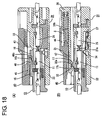
- the locking claw 32 of the lock arm 31 moves over the lock portion 17 and the lock arm 31 is resiliently at least partly restored to substantially engage the rear surface 32a of the locking claw 32 with the rear surface 17b of the lock portion 17 as shown in FIG. 18(B). At this time, the lock arm 31 is completely retracted from the space before the bulging portion 42.
- the slider 40 reaches a position where the pushable portions 46 are disengaged from the pushing portions 16 (pushed-state canceling position) to be completely freed from the pushed state. Thus, the slider 40 is permitted to move substantially along the moving direction MD.
- the biasing force of the compression coil spring S is released to move the slider 40 forward.
- the locking projections 47 come substantially into contact with the receiving portions 38, thereby preventing the slider 40 from moving any further forward.
- the bulging portion 42 is located above (i.e. on a deformation side of) the lock arm 31, thereby preventing the resilient deformation of the lock arm 31.
- the pushable portions 46 are caused to at least partly escape into the clearances between the pushing portions 16 and the reinforcing portions 15, they are returned to their natural states.
- the two housings 10, 20 may be separated for maintenance or other reason.
- the operating portion 43 of the slider 40 is manipulated or operated (pulled backward) to move the slider 40 backward from the initial position while compressing the compression coil spring S.
- the rear surfaces 46b of the pushable portions 46 come substantially into sliding contact with the rear surfaces 16b of the pushing portions 16, whereby the pushable portions 46 move onto the pushing portions 16 and the pushable arms 45 are resiliently deformed upward or outward.
- the bulging portion 42 is retracted from the deformation space for the lock arm 31.
- the locking claw 32 moves onto the lock portion 17 by being guided by the inclination of the rear surface 32a thereof and the lock arm 31 is resiliently deformed, with the result that the locked state of the two housings 10 20 is canceled (see FIG. 17 (B) ).
- the two housings 10, 20 can be separated by further pulling the slider 40 in this state.
- the slider 40 is moved forward and backward or substantially along the moving direction MD upon connecting and separating the two housings 10, 20 substantially along the connecting and separating directions CSD (the moving direction MD being preferably substantially parallel to the connecting and separating directions CSD).
- the entire slider 40 may be displaced upward to hinder its sliding movement.
- the upper surfaces 49a of the restricting portions 49 of the locking projections 47 are engageable with the upper edges 37a of the escaping grooves 37 at the front side of the slider 40, whereas the pressing portions 35a are engageable with the escaping portions 43a at the rear side of the slider 40.
- the upward displacement (i.e. the displacement in a direction intersecting the moving direction MD) of the slider 40 can be constantly restricted. This smoothes movements of the slider 40, thereby improving the connecting/separating operability.
- the one or more locking projections 47 are provided with the respective restricting portions 49 bulging more outward than the guiding surfaces 48a, and the upper surfaces 49a of the restricting portions 49 are to be engaged with the upper edges 37a of the escaping grooves 37 to restrict a displacement of the slider 40 along the direction intersecting with the moving direction MD of the slider 40.
- areas of engagement of the restricting portions 49 with the escaping grooves 37 can be increased by as much as the restricting portions 49 bulge out from the guiding surfaces 48a.
- the displacement of the slider 40 can be sufficiently restricted.
- a satisfactory assembling operability can be ensured for the slider 40 by providing the guiding surfaces 48a as before.
- the slider 40 is likely to undergo an upward displacement since being mounted on the lateral (upper) surface of the male housing 20, the displacement of the slider 40 can be securely restricted since the one or more restricting portions 49 are provided substantially at the side of or laterally from the locking projections 47 preferably substantially opposite from the upper surface of the male housing 20.
- a slider 40 movable along forward and backward directions or along a moving direction MD and a compression coil spring S (as a preferred biasing member) capable of accumulating a biasing force as the slider 40 is moved backward by being pushed by a female housing 10 in a connecting process are assembled into a male housing 20.
- the male housing 20 is provided with one or more escaping grooves 37 for at least partly escaping one or more respective locking projections 47 of the slider 40 and one or more receiving portions 38 engageable with the respective locking projections 47 to prevent the slider 40 from coming out.
- Each locking projection 47 preferably is formed with a guiding surface 48a for guiding a movement of the locking projection 47 over the receiving portion 38 when the slider 40 is assembled, and a restricting portion 49 for restricting an upward or outward displacement of the slider 40 by being engaged with an upper edge or edge portion 37a of the escaping groove 37.
- the restricting portions 49 preferably are so formed as to bulge more outward than the guiding surface 48a.
Landscapes
- Details Of Connecting Devices For Male And Female Coupling (AREA)
Applications Claiming Priority (2)
| Application Number | Priority Date | Filing Date | Title |
|---|---|---|---|
| JP2003351270A JP4179129B2 (ja) | 2003-10-09 | 2003-10-09 | コネクタ |
| JP2003351270 | 2003-10-09 |
Publications (2)
| Publication Number | Publication Date |
|---|---|
| EP1523072A1 true EP1523072A1 (fr) | 2005-04-13 |
| EP1523072B1 EP1523072B1 (fr) | 2006-11-29 |
Family
ID=34225354
Family Applications (1)
| Application Number | Title | Priority Date | Filing Date |
|---|---|---|---|
| EP04024108A Expired - Fee Related EP1523072B1 (fr) | 2003-10-09 | 2004-10-08 | Connecteur, système de connection et méthode d'assemblage |
Country Status (6)
| Country | Link |
|---|---|
| US (1) | US7008258B2 (fr) |
| EP (1) | EP1523072B1 (fr) |
| JP (1) | JP4179129B2 (fr) |
| KR (1) | KR101006943B1 (fr) |
| CN (1) | CN1288804C (fr) |
| DE (1) | DE602004003446T2 (fr) |
Cited By (1)
| Publication number | Priority date | Publication date | Assignee | Title |
|---|---|---|---|---|
| CN109702968A (zh) * | 2018-12-28 | 2019-05-03 | 深圳市凯中精密技术股份有限公司 | 内滑块机构、连接器脱膜装置及其脱膜方法 |
Families Citing this family (7)
| Publication number | Priority date | Publication date | Assignee | Title |
|---|---|---|---|---|
| JP5653150B2 (ja) * | 2010-09-16 | 2015-01-14 | 矢崎総業株式会社 | 半嵌合防止コネクタ |
| JP2014110182A (ja) * | 2012-12-03 | 2014-06-12 | Jst Mfg Co Ltd | 電気コネクタ、およびスクイブの接続装置 |
| JP5885096B2 (ja) * | 2013-05-08 | 2016-03-15 | 住友電装株式会社 | コネクタ |
| JP6287987B2 (ja) * | 2015-07-22 | 2018-03-07 | 住友電装株式会社 | コネクタ |
| JP6427146B2 (ja) * | 2016-07-29 | 2018-11-21 | 矢崎総業株式会社 | コネクタ |
| US10763615B2 (en) * | 2017-06-06 | 2020-09-01 | Nippon Tanshi Co., Ltd. | Connector structure having a longitudinal movement restricting protrusion |
| JP7230739B2 (ja) * | 2019-08-09 | 2023-03-01 | 住友電装株式会社 | コネクタ |
Citations (2)
| Publication number | Priority date | Publication date | Assignee | Title |
|---|---|---|---|---|
| US5993238A (en) * | 1996-12-19 | 1999-11-30 | Yazaki Corporation | Half-fitting prevention connector |
| EP1233480A1 (fr) * | 2001-02-16 | 2002-08-21 | Sumitomo Wiring Systems, Ltd. | Connecteur et méthode pour son assemblage |
Family Cites Families (5)
| Publication number | Priority date | Publication date | Assignee | Title |
|---|---|---|---|---|
| US5618201A (en) | 1994-06-14 | 1997-04-08 | Yazaki Corporation | Connector having engagement detecting device |
| JP3503729B2 (ja) * | 1996-11-08 | 2004-03-08 | 住友電装株式会社 | コネクタ |
| DE10159753B4 (de) | 2001-02-16 | 2004-03-18 | Sumitomo Wiring Systems, Ltd., Yokkaichi | Verbinder, Verbindergehäuse und Verfahren zum Zusammenbauen eines Verbinders |
| DE10159196B4 (de) | 2001-02-16 | 2004-02-05 | Sumitomo Wiring Systems, Ltd., Yokkaichi | Verbinder |
| DE10159177B4 (de) | 2001-02-16 | 2004-08-19 | Sumitomo Wiring Systems, Ltd., Yokkaichi | Verbinder und Verfahren zum Zusammenbauen eines Verbinders |
-
2003
- 2003-10-09 JP JP2003351270A patent/JP4179129B2/ja not_active Expired - Fee Related
-
2004
- 2004-10-07 US US10/960,861 patent/US7008258B2/en not_active Expired - Fee Related
- 2004-10-08 EP EP04024108A patent/EP1523072B1/fr not_active Expired - Fee Related
- 2004-10-08 DE DE602004003446T patent/DE602004003446T2/de active Active
- 2004-10-09 CN CNB2004100835360A patent/CN1288804C/zh not_active Expired - Fee Related
- 2004-10-09 KR KR1020040080690A patent/KR101006943B1/ko not_active IP Right Cessation
Patent Citations (2)
| Publication number | Priority date | Publication date | Assignee | Title |
|---|---|---|---|---|
| US5993238A (en) * | 1996-12-19 | 1999-11-30 | Yazaki Corporation | Half-fitting prevention connector |
| EP1233480A1 (fr) * | 2001-02-16 | 2002-08-21 | Sumitomo Wiring Systems, Ltd. | Connecteur et méthode pour son assemblage |
Cited By (2)
| Publication number | Priority date | Publication date | Assignee | Title |
|---|---|---|---|---|
| CN109702968A (zh) * | 2018-12-28 | 2019-05-03 | 深圳市凯中精密技术股份有限公司 | 内滑块机构、连接器脱膜装置及其脱膜方法 |
| CN109702968B (zh) * | 2018-12-28 | 2024-01-30 | 深圳市凯中精密技术股份有限公司 | 内滑块机构、连接器脱膜装置及其脱膜方法 |
Also Published As
| Publication number | Publication date |
|---|---|
| KR20050034565A (ko) | 2005-04-14 |
| US20050054233A1 (en) | 2005-03-10 |
| KR101006943B1 (ko) | 2011-01-12 |
| EP1523072B1 (fr) | 2006-11-29 |
| CN1606197A (zh) | 2005-04-13 |
| US7008258B2 (en) | 2006-03-07 |
| DE602004003446D1 (de) | 2007-01-11 |
| DE602004003446T2 (de) | 2007-09-27 |
| CN1288804C (zh) | 2006-12-06 |
| JP2005116413A (ja) | 2005-04-28 |
| JP4179129B2 (ja) | 2008-11-12 |
Similar Documents
| Publication | Publication Date | Title |
|---|---|---|
| US7097503B2 (en) | Connector and a method of disassembling it | |
| EP1560298B1 (fr) | Connecteur cloisonné et montage de connecteurs | |
| EP1054481B1 (fr) | Un connecteur | |
| US6743040B1 (en) | Connector and a connector assembly | |
| US7118426B2 (en) | Connector with reinforced retainer mount hole | |
| US7059902B2 (en) | Connector, a connector assembly and a method of assembling a connector assembly | |
| EP0993077A2 (fr) | Connecteur pour empêcher une demi-connexion et son procédé de fabrication | |
| EP1233480B1 (fr) | Connecteur et méthode pour son assemblage | |
| EP2315320A1 (fr) | Connecteur et son procédé d'assemblage | |
| US6786754B2 (en) | Connector and a connector assembly | |
| US20070141905A1 (en) | Connector | |
| EP1523072B1 (fr) | Connecteur, système de connection et méthode d'assemblage | |
| EP1557908A2 (fr) | Un connecteur | |
| US6561833B2 (en) | Connector and a method for assembling a connector | |
| US20040106330A1 (en) | Connector | |
| US6551146B2 (en) | Connector and a method for assembling a connector | |
| US7377824B2 (en) | Connector and connector assembly | |
| US7074069B2 (en) | Connector and a connector assembly | |
| US20030186579A1 (en) | Connector and a connector assembly | |
| US6953364B2 (en) | Connector, a shorting terminal and a method of assembling it | |
| US6530800B2 (en) | Connector and method for assembling a connector | |
| US6666710B2 (en) | Connector and a connector assembly | |
| US6488547B2 (en) | Connector with longitudinally spaced locks for retaining terminal fittings | |
| JP3476071B2 (ja) | コネクタ |
Legal Events
| Date | Code | Title | Description |
|---|---|---|---|
| PUAI | Public reference made under article 153(3) epc to a published international application that has entered the european phase |
Free format text: ORIGINAL CODE: 0009012 |
|
| 17P | Request for examination filed |
Effective date: 20041021 |
|
| AK | Designated contracting states |
Kind code of ref document: A1 Designated state(s): AT BE BG CH CY CZ DE DK EE ES FI FR GB GR HU IE IT LI LU MC NL PL PT RO SE SI SK TR |
|
| AX | Request for extension of the european patent |
Extension state: AL HR LT LV MK |
|
| AKX | Designation fees paid |
Designated state(s): DE FR HU |
|
| GRAP | Despatch of communication of intention to grant a patent |
Free format text: ORIGINAL CODE: EPIDOSNIGR1 |
|
| GRAS | Grant fee paid |
Free format text: ORIGINAL CODE: EPIDOSNIGR3 |
|
| GRAA | (expected) grant |
Free format text: ORIGINAL CODE: 0009210 |
|
| AK | Designated contracting states |
Kind code of ref document: B1 Designated state(s): DE FR HU |
|
| REF | Corresponds to: |
Ref document number: 602004003446 Country of ref document: DE Date of ref document: 20070111 Kind code of ref document: P |
|
| ET | Fr: translation filed | ||
| REG | Reference to a national code |
Ref country code: HU Ref legal event code: AG4A Ref document number: E001649 Country of ref document: HU |
|
| PLBE | No opposition filed within time limit |
Free format text: ORIGINAL CODE: 0009261 |
|
| STAA | Information on the status of an ep patent application or granted ep patent |
Free format text: STATUS: NO OPPOSITION FILED WITHIN TIME LIMIT |
|
| 26N | No opposition filed |
Effective date: 20070830 |
|
| PGFP | Annual fee paid to national office [announced via postgrant information from national office to epo] |
Ref country code: FR Payment date: 20131009 Year of fee payment: 10 Ref country code: DE Payment date: 20131002 Year of fee payment: 10 |
|
| PGFP | Annual fee paid to national office [announced via postgrant information from national office to epo] |
Ref country code: HU Payment date: 20130913 Year of fee payment: 10 |
|
| REG | Reference to a national code |
Ref country code: DE Ref legal event code: R119 Ref document number: 602004003446 Country of ref document: DE |
|
| PG25 | Lapsed in a contracting state [announced via postgrant information from national office to epo] |
Ref country code: DE Free format text: LAPSE BECAUSE OF NON-PAYMENT OF DUE FEES Effective date: 20150501 |
|
| REG | Reference to a national code |
Ref country code: FR Ref legal event code: ST Effective date: 20150630 |
|
| PG25 | Lapsed in a contracting state [announced via postgrant information from national office to epo] |
Ref country code: HU Free format text: LAPSE BECAUSE OF NON-PAYMENT OF DUE FEES Effective date: 20141009 Ref country code: FR Free format text: LAPSE BECAUSE OF NON-PAYMENT OF DUE FEES Effective date: 20141031 |