EP2315320A1 - Connecteur et son procédé d'assemblage - Google Patents
Connecteur et son procédé d'assemblage Download PDFInfo
- Publication number
- EP2315320A1 EP2315320A1 EP11001223A EP11001223A EP2315320A1 EP 2315320 A1 EP2315320 A1 EP 2315320A1 EP 11001223 A EP11001223 A EP 11001223A EP 11001223 A EP11001223 A EP 11001223A EP 2315320 A1 EP2315320 A1 EP 2315320A1
- Authority
- EP
- European Patent Office
- Prior art keywords
- terminal
- shorting
- connector housing
- shorting terminal
- contact
- Prior art date
- Legal status (The legal status is an assumption and is not a legal conclusion. Google has not performed a legal analysis and makes no representation as to the accuracy of the status listed.)
- Withdrawn
Links
Images


Classifications
-
- H—ELECTRICITY
- H01—ELECTRIC ELEMENTS
- H01R—ELECTRICALLY-CONDUCTIVE CONNECTIONS; STRUCTURAL ASSOCIATIONS OF A PLURALITY OF MUTUALLY-INSULATED ELECTRICAL CONNECTING ELEMENTS; COUPLING DEVICES; CURRENT COLLECTORS
- H01R13/00—Details of coupling devices of the kinds covered by groups H01R12/70 or H01R24/00 - H01R33/00
- H01R13/66—Structural association with built-in electrical component
- H01R13/70—Structural association with built-in electrical component with built-in switch
- H01R13/703—Structural association with built-in electrical component with built-in switch operated by engagement or disengagement of coupling parts, e.g. dual-continuity coupling part
- H01R13/7031—Shorting, shunting or bussing of different terminals interrupted or effected on engagement of coupling part, e.g. for ESD protection, line continuity
- H01R13/7032—Shorting, shunting or bussing of different terminals interrupted or effected on engagement of coupling part, e.g. for ESD protection, line continuity making use of a separate bridging element directly cooperating with the terminals
-
- H—ELECTRICITY
- H01—ELECTRIC ELEMENTS
- H01R—ELECTRICALLY-CONDUCTIVE CONNECTIONS; STRUCTURAL ASSOCIATIONS OF A PLURALITY OF MUTUALLY-INSULATED ELECTRICAL CONNECTING ELEMENTS; COUPLING DEVICES; CURRENT COLLECTORS
- H01R13/00—Details of coupling devices of the kinds covered by groups H01R12/70 or H01R24/00 - H01R33/00
- H01R13/58—Means for relieving strain on wire connection, e.g. cord grip, for avoiding loosening of connections between wires and terminals within a coupling device terminating a cable
- H01R13/5804—Means for relieving strain on wire connection, e.g. cord grip, for avoiding loosening of connections between wires and terminals within a coupling device terminating a cable comprising a separate cable clamping part
-
- H—ELECTRICITY
- H01—ELECTRIC ELEMENTS
- H01R—ELECTRICALLY-CONDUCTIVE CONNECTIONS; STRUCTURAL ASSOCIATIONS OF A PLURALITY OF MUTUALLY-INSULATED ELECTRICAL CONNECTING ELEMENTS; COUPLING DEVICES; CURRENT COLLECTORS
- H01R13/00—Details of coupling devices of the kinds covered by groups H01R12/70 or H01R24/00 - H01R33/00
- H01R13/62—Means for facilitating engagement or disengagement of coupling parts or for holding them in engagement
- H01R13/627—Snap or like fastening
- H01R13/6271—Latching means integral with the housing
- H01R13/6272—Latching means integral with the housing comprising a single latching arm
Definitions
- the present invention relates to a shorting terminal, a connector and to an assembling method therefor.
- FIG. 1 An example of a connector provided with a shorting terminal is known from Japanese Unexamined Patent Publication No. H09-153386 .
- This connector is constructed such that a plurality of terminal fittings and a shorting terminal are accommodated in a connector housing, and the corresponding terminal fittings are shorted by the shorting terminal.
- the shorting terminal includes touching pieces capable of touching the terminal fittings and a pair of contact piece to be pushed by a jig upon accommodating the shorting terminal into the connector housing.
- Such a shorting terminal is mounted into the connector housing by an automatic machine in some cases and, in such a case, the mounting operation is automatically stopped when the shorting terminal is pushed by a specified stroke.
- the above contact pieces are formed by bending plate surfaces of the shorting terminal, and the jig is pressed against the plate surfaces of the contact pieces.
- the contact pieces are inclined to be deformed by a pushing force. Therefore, even if the shorting terminal is pushed by the specified stroke by the automatic machine, it might be mounted at a position located before a proper position.
- the present invention was developed in view of the above situation and an object thereof is to enable a shorting terminal to be mounted at a proper position in a connector housing.
- a shorting terminal to be at least partly accommodated in a connector housing to short corresponding ones of a plurality of terminal fittings at least partly accommodated in the connector housing, comprising:
- the shorting terminal is formed with the supporting piece held engaged with the contact piece from the side opposite to the push-in direction into the connector housing, the contact piece can be prevented from being inclined and deformed by being supported by the supporting piece when a jig is pressed against the contact piece. Accordingly, upon accommodating the shorting terminal into the connector housing, the shorting terminal can be correctly accommodated at a proper position if being pushed by a specified (predetermined or predeterminable) stroke, wherefore the shorting terminal can be easily mounted particularly using an automatic machine.
- the contact piece is formed by bending and the supporting piece is formed by bending and held in contact with the contact piece from a side substantially opposite to the push-in direction into the connector housing.
- the shorting terminal further comprises at least one pair of resiliently deformable touching pieces which can touch the corresponding terminal fittings so as to be able to short the terminal fittings.
- the contact piece and/or the supporting piece are so arranged as to be able to prevent excessive resilient deformations of the touching pieces by coming into contact with the touching pieces.
- the contact piece and the supporting piece are so arranged as to be able to prevent excessive resilient deformations of the touching pieces by the contact of the contact piece and the supporting piece with the touching pieces, satisfactory resilient forces can be maintained for the touching pieces even if the shorting terminal is repeatedly used.
- the plate surfaces of the contact piece and those of the supporting piece cross at an angle different from 0° or 180°, preferably substantially at right angles to each other, and crossing end portions of the contact piece and the supporting piece are interlocked by the engagement of one or more projections and recesses.
- the plate surfaces of the contact piece and those of the supporting piece cross at an angle different from 0° or 180°, preferably substantially at right angles to each other and the crossing end portions of the contact piece and the supporting piece are or can be interlocked by the engagement of projections and recesses, a supporting force by the supporting piece can be increased and the deformation of the contact piece can be more reliably prevented.
- the jig can be operated on the supporting piece in a direction normal to the push-in direction acting on the supporting piece and it becomes possible to use the supporting piece as the contact piece and the contact piece as the supporting piece. In other words, even a case where the mounting direction of the shorting terminal into the connector housing is a direction at an angle different from 0° or 180°, preferably substantially normal to the push-in direction acting on the contact piece can be dealt with.
- the shorting terminal further comprising at least one locking piece to lock the terminal fitting into the connector housing, wherein the locking piece extends obliquely to the inserting direction of the terminal fitting into a shorting terminal accommodating chamber of the connector housing.
- the shorting terminal further comprises a shorting terminal main body being formed with one or more beveled portions by having one or more corner portions of a front end with respect to the inserting direction obliquely cut, so that the insertion of the shorting terminal is guided by these beveled portions.
- a connector comprising:
- a connector comprising:
- the shorting terminal is formed with the supporting piece held in contact with the contact piece from the side opposite to the push-in direction into the connector housing, the contact piece can be prevented from being inclined and deformed by being supported by the supporting piece when a jig is pressed against the contact piece. Accordingly, upon accommodating the shorting terminal into the connector housing, the shorting terminal can be correctly accommodated at a proper position if being pushed by a specified stroke, wherefore the shorting terminal can be easily mounted using an automatic machine.
- the shorting terminal is formed with a pair of resiliently deformable touching pieces which touch the corresponding terminal fittings so as to be able to short the terminal fittings, and the contact piece and the supporting piece are so arranged as to be able to prevent excessive resilient deformations of the touching pieces by coming into contact with the touching pieces.
- the contact piece and the supporting piece are so arranged as to be able to prevent excessive resilient deformations of the touching pieces by the contact of the contact piece and the supporting piece with the touching pieces, satisfactory resilient forces can be maintained for the touching pieces even if the shorting terminal is repeatedly used.
- the plate surfaces of the contact piece and those of the supporting piece cross at right angles to each other, and crossing end portions of the contact piece and the supporting piece are interlocked by the engagement of projections and recesses.
- the jig can be operated on the supporting piece in a direction normal to the push-in direction acting on the supporting piece and it becomes possible to use the supporting piece as the contact piece and the contact piece as the supporting piece. In other words, even a case where the mounting direction of the shorting terminal into the connector housing is a direction normal to the push-in direction acting on the contact piece can be dealt with.
- the shorting terminal is formed with a pair of resiliently deformable touching pieces which touch the corresponding terminal fittings so as to be able to short the terminal fittings
- a mating connector housing connectable with the connector housing includes a disengaging portion projecting therefrom and capable of coming into contact with at least either one of the two touching pieces as the two connector housings are connected, thereby resiliently deforming the touching pieces held in contact therewith in such a direction as to cancel the shorted state
- the disengaging portion includes a rib extending in a connecting direction of the two connector housings.
- the disengaging portion With the miniaturization of the connector, the disengaging portion becomes narrower and the strength thereof might become insufficient. However, if the disengaging portion includes the rib extending in the connecting direction, the shortage of strength of the disengaging portion can be compensated for.
- a shorting terminal to be accommodated in a connector housing to short corresponding ones of a plurality of terminal fittings accommodated in the connector housing, comprising:
- the shorting terminal is formed with the supporting piece held in contact with the contact piece from the side opposite to the push-in direction into the connector housing, the contact piece can be prevented from being inclined and deformed by being supported by the supporting piece when a jig is pressed against the contact piece. Accordingly, upon accommodating the shorting terminal into the connector housing, the shorting terminal can be correctly accommodated at a proper position if being pushed by a specified stroke, wherefore the shorting terminal can be easily mounted using an automatic machine.
- the shorting terminal is formed with at least one pair of resiliently deformable touching pieces which can touch the corresponding terminal fittings so as to be able to short the terminal fittings
- a mating connector housing connectable with the connector housing includes at least one disengaging portion projecting therefrom and capable of coming into contact with at least part of the plurality touching pieces as the two connector housings are connected, thereby resiliently deforming the touching pieces held in contact therewith in such a direction as to cancel the shorted state.
- the disengaging portion includes at least one rib extending in the connecting direction of the two connector housings.
- At least part of the disengaging portions includes at least one first rib between two disengagement guiding surfaces and/or one or more second ribs preferably paired in width direction at positions at least partly vertically overlapping with the two disengagement guiding surfaces in height direction.
- lateral shaking movements of the touching pieces are substantially prevented by the first ribs.
- At least one wire pressing member is so formed in or on the connector housing as to communicate with the cavities, wherein the wire pressing member has one or more projections and can prevent loose movements of wires in cavities of the connector housing by being at least partly inserted into the accommodating chamber to cause the respective projections to engage or bite into the wires.
- a method of assembling or mounting a connector comprising:
- the contact piece is formed by bending and the supporting piece is formed by bending and held in contact with the contact piece from a side substantially opposite to the push-in direction into the connector housing.
- a connector of this embodiment is provided with a shorting terminal 10, terminal fittings 40, a connector housing 50 and preferably a retainer 80.
- Each terminal fitting 40 is formed of an electrically conductive (preferably metal) plate material preferably into a male terminal fitting provided with a tab portion 41 at or near its front end, a wire connection portion (preferably comprising at least one barrel portion 42) at or near its rear end and a terminal main portion 43 at its intermediate part as shown in FIG. 2 .
- the tab portion 41 is to be connected with a mating female terminal fitting 90 by being at least partly inserted into a box or tube portion 91 of the mating female terminal fitting 90, and the wire connection portion (preferably the barrel portion 42) is connectable with a wire 45 (preferably by being crimped or bent or folded into connection) with an end of the wire 45.
- the terminal main portion 43 has a substantially tubular shape with open front and rear sides, and at least one (preferably metal) locking portion 46 is provided or formed preferably by making at least one cut in a surrounding wall of the terminal main portion 43 and bending the cut part outward.
- the connector housing 50 is made e.g. of a synthetic resin material and preferably is a male connector housing connectable with and separable from a mating female connector housing 30 as shown in FIG. 1 .
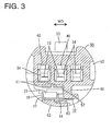
- this connector housing 50 is shaped to be narrow and long in forward and backward directions FBD (connecting and separating directions CSD) and includes a block-shaped terminal accommodating portion 51 and a substantially tubular receptacle 52 projecting forward from or at or on (preferably the peripheral edge of the front end of) the terminal accommodating portion 51.
- FBD forward and backward directions CSD
- the outer peripheral edges of the lower halves of these terminal accommodating portions 51 and the receptacle 52 preferably have substantially arcuate shapes (see FIG. 3 ).
- a substantially flat horizontal surface (or a substantially flat surface containing the forward and backward directions FBD and/or connecting and separating directions CSD) is formed on the outer surface of the lateral (upper) wall of the receptacle 52, and at least one lock portion 53 projects from this (horizontal) surface.
- a lock arm 31 resiliently deformably formed in the mating female connector housing 30 is resiliently engaged or enageable with the lock portion 53, whereby the two connector housings 10, 30 are or can be locked in their connected state.
- a connection detecting member 33 for detecting whether or not the two connector housings 10, 30 are connected by being permitted to move only when the two connector housings 10, 30 are properly connected is so arranged preferably as to be movable (preferably slidable) on the lateral (upper) surface of the lock arm 31 substantially in forward and backward directions FBD.
- a stepped or recessed terminal receiving portion 55 for receiving the (metal) locking portion 46 preferably is formed in an inner wall of each cavity 54, and the terminal fitting 40 is prevented from coming out of the cavity 54 by the resilient engagement of the metal locking portion 46 with the terminal receiving portion 55.
- Out of the terminal fitting 40, the terminal main portion 43 and the wire connection portion are at least partly accommodated in the cavity 54 and the tab portion 41 projects into the receptacle 52.
- An end part of the wire 45 extends substantially in forward and backward directions FBD in the cavity 54 and the other part is drawn to the outside through the (preferably rear) end opening of the cavity 54.
- a retainer mount hole 56 communicating with the respective cavities 54 preferably substantially in width direction WD is formed in one outer side surface of the terminal accommodating portion 51, and a retainer main body 81 of the retainer 80 is at least partly insertable in an insertion direction (preferably substantially sideways and/or in a direction at an angle different from 0° or 180°, preferably substantially normal to the forward and backward directions FBD) into this retainer mount hole 56.
- the retainer 80 is movable between a partial locking position (as a preferred first position) and a full locking position (as a preferred second position), wherein the insertion and withdrawal of the terminal fittings 40 into and from the cavities 54 are permitted at the partial locking position and the retainer 80 is engaged with the terminal fittings 40 at least partly inserted into the cavities 54 to retain the terminal fittings 40 at the full locking position so as to lock them into the cavities 54.
- a wire pressing portion 82 preferably is movably (preferably openably and closably) connected with the retainer 80 via at least one hinge 83.
- one or more (preferably sawtooth-shaped) projections 84 formed on the wire pressing portion 82 are pressed against the insulation coatings of the wires 45 to engage them and/or to bite or cut thereinto, whereby loose movements of the wires 45 in the cavities 54 can be prevented.
- a shorting terminal accommodating chamber 57 is formed in (preferably the outer side surface of) the terminal accommodating portion 51 preferably where the retainer mount hole 56 is formed. More specifically, the shorting terminal accommodating chamber 57 is arranged adjacent to (preferably substantially below) at least one pair of adjacent cavities 54, wherein a front (preferably upper or inner) part thereof communicates with the two cavities 54, the front surface thereof makes an opening in (preferably the front surface of) the terminal accommodating portion 51 (back surface of the receptacle 52), and the shorting terminal accommodating chamber 57 preferably extends substantially in forward and backward directions FBD substantially in parallel with the two cavities 54.
- the shorting terminal 10 is at least partly inserted into the shorting terminal accommodating chamber 57 sideways (direction at an angle different from 0° or 180°, preferably substantially normal to the connecting and separating directions CSD of the two connector housings 10, 30) through a (preferably lateral) opening preferably by an automatic machine, and mounted such that the front end thereof (leading ends of touching pieces 11 to be described later) is at least partly located in the receptacle 52 through the opening in (preferably the front surface of) the terminal accommodating portion 54.
- the lateral opening made by the shorting terminal accommodating chamber 57 is at least partly closed by a closing plate 89 of the retainer 80 as the retainer 80 reaches the full locking position, whereby the shorting terminal 10 is protected (see FIG. 6 ).
- the above retainer mount hole 56 is arranged behind and/or slightly above (or displaced of) the shorting terminal accommodating chamber 57.
- the rear end of the outer circumferential surface of the terminal accommodating portion 51 is recessed to form a retainer fitting portion 58, into which an outer frame 85 of the retainer 80 is or can be at least partly mounted, and a rear partition wall 59 at least partly defining the shorting terminal accommodating chamber 57 is provided between the retainer mount hole 56 and the retainer fitting portion 58. As shown in FIG.
- the shorting terminal accommodating chamber 57 preferably is also defined by a side partition wall 61 hanging down at a position slightly displaced from the widthwise center of the terminal accommodating portion 51 toward a side opposite to the lateral opening and also by a bottom or additional wall 62 of the terminal accommodating portion 51.
- a side partition wall 61 hanging down at a position slightly displaced from the widthwise center of the terminal accommodating portion 51 toward a side opposite to the lateral opening and also by a bottom or additional wall 62 of the terminal accommodating portion 51.
- In the bottom surface of the shorting terminal accommodating chamber 57 is formed at least one locking groove 63 for the shorting terminal 10 extending substantially in width direction WD to the side opposite to the lateral opening below and across the side partition wall 61.
- mount guiding groove 64 for the shorting terminal 10 extending substantially in width direction WD preferably substantially along a boundary to the receptacle 52.
- a bottom wall 66 of the receptacle 52 preferably has a part thicker than the bottom wall 62 of the terminal accommodating portion 51, so that the height of the inner (upper) surface of the bottom wall 66 of the receptacle 52 is higher or more inward than the bottom surface of the shorting terminal accommodating chamber 57 in this part.
- An escaping recess 67, into which the leading ends of the touching pieces 11 are or can be at least partly inserted upon the action of the shorting terminal 10 is formed in the inner upper surface of the bottom wall 66 of the receptacle 52.
- the bottom surface of this escaping recess 67 preferably is set substantially at the same height or radial position as the bottom surface of the shorting terminal accommodating chamber 57.
- the shorting terminal 10 is formed of an electrically conductive (preferably metal) plate material and includes a shorting terminal main body 12 (preferably substantially in the form of a flat plate) to be substantially horizontally arranged substantially along the bottom surface of the shorting terminal accommodating chamber 57 and at least one pair of touching pieces 11 projecting from (preferably the rear ends of) the shorting terminal main body 12 as shown in FIGS. 4 and 5 .
- a shorting terminal main body 12 preferably substantially in the form of a flat plate
- a pair of touching pieces 11 projecting from (preferably the rear ends of) the shorting terminal main body 12 as shown in FIGS. 4 and 5 .
- At lest one (preferably substantially U- or gate-shaped) slit 13 is formed in the shorting terminal main body 12, and a locking piece 14 is formed by bending a plate piece at least partly enclosed or defined by the slit 13.
- the locking piece 14 extends obliquely to an inserting direction ID into the shorting terminal accommodating chamber 57, is resiliently deformably, resiliently comes substantially into sliding contact with the back surface of the locking groove 63 in the mounting process of the shorting terminal 10, and is at least partly fitted into the locking groove 63 as the shorting terminal 10 is properly mounted.
- the shorting terminal main body 12 preferably is formed with one or more beveled portions 15 by having the opposite corner portions of one lateral end (front end with respect to the inserting direction ID into the shorting terminal accommodating chamber 57) obliquely cut, and is easily insertable or guided into the shorting terminal accommodating chamber 57 by these beveled portions 15.
- the two touching pieces 11 are arranged preferably in an eccentric manner toward the other lateral end (rear end in the inserting direction ID into the shorting terminal accommodating chamber 57) of the rear end of the shorting terminal main body 12, and are resiliently brought or bringable into contact with the respective terminal fittings 40 at least partly accommodated in the respective (e.g. the middle and left) cavities 54 in FIG. 3 .
- the touching pieces 11 are in the form of cantilevers folded substantially back at or near the rear end of the shorting terminal main body 12 to extend substantially forward, are resiliently displaceable upward and downward (or toward and away from the portion of the shorting terminal main body 12 to be arranged substantially along the respective (bottom) surface of the shorting terminal accommodating chamber 57) and include pointed or mountain-shaped touching portions 16 bent at or near the leading ends of the touching pieces 11.
- the leading ends of the two touching pieces 11 at least partly project into the receptacle 52, and the touching portions 16 can be resiliently brought into contact with (preferably the lower surfaces of the tab portions 41 of) the corresponding terminal fittings 40.
- At least one of the two touching pieces 11 is resiliently deformed in a disengaging direction (downward) by at least one disengaging portion 38 formed in the mating female connector housing 30 as the two connector housings 10, 30 are connected, thereby separating the touching portions 16 from the tab portions 41.
- the shorting terminal main body 12 is formed with at least one contact piece 17 preferably by bending, which is pushed in by a jig or the like at the time of insertion into the shorting terminal accommodating chamber 57.
- the contact piece 17 is located at or near the front end of the other end (rear end in the inserting direction ID into the shorting terminal accommodating chamber 57) of the shorting terminal main body 12 and is formed into a vertical or angled wall by bending a plate piece substantially horizontally projecting sideways from the other end of this shorting terminal main body 12 at an angle different from 0° or 180°, preferably substantially normal or upward, and/or is located at a slightly inner side upon being bent by having one or more slits 18.
- This contact piece 17 is arranged at such a position as to at least partly overlap with the right touching piece 11 in width direction WD in FIG. 5 , thereby being located in the resilient deformation range of this touching piece 11.
- the plate surface of the contact piece 17 is set to extend substantially in forward and backward directions FBD (directions at an angle different from 0° or 180°, preferably substantially normal to the inserting direction ID into the shorting terminal accommodating chamber 57), and/or the length of this contact piece 17 in forward and backward directions FBD preferably is less than about half, more preferably is slightly shorter than about 1/3 of the entire length of the shorting terminal main body 12.
- the outer plate surface serves as a pushable surface 19, against which the jig is to be pressed, and preferably extends substantially vertically or at an angle different from 0° or 180°, preferably substantially normal to the inserting direction ID.
- the shorting terminal main body 12 is also formed with at least one supporting piece 21 preferably by bending and/or embossing, the supporting piece 21 being held in contact and engaged with the contact piece 17, preferably with the inner one (surface opposite to and/or facing the pushable surface 19 in the inserting direction ID into the shorting terminal accommodating chamber 57) of the substantially opposite inner and outer plate surfaces of the contact piece 17.
- the supporting piece 21 is located at a position near the other end (rear end in the inserting direction into the shorting terminal accommodating chamber 57) of the front end of the shorting terminal main body 12 and formed into a vertical or angled wall substantially at an angle different from 0° or 180°, preferably substantially at right angles to the contact piece 17 preferably by bending a plate piece horizontally projecting forward from the front end of the shorting terminal main body 12 upward substantially at right angles.
- the supporting piece 21 can be located at a slightly inner side by having one or more slits 18 adjacent thereto, preferably at the opposite sides.
- the plate surfaces of the supporting piece 21 are set to extend substantially along width direction WD (inserting direction ID into the shorting terminal accommodating chamber 57), and the length of the supporting piece 21 in width direction WD preferably is about 1/2 of the width of the shorting terminal main body 12 and/or longer than the length of the contact piece 17 in forward and backward directions FBD.
- This supporting piece 21 is arranged to at least partly overlap with the both touching pieces 11 in width direction within the resilient deformation ranges of the both touching pieces 11.
- the supporting piece 21 and the contact piece 17 are engaged by one or more interlocking projections and recesses on the lateral edges facing each other (intersecting end portions), and the plate surfaces thereof cross at an angle different from 0° or 180°, preferably substantially at right angles to preferably be substantially L-shaped in plan view as a whole.
- a projection 23 formed on the upper or distal portion (preferably substantially the upper half) of one lateral edge of the supporting piece 21 is substantially aligned with and/or fitted into a cutout recess formed in the corresponding upper or distal portion (preferably substantially in the upper half) of one lateral edge of the contact piece 17 and a projection 24 formed on the lower portion (preferably on the lower half) of the lateral edge of the contact piece 17 is substantially aligned with and/or fitted into a cutout recess formed in the corresponding lower portion (preferably substantially the lower half) of the lateral edge of the supporting piece 21.
- the supporting piece 21 and the contact piece 17 stand up preferably with the substantially same projecting amount, so that the upper ends thereof substantially are horizontally aligned.
- the shorting terminal 10 preferably is at least partly accommodated first, but the terminal fittings 40 may be conversely accommodated first.
- the connector housing 50 and the shorting terminal 10 are set preferably in the automatic machine and/or substantially positioned with respect to each other and, then, the shorting terminal 10 is at least partly accommodated into the shorting terminal accommodating chamber 57 of the connector housing 50 in the inserting direction ID (preferably substantially sideways) preferably by the automatic machine.
- the jig of the automatic machine pushes or engages the pushable surface 19 of the contact piece 17 to push or displace the shorting terminal 10 in substantially straight in the width direction WD (direction along the plate surfaces of the supporting piece 21).
- a pushing force stress
- this pushing force preferably is distributed also to the supporting piece 21 supporting the contact piece 17 at the rear side opposite to the pushable surface 19 of the contact piece 17, therefore not being concentrated only on the contact piece 17.
- the pushing operation is automatically stopped when the shorting terminal 10 is pushed by a specified (predetermined or predeterminable) stroke by the automatic machine. If the shorting terminal 10 reaches a substantially proper mount position in this way, the locking piece 14 is resiliently engaged with the back surface of the locking groove 63 to retain the shorting terminal 10. Further, the locking piece 14 is engaged with the side surface of the locking groove 63 and the front end of the shorting terminal main body 12 is (preferably substantially closely) fitted into the mount guiding groove 64, whereby shaking movements of the shorting terminal 10 in width direction WD can be prevented. In this state, the both touching pieces 11 at least partly cross the interior of the shorting terminal accommodating chamber 57 obliquely forward and preferably are arranged such that the touching portions 16 are located at such height corresponding to the front positions of the two cavities 54.
- the both touching pieces 11 are pressed downward (substantially toward the shorting terminal main body 12) lest the touching pieces 11 should interfere with the opening edge of the lateral opening of the shorting terminal accommodating chamber 57 to prevent the inserting operation of the shorting terminal 10.
- the lower surfaces of the touching pieces 11 come into contact with at least either one of the contact piece 17 and the supporting piece 21, thereby preventing the touching pieces 11 from being pressed any further downward.
- the retainer 80 is held at the partial locking position (first position) and the terminal fittings 40 connected with the ends of the wires 45 are at least partly inserted into the corresponding cavities 54 from the insertion side, preferably substantially from behind.
- the tab portions 41 come into contact with the touching portions 16 of the shorting terminal 10 upon projecting into the receptacle 52, with the result that the touching pieces 11 are pressed downward or away from the terminal fittings 40.
- the terminal fittings 40 substantially properly inserted into the cavities 54 are primarily locked by the (metal) locking portions 46 while being resiliently held in contact with the touching portions 16 preferably at the base ends of the tab portions 41.
- the retainer 80 is moved to the full locking position (second position)
- the terminal fittings 40 are (preferably secondarily) locked by the retainer main body 81. In this state, the two terminal fittings 40 are shorted by the two touching pieces 11 of the shorting terminal 10 and there is no potential difference between the two terminal fittings 40.
- the both touching pieces 11 are pressed down or away from the terminal fittings 40 by the at least one disengaging portion 38 of the mating female connector housing 30 and the touching portions 16 are separated from the terminal fittings 40 (preferably from the tab portions 41 thereof) to cancel the shorted state of the two terminal fittings 40.
- the shorting terminal 10 preferably is formed with the at least one supporting piece 21 held in contact with the contact piece 17 from the side substantially opposite to the push-in direction (inserting direction ID) into the shorting terminal accommodating chamber 57.
- the contact piece 17 can be prevented from being inclined and/or deformed in the push-in direction ID by being supported from the rear side by the supporting piece 21. Accordingly, upon accommodating the shorting terminal 10 into the connector housing 50, the shorting terminal 10 can be substantially correctly accommodated at a proper position only if being pushed by the specified (predetermined or predeterminable) stroke by the automatic machine.
- the contact piece 17 and the supporting piece 21 preferably are so arranged as to be able to prevent excessive resilient deformations of the touching pieces 11 by the contact with the touching pieces 11, the excessive resilient deformations of the touching pieces 11 can be prevented and satisfactory resilient forces can be ensured for the touching pieces 11 even if the shorting terminal 10 is repeatedly used.
- the plate surfaces of the contact piece 17 and those of the supporting piece 21 preferably cross at an angle different from 0° or 180°, preferably substantially at right angles to each other and the crossing end portions preferably are interlocked by the engagement of the one or more recesses and one or more projections, a supporting force by the supporting piece 21 is increased and the deformation of the contact piece 17 caused by the contact with the jig can be more reliably prevented.
- the mounting direction of the shorting terminal 10 into the connector housing 50 is a direction substantially normal to width direction, which is the push-in direction on the contact piece 17, e.g. a forward direction (direction extending from the opening side of the receptacle toward the back side thereof), can be dealt with.
- a connector is provided with a plurality of terminal fittings 40, a shorting terminal 10 for shorting corresponding terminal fittings 40, and a connector housing 50 for at least partly accommodating the terminal fittings 40 and the shorting terminal 10.
- the shorting terminal 10 includes at least one contact piece 17 (preferably formed by bending) and engaged or pushed at the time of insertion into the connector housing 50 and at least one supporting piece 21 (preferably formed by bending) and engageable or held in contact with the respective contact piece(s) 17 to support it preferably from a side substantially opposite to a push-in direction ID into the connector housing 50.
- the contact piece 17 When a jig for pushing the shorting terminal 10 is pressed against a pushable surface 19 of the contact piece 17, the contact piece 17 can be prevented from being inclined in the push-in direction ID and/or from being deformed by being supported or engaged by the supporting piece 21.
- a shorting terminal 100 is at least partly accommodated in a female connector housing 300 and a disengaging portion 580 is formed in a mating male connector housing 500.
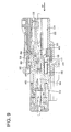
- the connector housing 300 is made e.g. of a synthetic resin and includes a housing main body 302 formed with cavities 301 capable of at least partly accommodating female terminal fittings 400 and a fitting tube portion 303 at least partly surrounding the housing main body 302, wherein a mating receptacle 501 is at least partly fittable between the housing main body 302 and the fitting tube portion 303 from front (or along connecting and separating directions CSD).
- a mount space for a connection detecting member 330 penetrates the connector housing 300 substantially in forward and backward directions FBD between the upper surface of the housing main body 302 and the lower surface of the fitting tube portion 303.
- At least one lock arm 304 is formed on the lateral (upper) surface of the housing main body 302, and the connection detecting member 330 is so mounted as to be connectable with the lock arm 304.
- the connection detecting member 330 is movable or displaceable between a standby position (first position) and a detecting position (second position) with respect to the lock arm 304, and is normally kept at the standby position with a movement to the detecting position prevented by being engaged with a restricting portion 304 formed on the lock arm 304, whereas the connection detecting member 330 is permitted to move to the detecting position by being disengaged from the restricting portion 305 only when the two connector housings 300, 500 are properly connected. Accordingly, a connected state of the two connector housings 300, 500 can be detected or verified depending on whether or not the movement of the connection detecting member 330 is possible.
- the lock arm 304 includes one or more leg portions 306 standing up from an intermediate part of the lateral (upper) surface of the housing main body 302 in forward and backward directions FBD and an arm portion 307 extending substantially in forward and backward directions FBD from the distal (upper) ends of the leg portions 306, wherein the arm portion 307 is pivotally displaceable (resiliently displaceable or displaceable like a seesaw) with the leg portions 306 as supporting points.
- An interlocking portion 308 engageable with a mating lock portion 530 is formed at the leading end of the lock arm 304 and doubles as the restricting portion 305.
- An accommodating chamber 310 for a wire pressing member 309 is so formed in or near the rear end of the lateral (upper) surface of the housing main body 302 as to communicate with the cavities 301.
- the wire pressing member 309 has one or more sawtooth-shaped projections 311, and can prevent loose movements of wires 450 in the cavities 301 by being at least partly inserted into the accommodating chamber 309 to cause the respective projections 311 to engage or bite into the insulation coatings of the wires 450.
- the wire pressing member 309 at least partly inserted into the accommodating chamber 309 is covered by the connection detecting member 330 from above, whereby the wire pressing member 309 is prevented from accidentally coming out of the accommodating chamber 309.
- a plurality of (specifically five) cavities 301 are formed substantially side by side in a row at one or more stages in the housing main body 302.
- a stepped or recessed terminal receiving portion 312 is formed at an inner wall of each cavity 301, and a (preferably metal) locking portion 460 of the female terminal fitting 400 is resiliently engageable with this terminal receiving portion 312.
- One or more shorting terminal accommodating chambers 370 are formed adjacent to (preferably substantially below) the cavities 301 in the housing main body 302.
- the shorting terminal accommodating chambers 370 preferably penetrate the housing main body 302 substantially in forward and backward directions FBD substantially in parallel with the cavities 301.
- a rear opening of each shorting terminal accommodating chamber 370 serves as an insertion opening for the shorting terminal 100, through which the shorting terminal 100 is or can be inserted and withdrawn.
- Front openings of the shorting terminal accommodating chambers 370 are located before the front surfaces of the cavities 301, and lower portions (preferably substantially lower halves) thereof are closed by a front wall 320 standing up from the bottom front end (or close thereto) of the housing main body 302.
- the front wall 320 is in the form of a substantially vertical wall capable of covering the shorting terminal accommodating chambers 370 over at least part of, preferably over the substantially entire widths and functions to prevent any further forward movements of the properly mounted shorting terminals 100 and/or to protect the shorting terminals 100.
- Above the front wall 320 is formed an insertion path 321 for the disengaging portion 580.
- a projecting piece 322 is formed in the widthwise intermediate position (preferably substantially in the widthwise center of the upper edge) of the vertical wall 320, and a window hole 323 is formed to penetrate the front wall 320 in forward and backward directions FBD (thickness direction) inwardly of the projecting piece 322.
- each shorting terminal accommodating chamber 370 is formed to communicate with front parts of the two cavities 301 adjacent to each other at a substantially corresponding widthwise side out of the five cavities 301, and the shorting terminal 100 can come into contact with (preferably substantially box-shaped) terminal main bodies 430 of the terminal fittings 400 at least partly inserted into the two cavities 301 through these communicating parts.
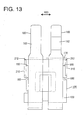
- the shorting terminal 100 is formed of an electrically conductive (preferably metal) plate material and includes a shorting terminal main body 120 (preferably substantially horizontally) arranged along (preferably the bottom surface of) the shorting terminal accommodating chamber 370 and at lest one pair of touching pieces 110 projecting from or near the front ends of the shorting terminal main body 120.
- the shorting terminal main body 120 preferably is substantially in the form of a rectangular plate as a whole, and a locking piece 140 obliquely extending downward toward the back is formed substantially in (preferably a middle part of) the shorting terminal main body 120 preferably by cutting and bending.
- the both touching pieces 110 preferably are in the form of cantilevers folded back at the front end of the shorting terminal main body 120 to extend substantially backward, and are resiliently displaceable upward and downward (otward and away from the terminal fittings 400) with the leading end of the shorting terminal main body 120 as a base end.
- One or more tapered portions 111 tapered in width direction WD are formed at intermediate positions of the touching pieces 110 in their extending direction, so that areas (preferably rear areas) of the touching pieces 110 extending substantially toward the leading ends from the tapered portions 111 preferably serve as touching portions 160 narrower than areas (front areas) thereof extending toward the base ends from the tapered portions 111.
- Each touching portion 160 is bent into a pointed or mountain-shape in side view and includes a contact portion 161 with the terminal fitting 400 at its tip or apex, and an area extending toward the base end from the contact portion 161 is formed into a slanted surface 162 sloped down toward the front from the contact portion 161.
- the slanted surfaces 162 of the touching portions 160 preferably are located above the upper end of the front wall 320 and in the insertion path 321 for the disengaging portion 580 in a mounted state of the shorting terminal 100, and the leading end of the disengaging portion 580 comes into contact with the slanted surface 162 to resiliently deform the touching portions 160 in a direction away from the (both) terminal fitting(s) 400.
- the shorting terminal 100 is formed with at least one contact piece 170 and one or more supporting pieces 210 preferably by bending.
- the contact piece 170 is bent at an angle different from 0° or 180°, preferably substantially upward substantially at right angles at (preferably the rear end edge of) the shorting terminal main body 120, and/or the substantially opposite plate surfaces thereof are oriented substantially in forward and backward directions FBD.
- the contact piece 170 preferably is in the form of a rectangular plate narrow and long in width direction WD and extending over at least part of, preferably over the substantially entire width of (preferably the rear end edge of) the shorting terminal main body 120, and the rear surface thereof serves as a pushable surface 190.
- One or more, preferably a pair of slits 180 are formed in the rear end edge of the shorting terminal main body 120 preferably at the opposite lateral (left and right) sides of the contact piece 170. By having the both slits 180, the contact piece 170 can be smoothly bent and can be arranged at an inner side of the shorting terminal main body 120.
- One or more, preferably a pair of projections 172 are formed to project substantially in width direction WD at the upper ends of the opposite lateral edges of the contact piece 170, and one or more recesses 173 are formed below the projections 172.
- the supporting pieces 210 are bent at an angle different from 0° or 180°, preferably substantially upward substantially at right angles at or near the (preferably substantially opposite) lateral edge(s) of the shorting terminal main body 120, and the (preferably substantially opposite) plate surface(s) thereof are oriented inwardly (in leftward and/or rightward directions). More specifically, the supporting pieces 210 are substantially in the form of rectangular plates located at the rear sides of the (preferably substantially opposite lateral edges of) the shorting terminal main body 120 and/or taller than the contact piece 170. The (preferably both) supporting piece(s) 210 preferably is/are located more outward in width direction than the both touching pieces 110 and do not interfere with the touching pieces 110 even if the touching pieces 110 are excessively resiliently deformed.
- One or more, preferably a pair of slits 180 are formed in (preferably each of the opposite lateral edges of) the shorting terminal main body 120 at the (preferably substantially opposite) front and/or rear sides of the supporting piece 210.
- each supporting piece 210 can be smoothly bent and can be arranged at an inner side of the shorting terminal main body 120.
- the rear ones of the pairs of slits 180 preferably communicate with the slits 180 located at the opposite sides of the contact piece 170 and are formed by largely cutting the two corners of the rear end edges of the shorting terminal main body 120.
- One or more, preferably a pair of projections 211 are formed to project backward at (preferably the bottom end of the rear end of) the supporting pieces 210, and one or more recesses 212 are formed above the projections 211.
- the projections 211 of the supporting pieces 210 are substantially aligned with and at least partly fitted into the recesses 173 of the contact piece 170 and the projections 172 of the contact piece 170 are substantially aligned with and at least partly fitted into the recesses 212 of the supporting pieces 210, and the supporting pieces 210 and the contact piece 170 preferably are inseparably interlocked with each other by the engagement of the projections 172, 211 and the recesses 173, 212 crossing substantially at right angles.
- the bottom edges of the projections 211 of the supporting pieces 210 are continuous with the upper edges of the rear slits 180.
- the mating male connector housing 500 is made e.g. of a synthetic resin material and includes a terminal accommodating portion 510 and a (preferably substantially tubular) receptacle 501 projecting from or on or at the front end of the terminal accommodating portion 510 similar to the first embodiment.
- a lock portion 530 projects from the lateral (upper) surface of the lateral (upper) wall of the receptacle 501.
- the terminal accommodating portion 510 is formed with cavities 502 arranged substantially side by side in a row in at least one stage at positions substantially corresponding to the above cavities 301, and male terminal fittings 900 are at an angle different from 0° or 180°, preferably substantially insertable into the respective cavities 502 preferably substantially from behind.
- Tab portions 902 of the terminal fittings 900 are arranged to at least partly project into the receptacle 501.
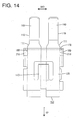
- the (preferably substantially cantilever-shaped) disengaging portions 580 located below or adjacent to the tab portions 902, extending substantially in parallel with the tab portions 902 and projecting forward are formed on the back wall of the receptacle 501.
- the front ends of the disengaging portions 580 preferably are located slightly behind the front ends of the tab portions 902, an accommodating recess 505 having a bottom surface behind the front surfaces of the cavities 502 is provided right below the disengaging portions 580, and the front wall 320 is at least partly fittable into the accommodating recess 505.
- one or more, e.g. two disengaging portions 580 are arranged substantially side by side in width direction WD in correspondence with the shorting terminals 100 and a fitting groove 506, into which the projecting piece 322 of the front wall 320 is insertable, is so formed as to communicate with the accommodating chamber 505 between the two disengaging portions 580.
- One or more disengagement guiding surfaces 581 for coming into contact with the one or more contact portions 161 of the shorting terminals 100 to resiliently deform the touching pieces 110 are provided preferably at the substantially opposite widthwise sides of the lower surfaces of the respective disengaging portions 580.
- the disengagement guiding surfaces 581 particularly are slanted surfaces sloped down toward the back, and can come into sliding contact with the slanted surfaces 162 of the contact portions 161 in the disengaging direction of the shorting terminals 100.
- Each disengaging portion 580 preferably includes a first rib 582 between the two disengagement guiding surfaces 581 and/or one or more, preferably two second ribs 583 preferably paired in width direction WD at positions at least partly vertically overlapping with the two disengagement guiding surfaces 581 in vertical direction (height direction).
- the first rib 582 preferably extends over the formation range of the two disengagement guiding surfaces 581 in forward and backward directions FBD, and/or the second ribs 583 preferably extend over their substantially entire lengths along the upper surface of a main part of the disengaging portion 580 in forward and backward directions FBD.
- the second ribs 583 preferably have substantially the same thickness as the main part of the disengaging portion 580, and the first rib 582 has such a thickness as to compensate for the main part of the disengaging portion 580 thinned by forming the disengagement guiding surfaces 581.
- the connector housing 300 and the shorting terminals 100 preferably are set in an unillustrated automatic machine and particularly substantially positioned with respect to each other and, the one or more shorting terminals 100 are at least partly accommodated into the respective shorting terminal accommodating chambers 370 through insertion openings in an inserting direction ID', preferably substantially parallel to the forward and backward directions FBD and/or from behind, by this automatic machine.
- jigs of the automatic machine are pressed against or engage the one or more pushable surfaces 190 of the contact pieces 170 to slide the shorting terminals 100 in the inserting direction ID', preferably substantially straight forward.
- a pushing force acts on the contact pieces 170 in their push-in direction ID', but the contact pieces 170 substantially are not inclined in the push-in direction of the jigs since being supported by the supporting pieces 210 preferably at or near the opposite widthwise ends of the front surfaces thereof (one or more surfaces substantially opposite to the pushable surfaces 190).
- the two touching pieces 110 are pressed from above to be resiliently deformed, but excessive deformations of the two touching pieces 110 preferably are prevented by the contact of the touching pieces 110 with the upper edge of the contact piece 170.
- the shorting terminals 100 having reached substantially proper mount positions in this way are arranged in proximity to the rear surface of the front wall 320 and prevented from coming out of the shorting terminal accommodating chambers 370 by the one or more locking pieces 140.
- the both touching pieces 110 extend obliquely backward at least partly in or into the corresponding shorting terminal accommodating chamber 370, and the contact portions 161 of the touching portions 160 are located in the front parts of the two cavities 301.
- the terminal fittings 400 are at least partly inserted into the cavities 301, they come into contact with the contact portions 161 of the shorting terminals 100 to resiliently deform the touching pieces 110 towards the shorting terminal main body 120 or substantially downward in the inserting process.
- the terminal fittings 400 located in the accommodating chambers 370 out of those 400 substantially properly inserted in the cavities 301 are in contact with the contact portions 161 of the touching portions 160 and the adjacent terminal fittings 400 are shorted with each other via the contact portions 161.
- the two connector housings 300, 500 are connected.
- the one or more disengagement guiding surfaces 581 of the disengaging portions 580 slide in surface contact with the one or more slanted surfaces 162 of the one or more touching portions 160 to guide smooth resilient deformations of the touching piece(s) 110.
- lateral shaking movements of the touching pieces 110 preferably are substantially prevented by the first ribs 582.
- the touching pieces 110 are separated from the disengagement guiding surfaces 581 to come substantially into contact with the lower surfaces (horizontal surfaces) of the base ends of the disengaging portions 580, with the result that the touching pieces 110 particularly are substantially horizontally bent and kept in their horizontal postures.
- the touching pieces 110 are pushed down to separate the contact portions 161 of the touching portions 160 from the one or more, preferably the pairs of terminal fittings 400, the shorted state of the terminal fittings 400 is canceled.
- each disengaging portion 580 preferably is formed with the first rib 582 and the second ribs 583 extending substantially in forward and backward directions FBD, the disengaging portions 580 are reinforced so that the breakage or the like of the disengaging portions 580 resulting from insufficient strength can be avoided even in such a situation where the disengaging portions 580 become relatively narrower as the connector is miniaturized.
Landscapes
- Connector Housings Or Holding Contact Members (AREA)
- Details Of Connecting Devices For Male And Female Coupling (AREA)
Applications Claiming Priority (3)
| Application Number | Priority Date | Filing Date | Title |
|---|---|---|---|
| JP2007112489 | 2007-04-23 | ||
| JP2007209454A JP4985206B2 (ja) | 2007-04-23 | 2007-08-10 | コネクタ及びショート端子 |
| EP08007320A EP1986288B1 (fr) | 2007-04-23 | 2008-04-14 | Borne de court-circuit, connecteur et son procédé d'assemblage |
Related Parent Applications (1)
| Application Number | Title | Priority Date | Filing Date |
|---|---|---|---|
| EP08007320.8 Division | 2008-04-14 |
Publications (1)
| Publication Number | Publication Date |
|---|---|
| EP2315320A1 true EP2315320A1 (fr) | 2011-04-27 |
Family
ID=39495006
Family Applications (2)
| Application Number | Title | Priority Date | Filing Date |
|---|---|---|---|
| EP08007320A Active EP1986288B1 (fr) | 2007-04-23 | 2008-04-14 | Borne de court-circuit, connecteur et son procédé d'assemblage |
| EP11001223A Withdrawn EP2315320A1 (fr) | 2007-04-23 | 2008-04-14 | Connecteur et son procédé d'assemblage |
Family Applications Before (1)
| Application Number | Title | Priority Date | Filing Date |
|---|---|---|---|
| EP08007320A Active EP1986288B1 (fr) | 2007-04-23 | 2008-04-14 | Borne de court-circuit, connecteur et son procédé d'assemblage |
Country Status (2)
| Country | Link |
|---|---|
| EP (2) | EP1986288B1 (fr) |
| JP (1) | JP4985206B2 (fr) |
Families Citing this family (11)
| Publication number | Priority date | Publication date | Assignee | Title |
|---|---|---|---|---|
| FR2944388B1 (fr) * | 2009-04-10 | 2011-05-20 | Tyco Electronics France Sas | Connecteur electrique |
| FR2948255B1 (fr) * | 2009-07-17 | 2013-07-05 | Peugeot Citroen Automobiles Sa | Dispositif de protection electrique d'un equipement comprenant au moins un element electrique sensible aux decharges electrostatiques |
| JP5594008B2 (ja) * | 2010-09-15 | 2014-09-24 | 住友電装株式会社 | コネクタ |
| JP2016058174A (ja) * | 2014-09-08 | 2016-04-21 | 住友電装株式会社 | 端子金具およびコネクタ |
| JP6023255B1 (ja) | 2015-04-17 | 2016-11-09 | イリソ電子工業株式会社 | コネクタ |
| JP6540499B2 (ja) | 2015-12-22 | 2019-07-10 | 住友電装株式会社 | コネクタ |
| JP6427146B2 (ja) * | 2016-07-29 | 2018-11-21 | 矢崎総業株式会社 | コネクタ |
| JP6427145B2 (ja) * | 2016-07-29 | 2018-11-21 | 矢崎総業株式会社 | コネクタ |
| JP6499131B2 (ja) * | 2016-07-29 | 2019-04-10 | 矢崎総業株式会社 | コネクタ |
| CN110391533A (zh) * | 2018-04-17 | 2019-10-29 | 艾默林汽车活动组件(无锡)有限公司 | 连接器及应用该连接器的车灯调节装置 |
| EP3734772B1 (fr) * | 2019-04-30 | 2022-08-10 | Aptiv Technologies Limited | Terminal de contact électrique pour connecteur de prise électrique d'un système de retenue de sécurité |
Citations (6)
| Publication number | Priority date | Publication date | Assignee | Title |
|---|---|---|---|---|
| DE4342820A1 (de) * | 1992-12-21 | 1994-06-23 | Whitaker Corp | Zweiteiliger elektrischer Verbinder mit Kurzschließmöglichkeit und Kurzschließfeder für diesen |
| JPH09153386A (ja) | 1995-09-25 | 1997-06-10 | Yazaki Corp | コネクタの結合検知装置 |
| EP0808000A2 (fr) * | 1996-05-17 | 1997-11-19 | Yazaki Corporation | Structure de connecteur |
| EP0822620A1 (fr) * | 1996-07-25 | 1998-02-04 | Sumitomo Wiring Systems, Ltd. | Contact pour shunt et connecteur électrique correspondant |
| EP1521335A2 (fr) * | 2003-10-01 | 2005-04-06 | Sumitomo Wiring Systems, Ltd. | Dispositif de connection |
| US20070054547A1 (en) * | 2005-09-05 | 2007-03-08 | Yazaki Corporation | Electric connector |
Family Cites Families (5)
| Publication number | Priority date | Publication date | Assignee | Title |
|---|---|---|---|---|
| DE4342830C1 (de) | 1993-12-15 | 1995-04-20 | Haeusler Gerd | Vorrichtung zur Erzeugung streifenartiger Lichtmuster |
| JP3253805B2 (ja) * | 1994-07-08 | 2002-02-04 | タイコエレクトロニクスアンプ株式会社 | 短絡型電気コネクタ |
| JP3619300B2 (ja) * | 1995-10-11 | 2005-02-09 | 矢崎総業株式会社 | コネクタの結合検知装置 |
| JP3674280B2 (ja) * | 1997-04-03 | 2005-07-20 | 住友電装株式会社 | コネクタ |
| TW542455U (en) * | 2001-12-26 | 2003-07-11 | Hon Hai Prec Ind Co Ltd | Power connector |
-
2007
- 2007-08-10 JP JP2007209454A patent/JP4985206B2/ja not_active Expired - Fee Related
-
2008
- 2008-04-14 EP EP08007320A patent/EP1986288B1/fr active Active
- 2008-04-14 EP EP11001223A patent/EP2315320A1/fr not_active Withdrawn
Patent Citations (6)
| Publication number | Priority date | Publication date | Assignee | Title |
|---|---|---|---|---|
| DE4342820A1 (de) * | 1992-12-21 | 1994-06-23 | Whitaker Corp | Zweiteiliger elektrischer Verbinder mit Kurzschließmöglichkeit und Kurzschließfeder für diesen |
| JPH09153386A (ja) | 1995-09-25 | 1997-06-10 | Yazaki Corp | コネクタの結合検知装置 |
| EP0808000A2 (fr) * | 1996-05-17 | 1997-11-19 | Yazaki Corporation | Structure de connecteur |
| EP0822620A1 (fr) * | 1996-07-25 | 1998-02-04 | Sumitomo Wiring Systems, Ltd. | Contact pour shunt et connecteur électrique correspondant |
| EP1521335A2 (fr) * | 2003-10-01 | 2005-04-06 | Sumitomo Wiring Systems, Ltd. | Dispositif de connection |
| US20070054547A1 (en) * | 2005-09-05 | 2007-03-08 | Yazaki Corporation | Electric connector |
Also Published As
| Publication number | Publication date |
|---|---|
| EP1986288B1 (fr) | 2011-10-19 |
| JP2008293938A (ja) | 2008-12-04 |
| JP4985206B2 (ja) | 2012-07-25 |
| EP1986288A1 (fr) | 2008-10-29 |
Similar Documents
| Publication | Publication Date | Title |
|---|---|---|
| US7901229B2 (en) | Shorting terminal, a connector and an assembling method therefor | |
| EP1986288B1 (fr) | Borne de court-circuit, connecteur et son procédé d'assemblage | |
| US7396253B2 (en) | Connector and a connector assembly | |
| EP2416454B1 (fr) | Connecteur | |
| EP1936749B1 (fr) | Organe de contact, connecteur et procédé de fabrication | |
| US7223113B2 (en) | Connector and a connector assembly | |
| US7575464B2 (en) | Connector with channel-shaped clearance between lock arm and projection to prevent entry of wires | |
| US6942510B2 (en) | Connector and a connector system | |
| EP2437357A1 (fr) | Connecteur | |
| EP1689041A1 (fr) | Connecteur , dispositif de test pour des connecteurs et procédé | |
| EP1863134A2 (fr) | Connecteur et gabarit de déblocage de celui-ci | |
| US8449319B2 (en) | Connector | |
| US6702614B2 (en) | Connector with lock configured to avoid interference with terminal fitting | |
| EP1801925A1 (fr) | Connecteur et ensemble de connecteurs | |
| US7008254B2 (en) | Connector | |
| US6976874B2 (en) | Terminal fitting and connector provided therewith | |
| US6851987B2 (en) | Connector | |
| EP1801926B1 (fr) | Connecteur et ensemble de connecteurs | |
| US7001206B2 (en) | Connector and a connector assembly | |
| US8337255B2 (en) | Connector and series of connectors | |
| EP1796226A2 (fr) | Elektrischer Verbinder und Verbinderanordnung | |
| JP7368165B2 (ja) | コネクタ | |
| US20040192118A1 (en) | Connector | |
| US20220059963A1 (en) | Connector |
Legal Events
| Date | Code | Title | Description |
|---|---|---|---|
| PUAI | Public reference made under article 153(3) epc to a published international application that has entered the european phase |
Free format text: ORIGINAL CODE: 0009012 |
|
| AC | Divisional application: reference to earlier application |
Ref document number: 1986288 Country of ref document: EP Kind code of ref document: P |
|
| AK | Designated contracting states |
Kind code of ref document: A1 Designated state(s): DE FR |
|
| STAA | Information on the status of an ep patent application or granted ep patent |
Free format text: STATUS: THE APPLICATION IS DEEMED TO BE WITHDRAWN |
|
| 18D | Application deemed to be withdrawn |
Effective date: 20111028 |