EP1522780A1 - Kunststoffschlauch - Google Patents
Kunststoffschlauch Download PDFInfo
- Publication number
- EP1522780A1 EP1522780A1 EP04020862A EP04020862A EP1522780A1 EP 1522780 A1 EP1522780 A1 EP 1522780A1 EP 04020862 A EP04020862 A EP 04020862A EP 04020862 A EP04020862 A EP 04020862A EP 1522780 A1 EP1522780 A1 EP 1522780A1
- Authority
- EP
- European Patent Office
- Prior art keywords
- layer
- resin
- resin tube
- tube according
- layers
- Prior art date
- Legal status (The legal status is an assumption and is not a legal conclusion. Google has not performed a legal analysis and makes no representation as to the accuracy of the status listed.)
- Withdrawn
Links
- 229920005989 resin Polymers 0.000 title claims abstract description 136
- 239000011347 resin Substances 0.000 title claims abstract description 136
- LYCAIKOWRPUZTN-UHFFFAOYSA-N Ethylene glycol Chemical compound OCCO LYCAIKOWRPUZTN-UHFFFAOYSA-N 0.000 claims abstract description 22
- -1 polybutylene naphthalate Polymers 0.000 claims abstract description 20
- 229920001577 copolymer Polymers 0.000 claims abstract description 16
- WGCNASOHLSPBMP-UHFFFAOYSA-N hydroxyacetaldehyde Natural products OCC=O WGCNASOHLSPBMP-UHFFFAOYSA-N 0.000 claims abstract description 11
- KKEYFWRCBNTPAC-UHFFFAOYSA-L terephthalate(2-) Chemical compound [O-]C(=O)C1=CC=C(C([O-])=O)C=C1 KKEYFWRCBNTPAC-UHFFFAOYSA-L 0.000 claims abstract description 3
- 239000010410 layer Substances 0.000 claims description 230
- 239000000446 fuel Substances 0.000 claims description 53
- 229920001707 polybutylene terephthalate Polymers 0.000 claims description 41
- 239000011241 protective layer Substances 0.000 claims description 20
- 239000002253 acid Substances 0.000 claims description 15
- WERYXYBDKMZEQL-UHFFFAOYSA-N butane-1,4-diol Chemical compound OCCCCO WERYXYBDKMZEQL-UHFFFAOYSA-N 0.000 claims description 14
- KKEYFWRCBNTPAC-UHFFFAOYSA-N Terephthalic acid Chemical compound OC(=O)C1=CC=C(C(O)=O)C=C1 KKEYFWRCBNTPAC-UHFFFAOYSA-N 0.000 claims description 12
- 239000000539 dimer Substances 0.000 claims description 6
- 229920000728 polyester Polymers 0.000 claims description 5
- 229920001971 elastomer Polymers 0.000 description 34
- 239000000806 elastomer Substances 0.000 description 32
- 239000000463 material Substances 0.000 description 18
- LFQSCWFLJHTTHZ-UHFFFAOYSA-N Ethanol Chemical compound CCO LFQSCWFLJHTTHZ-UHFFFAOYSA-N 0.000 description 13
- 230000000052 comparative effect Effects 0.000 description 9
- 239000012790 adhesive layer Substances 0.000 description 8
- BJZYYSAMLOBSDY-QMMMGPOBSA-N (2s)-2-butoxybutan-1-ol Chemical compound CCCCO[C@@H](CC)CO BJZYYSAMLOBSDY-QMMMGPOBSA-N 0.000 description 7
- 238000004519 manufacturing process Methods 0.000 description 7
- OKKJLVBELUTLKV-UHFFFAOYSA-N Methanol Chemical compound OC OKKJLVBELUTLKV-UHFFFAOYSA-N 0.000 description 6
- 238000012360 testing method Methods 0.000 description 6
- 230000004888 barrier function Effects 0.000 description 5
- 229920005604 random copolymer Polymers 0.000 description 5
- 229920000299 Nylon 12 Polymers 0.000 description 4
- 238000005452 bending Methods 0.000 description 4
- 125000001153 fluoro group Chemical group F* 0.000 description 4
- 239000002184 metal Substances 0.000 description 4
- 229910052751 metal Inorganic materials 0.000 description 4
- 239000000126 substance Substances 0.000 description 4
- 239000004734 Polyphenylene sulfide Substances 0.000 description 3
- 229920001400 block copolymer Polymers 0.000 description 3
- 239000000945 filler Substances 0.000 description 3
- 239000000203 mixture Substances 0.000 description 3
- 229920001225 polyester resin Polymers 0.000 description 3
- 239000004645 polyester resin Substances 0.000 description 3
- 229920000069 polyphenylene sulfide Polymers 0.000 description 3
- 150000003504 terephthalic acids Chemical class 0.000 description 3
- VGGSQFUCUMXWEO-UHFFFAOYSA-N Ethene Chemical compound C=C VGGSQFUCUMXWEO-UHFFFAOYSA-N 0.000 description 2
- 239000005977 Ethylene Substances 0.000 description 2
- QIGBRXMKCJKVMJ-UHFFFAOYSA-N Hydroquinone Chemical compound OC1=CC=C(O)C=C1 QIGBRXMKCJKVMJ-UHFFFAOYSA-N 0.000 description 2
- 239000012298 atmosphere Substances 0.000 description 2
- 239000002131 composite material Substances 0.000 description 2
- 238000011156 evaluation Methods 0.000 description 2
- 230000008020 evaporation Effects 0.000 description 2
- 238000001704 evaporation Methods 0.000 description 2
- 238000001125 extrusion Methods 0.000 description 2
- 239000012530 fluid Substances 0.000 description 2
- 239000003273 ketjen black Substances 0.000 description 2
- 230000004048 modification Effects 0.000 description 2
- 238000012986 modification Methods 0.000 description 2
- UTOPWMOLSKOLTQ-UHFFFAOYSA-N octacosanoic acid Chemical compound CCCCCCCCCCCCCCCCCCCCCCCCCCCC(O)=O UTOPWMOLSKOLTQ-UHFFFAOYSA-N 0.000 description 2
- GLDOVTGHNKAZLK-UHFFFAOYSA-N octadecan-1-ol Chemical compound CCCCCCCCCCCCCCCCCCO GLDOVTGHNKAZLK-UHFFFAOYSA-N 0.000 description 2
- 229920006122 polyamide resin Polymers 0.000 description 2
- 238000004064 recycling Methods 0.000 description 2
- GHMLBKRAJCXXBS-UHFFFAOYSA-N resorcinol Chemical compound OC1=CC=CC(O)=C1 GHMLBKRAJCXXBS-UHFFFAOYSA-N 0.000 description 2
- 239000005060 rubber Substances 0.000 description 2
- 150000003839 salts Chemical class 0.000 description 2
- CYTCTRAEJYIZRX-UHFFFAOYSA-N (9a-hydroxy-3,5a-dimethyl-9-methylidene-2-oxo-3,3a,4,5,6,7,8,9b-octahydrobenzo[g][1]benzofuran-6-yl) acetate Chemical compound C1CC2(C)C(OC(C)=O)CCC(=C)C2(O)C2C1C(C)C(=O)O2 CYTCTRAEJYIZRX-UHFFFAOYSA-N 0.000 description 1
- WUPHOULIZUERAE-UHFFFAOYSA-N 3-(oxolan-2-yl)propanoic acid Chemical compound OC(=O)CCC1CCCO1 WUPHOULIZUERAE-UHFFFAOYSA-N 0.000 description 1
- 239000005995 Aluminium silicate Substances 0.000 description 1
- 229920000571 Nylon 11 Polymers 0.000 description 1
- 229920002292 Nylon 6 Polymers 0.000 description 1
- 229920002302 Nylon 6,6 Polymers 0.000 description 1
- ISWSIDIOOBJBQZ-UHFFFAOYSA-N Phenol Chemical compound OC1=CC=CC=C1 ISWSIDIOOBJBQZ-UHFFFAOYSA-N 0.000 description 1
- 239000004698 Polyethylene Substances 0.000 description 1
- 239000004743 Polypropylene Substances 0.000 description 1
- OFOBLEOULBTSOW-UHFFFAOYSA-N Propanedioic acid Natural products OC(=O)CC(O)=O OFOBLEOULBTSOW-UHFFFAOYSA-N 0.000 description 1
- 241000872198 Serjania polyphylla Species 0.000 description 1
- BQCADISMDOOEFD-UHFFFAOYSA-N Silver Chemical compound [Ag] BQCADISMDOOEFD-UHFFFAOYSA-N 0.000 description 1
- 235000021355 Stearic acid Nutrition 0.000 description 1
- 239000006096 absorbing agent Substances 0.000 description 1
- 230000003213 activating effect Effects 0.000 description 1
- 235000012211 aluminium silicate Nutrition 0.000 description 1
- 239000003963 antioxidant agent Substances 0.000 description 1
- 230000003078 antioxidant effect Effects 0.000 description 1
- KDFQYGBJUYYWDJ-UHFFFAOYSA-N azane;sodium Chemical compound N.[Na] KDFQYGBJUYYWDJ-UHFFFAOYSA-N 0.000 description 1
- 230000008901 benefit Effects 0.000 description 1
- RWCCWEUUXYIKHB-UHFFFAOYSA-N benzophenone Chemical compound C=1C=CC=CC=1C(=O)C1=CC=CC=C1 RWCCWEUUXYIKHB-UHFFFAOYSA-N 0.000 description 1
- 239000012965 benzophenone Substances 0.000 description 1
- QRUDEWIWKLJBPS-UHFFFAOYSA-N benzotriazole Chemical compound C1=CC=C2N[N][N]C2=C1 QRUDEWIWKLJBPS-UHFFFAOYSA-N 0.000 description 1
- 239000012964 benzotriazole Substances 0.000 description 1
- 229920000402 bisphenol A polycarbonate polymer Polymers 0.000 description 1
- 229910052980 cadmium sulfide Inorganic materials 0.000 description 1
- 239000003795 chemical substances by application Substances 0.000 description 1
- 239000012459 cleaning agent Substances 0.000 description 1
- 239000003086 colorant Substances 0.000 description 1
- 239000000470 constituent Substances 0.000 description 1
- 230000008878 coupling Effects 0.000 description 1
- 238000010168 coupling process Methods 0.000 description 1
- 238000005859 coupling reaction Methods 0.000 description 1
- 239000003484 crystal nucleating agent Substances 0.000 description 1
- 125000003700 epoxy group Chemical group 0.000 description 1
- 230000001747 exhibiting effect Effects 0.000 description 1
- 230000002349 favourable effect Effects 0.000 description 1
- 239000012760 heat stabilizer Substances 0.000 description 1
- 230000007062 hydrolysis Effects 0.000 description 1
- 238000006460 hydrolysis reaction Methods 0.000 description 1
- 229910010272 inorganic material Inorganic materials 0.000 description 1
- 239000011147 inorganic material Substances 0.000 description 1
- JEIPFZHSYJVQDO-UHFFFAOYSA-N iron(III) oxide Inorganic materials O=[Fe]O[Fe]=O JEIPFZHSYJVQDO-UHFFFAOYSA-N 0.000 description 1
- NLYAJNPCOHFWQQ-UHFFFAOYSA-N kaolin Chemical compound O.O.O=[Al]O[Si](=O)O[Si](=O)O[Al]=O NLYAJNPCOHFWQQ-UHFFFAOYSA-N 0.000 description 1
- 238000004898 kneading Methods 0.000 description 1
- 239000000314 lubricant Substances 0.000 description 1
- VZCYOOQTPOCHFL-UPHRSURJSA-N maleic acid Chemical compound OC(=O)\C=C/C(O)=O VZCYOOQTPOCHFL-UPHRSURJSA-N 0.000 description 1
- 239000011976 maleic acid Substances 0.000 description 1
- 238000005259 measurement Methods 0.000 description 1
- 230000008018 melting Effects 0.000 description 1
- 238000002844 melting Methods 0.000 description 1
- 150000002739 metals Chemical class 0.000 description 1
- 238000000034 method Methods 0.000 description 1
- GOQYKNQRPGWPLP-UHFFFAOYSA-N n-heptadecyl alcohol Natural products CCCCCCCCCCCCCCCCCO GOQYKNQRPGWPLP-UHFFFAOYSA-N 0.000 description 1
- LYRFLYHAGKPMFH-UHFFFAOYSA-N octadecanamide Chemical compound CCCCCCCCCCCCCCCCCC(N)=O LYRFLYHAGKPMFH-UHFFFAOYSA-N 0.000 description 1
- QIQXTHQIDYTFRH-UHFFFAOYSA-N octadecanoic acid Chemical compound CCCCCCCCCCCCCCCCCC(O)=O QIQXTHQIDYTFRH-UHFFFAOYSA-N 0.000 description 1
- OQCDKBAXFALNLD-UHFFFAOYSA-N octadecanoic acid Natural products CCCCCCCC(C)CCCCCCCCC(O)=O OQCDKBAXFALNLD-UHFFFAOYSA-N 0.000 description 1
- AQSJGOWTSHOLKH-UHFFFAOYSA-N phosphite(3-) Chemical class [O-]P([O-])[O-] AQSJGOWTSHOLKH-UHFFFAOYSA-N 0.000 description 1
- IEQIEDJGQAUEQZ-UHFFFAOYSA-N phthalocyanine Chemical compound N1C(N=C2C3=CC=CC=C3C(N=C3C4=CC=CC=C4C(=N4)N3)=N2)=C(C=CC=C2)C2=C1N=C1C2=CC=CC=C2C4=N1 IEQIEDJGQAUEQZ-UHFFFAOYSA-N 0.000 description 1
- 239000000049 pigment Substances 0.000 description 1
- 229920005668 polycarbonate resin Polymers 0.000 description 1
- 239000004431 polycarbonate resin Substances 0.000 description 1
- 229920000573 polyethylene Polymers 0.000 description 1
- 229920001155 polypropylene Polymers 0.000 description 1
- 230000002787 reinforcement Effects 0.000 description 1
- YGSDEFSMJLZEOE-UHFFFAOYSA-M salicylate Chemical compound OC1=CC=CC=C1C([O-])=O YGSDEFSMJLZEOE-UHFFFAOYSA-M 0.000 description 1
- 229960001860 salicylate Drugs 0.000 description 1
- 238000007789 sealing Methods 0.000 description 1
- 229920002545 silicone oil Polymers 0.000 description 1
- 229920002050 silicone resin Polymers 0.000 description 1
- 229910052709 silver Inorganic materials 0.000 description 1
- 239000004332 silver Substances 0.000 description 1
- 239000002356 single layer Substances 0.000 description 1
- 239000008117 stearic acid Substances 0.000 description 1
- 125000001424 substituent group Chemical group 0.000 description 1
- 238000004381 surface treatment Methods 0.000 description 1
- 239000000454 talc Substances 0.000 description 1
- 229910052623 talc Inorganic materials 0.000 description 1
- 150000003568 thioethers Chemical class 0.000 description 1
- VZCYOOQTPOCHFL-UHFFFAOYSA-N trans-butenedioic acid Natural products OC(=O)C=CC(O)=O VZCYOOQTPOCHFL-UHFFFAOYSA-N 0.000 description 1
- XLYOFNOQVPJJNP-UHFFFAOYSA-N water Substances O XLYOFNOQVPJJNP-UHFFFAOYSA-N 0.000 description 1
Images
Classifications
-
- B—PERFORMING OPERATIONS; TRANSPORTING
- B32—LAYERED PRODUCTS
- B32B—LAYERED PRODUCTS, i.e. PRODUCTS BUILT-UP OF STRATA OF FLAT OR NON-FLAT, e.g. CELLULAR OR HONEYCOMB, FORM
- B32B1/00—Layered products having a non-planar shape
- B32B1/08—Tubular products
-
- B—PERFORMING OPERATIONS; TRANSPORTING
- B32—LAYERED PRODUCTS
- B32B—LAYERED PRODUCTS, i.e. PRODUCTS BUILT-UP OF STRATA OF FLAT OR NON-FLAT, e.g. CELLULAR OR HONEYCOMB, FORM
- B32B27/00—Layered products comprising a layer of synthetic resin
- B32B27/36—Layered products comprising a layer of synthetic resin comprising polyesters
-
- F—MECHANICAL ENGINEERING; LIGHTING; HEATING; WEAPONS; BLASTING
- F16—ENGINEERING ELEMENTS AND UNITS; GENERAL MEASURES FOR PRODUCING AND MAINTAINING EFFECTIVE FUNCTIONING OF MACHINES OR INSTALLATIONS; THERMAL INSULATION IN GENERAL
- F16L—PIPES; JOINTS OR FITTINGS FOR PIPES; SUPPORTS FOR PIPES, CABLES OR PROTECTIVE TUBING; MEANS FOR THERMAL INSULATION IN GENERAL
- F16L11/00—Hoses, i.e. flexible pipes
- F16L11/04—Hoses, i.e. flexible pipes made of rubber or flexible plastics
- F16L11/045—Hoses, i.e. flexible pipes made of rubber or flexible plastics with four or more layers without reinforcement
-
- F—MECHANICAL ENGINEERING; LIGHTING; HEATING; WEAPONS; BLASTING
- F16—ENGINEERING ELEMENTS AND UNITS; GENERAL MEASURES FOR PRODUCING AND MAINTAINING EFFECTIVE FUNCTIONING OF MACHINES OR INSTALLATIONS; THERMAL INSULATION IN GENERAL
- F16L—PIPES; JOINTS OR FITTINGS FOR PIPES; SUPPORTS FOR PIPES, CABLES OR PROTECTIVE TUBING; MEANS FOR THERMAL INSULATION IN GENERAL
- F16L11/00—Hoses, i.e. flexible pipes
- F16L11/04—Hoses, i.e. flexible pipes made of rubber or flexible plastics
- F16L11/11—Hoses, i.e. flexible pipes made of rubber or flexible plastics with corrugated wall
-
- F—MECHANICAL ENGINEERING; LIGHTING; HEATING; WEAPONS; BLASTING
- F16—ENGINEERING ELEMENTS AND UNITS; GENERAL MEASURES FOR PRODUCING AND MAINTAINING EFFECTIVE FUNCTIONING OF MACHINES OR INSTALLATIONS; THERMAL INSULATION IN GENERAL
- F16L—PIPES; JOINTS OR FITTINGS FOR PIPES; SUPPORTS FOR PIPES, CABLES OR PROTECTIVE TUBING; MEANS FOR THERMAL INSULATION IN GENERAL
- F16L11/00—Hoses, i.e. flexible pipes
- F16L11/04—Hoses, i.e. flexible pipes made of rubber or flexible plastics
- F16L11/11—Hoses, i.e. flexible pipes made of rubber or flexible plastics with corrugated wall
- F16L11/118—Hoses, i.e. flexible pipes made of rubber or flexible plastics with corrugated wall having arrangements for particular purposes, e.g. electrically conducting
- F16L11/1185—Hoses, i.e. flexible pipes made of rubber or flexible plastics with corrugated wall having arrangements for particular purposes, e.g. electrically conducting electrically conducting
-
- F—MECHANICAL ENGINEERING; LIGHTING; HEATING; WEAPONS; BLASTING
- F16—ENGINEERING ELEMENTS AND UNITS; GENERAL MEASURES FOR PRODUCING AND MAINTAINING EFFECTIVE FUNCTIONING OF MACHINES OR INSTALLATIONS; THERMAL INSULATION IN GENERAL
- F16L—PIPES; JOINTS OR FITTINGS FOR PIPES; SUPPORTS FOR PIPES, CABLES OR PROTECTIVE TUBING; MEANS FOR THERMAL INSULATION IN GENERAL
- F16L11/00—Hoses, i.e. flexible pipes
- F16L11/04—Hoses, i.e. flexible pipes made of rubber or flexible plastics
- F16L11/12—Hoses, i.e. flexible pipes made of rubber or flexible plastics with arrangements for particular purposes, e.g. specially profiled, with protecting layer, heated, electrically conducting
- F16L11/127—Hoses, i.e. flexible pipes made of rubber or flexible plastics with arrangements for particular purposes, e.g. specially profiled, with protecting layer, heated, electrically conducting electrically conducting
-
- B—PERFORMING OPERATIONS; TRANSPORTING
- B32—LAYERED PRODUCTS
- B32B—LAYERED PRODUCTS, i.e. PRODUCTS BUILT-UP OF STRATA OF FLAT OR NON-FLAT, e.g. CELLULAR OR HONEYCOMB, FORM
- B32B2250/00—Layers arrangement
- B32B2250/24—All layers being polymeric
-
- B—PERFORMING OPERATIONS; TRANSPORTING
- B32—LAYERED PRODUCTS
- B32B—LAYERED PRODUCTS, i.e. PRODUCTS BUILT-UP OF STRATA OF FLAT OR NON-FLAT, e.g. CELLULAR OR HONEYCOMB, FORM
- B32B2250/00—Layers arrangement
- B32B2250/40—Symmetrical or sandwich layers, e.g. ABA, ABCBA, ABCCBA
-
- B—PERFORMING OPERATIONS; TRANSPORTING
- B32—LAYERED PRODUCTS
- B32B—LAYERED PRODUCTS, i.e. PRODUCTS BUILT-UP OF STRATA OF FLAT OR NON-FLAT, e.g. CELLULAR OR HONEYCOMB, FORM
- B32B2262/00—Composition or structural features of fibres which form a fibrous or filamentary layer or are present as additives
- B32B2262/02—Synthetic macromolecular fibres
- B32B2262/0276—Polyester fibres
- B32B2262/0284—Polyethylene terephthalate [PET] or polybutylene terephthalate [PBT]
-
- F—MECHANICAL ENGINEERING; LIGHTING; HEATING; WEAPONS; BLASTING
- F16—ENGINEERING ELEMENTS AND UNITS; GENERAL MEASURES FOR PRODUCING AND MAINTAINING EFFECTIVE FUNCTIONING OF MACHINES OR INSTALLATIONS; THERMAL INSULATION IN GENERAL
- F16L—PIPES; JOINTS OR FITTINGS FOR PIPES; SUPPORTS FOR PIPES, CABLES OR PROTECTIVE TUBING; MEANS FOR THERMAL INSULATION IN GENERAL
- F16L11/00—Hoses, i.e. flexible pipes
- F16L11/04—Hoses, i.e. flexible pipes made of rubber or flexible plastics
- F16L2011/047—Hoses, i.e. flexible pipes made of rubber or flexible plastics with a diffusion barrier layer
-
- Y—GENERAL TAGGING OF NEW TECHNOLOGICAL DEVELOPMENTS; GENERAL TAGGING OF CROSS-SECTIONAL TECHNOLOGIES SPANNING OVER SEVERAL SECTIONS OF THE IPC; TECHNICAL SUBJECTS COVERED BY FORMER USPC CROSS-REFERENCE ART COLLECTIONS [XRACs] AND DIGESTS
- Y10—TECHNICAL SUBJECTS COVERED BY FORMER USPC
- Y10T—TECHNICAL SUBJECTS COVERED BY FORMER US CLASSIFICATION
- Y10T428/00—Stock material or miscellaneous articles
- Y10T428/13—Hollow or container type article [e.g., tube, vase, etc.]
- Y10T428/1352—Polymer or resin containing [i.e., natural or synthetic]
- Y10T428/139—Open-ended, self-supporting conduit, cylinder, or tube-type article
- Y10T428/1393—Multilayer [continuous layer]
Definitions
- the present invention relates to a resin tube and a tube for a fuel pipe system for motor vehicles.
- the resin tube is poor in resistance against the permeation of fuel as compared to the metallic tube, and there is requirement for further suppressing the permeation to comply with the regulations on fuel evaporation that will become more stringent in the future.
- a composite tube includes a fluorine-contained resin (ethylene/tetrafluoroethylene copolymer) as an inner layer (barrier layer), an adhesive layer as an intermediate layer, and a polyamide 12 as an outer layer (Published Japanese Patent Application Kokai No. H05(1993)-164273).
- a fluorine-contained resin ethylene/tetrafluoroethylene copolymer
- an adhesive layer as an intermediate layer
- polyamide 12 as an outer layer
- a resin tube of a second example employs a polyphenylene sulfide (PPS) as a barrier layer (Published Japanese Patent Application Kokai No. H11 (1999) -156970, and Published Japanese Patent Application Kokai No. H10(1998)-230556.
- PPS polyphenylene sulfide
- a third example employs a method of adhering a barrier layer (inner layer) and a protection layer (outer layer) together by surface treatment such as plasma (Published Japanese Patent Application Kokai No. H10(1998)-30764, and Published Japanese Patent Application Kokai No. 2000-55248).
- the first example is unsatisfactory in the following points.
- the fluoro resin itself is expensive.
- An expensive adhesive layer is used for adhering the fluoro resin and the polyamide 12. To decrease the wall thickness to reduce the cost is inadequate because the strength withstanding pressure is weakened.
- the fluoro resin is extruded to form the inner layer, and the surfaces thereof are treated by applying a chemically treating solution containing a sodium-ammonia complex to introduce activating groups. In this case, however, the steps of production process become very complex and the cost is further increased.
- the production process is complex and the above problems are not solved.
- the combination of the above different kinds of materials further, it is difficult to reuse the end materials discarded in the production process.
- a resin tube comprises: a first resin layer containing polybutylene naphthalate; second and third resin layers containing copolymer of polybutylene naphthalate and polytetramethylene glycol, the second resin layer being on an outer side of the first resin layer, and the third resin layer being on an inner side of the first resin layer; and a fourth resin layer containing polybutyene terephthalate.
- the resin tube according to the embodiment of the present invention has a multi-layer structure including at least first through fourth tubular resin layers.
- the first resin layer is a shut-off layer (fuel shut-off layer, or barrier layer or center layer) containing PBN.
- the first resin layer is interposed between the second resin layer on the outer side and the third resin layer on the inner side.
- the second and third resin layers are layers containing a copolymer of PBN and PTMG.
- the resin tube includes one or both of a layer containing PBT and a layer containing a copolymer containing PBT segments.
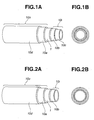
- Figs. 1A and 1B show a resin tube having a 5-layer structure according to the embodiment
- the resin tube has a hollow center portion in the central portion to permit the flow of fluid such as fuel.
- the multi layer structure of this resin tube includes a shut-off layer (first resin layer) 1, and inner and outer protection or protective layers 10i and 10o.
- Outer protective layer 10o includes an outer contact layer (second resin layer) 10a and an outermost layer (fourth or fifth resin layer) 10d.
- Inner protective layer 10i shown in Figs. 1A and 1B includes an inner contact layer (third resin layer) 10b and an innermost layer (fifth or fourth resin layer) 10c.
- Outer contact layer 10a is located directly on the outer surface of shut-off layer 1.
- Inner contact layer 10b is located directly on the inner surface of shut-off layer 1.
- Shut-off layer 1 is sandwiched between outer and inner contact layers 10a and 10b. Shut-off layer 1 is enclosed contiguously by outer contact layer 10a, and shut-off layer 1 encloses inner contact layer 10b contiguously.
- Figs. 2A and 2B show a resin tube having a 4-layer structure according to the embodiment of the present invention.
- the resin tube of Figs. 2A and 2B includes a hollow center portion in the central portion to permit the flow of fuel or the like; shut-off layer (first resin layer) 1, and inner and outer protective layers 10i and 10o.
- Outer protective layer 10o includes an outer contact layer (second resin layer) 10a and an outermost layer (fourth resin layer) 10d, as in Figs. 1A and 1B.
- Inner protective layer 10i shown in Figs. 2A and 2B includes only an inner contact layer (third resin layer) 10b, unlike the resin tube of Figs. 1A and 1B.
- outer contact layer 10a is located directly on the outer surface of shut-off layer 1.
- Inner contact layer 10b is located directly on the inner surface of shut-off layer 1.
- Shut-off layer 1 is sandwiched contiguously between outer and inner contact layers 10a and 10b.
- the (fuel) shut-off layer 1 is a layer made of PBN to provide a resin tube having excellent resistance against the permeation of fuel even in the case of a mixed fuel containing alcohol such as ethanol and methanol, as well as ordinary gasoline fuel.
- the layers in contact with this shut-off layer 1 containing PBN i.e., the outer and inner contact layers 10a and 10b are both layers made of a copolymer of PBN and PTMG (hereinafter referred to as PBN elastomer).
- PBN elastomer layers 10a and 10b can adhere strongly to the PBN shut-off layer 1.
- Each of the innermost layer 10c and outermost layer 10d is a layer of inexpensive PBT or a layer of a copolymer containing PBT segments (hereinafter referred to as PBT elastomer). As a result, it is possible to produce resin tubes economically and inexpensively.
- the PBN containing layer (1) may be a layer made of PBN
- the PBN elastomer containing layer (10a and 10b) may be a layer made of PBN elastomer
- the PBT containing layer (10c and/or 10d) may be a layer made of PBT
- the PBT elastomer containing layer (10c and/or 10d) may be a layer made of PBT elastomer.
- each of the fuel shut-off layer 1 and protective layers 10o and 10i is made of polyester resin.
- Each layer is made of material selected from the group of polyester resins consisting of PBN, PBT elastomer, PBN elastomer and PBT. Therefore, owing to a high degree of miscibility, discarded resin pieces produced in production process and old resin tubes can be pulverized and melted together without separating the constituent layers, so that the recycling is easy either within the production process or outside the production process. Moreover, the adhesion between any two adjacent layers is firm.
- innermost layer 10c in the case of Figs. 1A and 1B
- inner contact layer 10b in the case of Figs. 2A and 2B
- PBN elastomer PBT elastomer
- PBT PBT
- the fuel shut-off layer 1 and the protection layers 10o and 10i markedly improve the sealing properties with metals. Therefore, even when a coupling or other metallic part is inserted in this tube, the resin tube is resistant to slippage, unlike the tube of fluoro resin.
- the PBN is best among the above-mentioned polyester resins, followed by PBT, PBN elastomer and PBT elastomer in this order. Therefore, the innermost layer 10c is desirably the PBT-containing layer, and is next desirably the PBN elastomer-containing layer.
- the polypropylene or the polyethylene that is less compatible with innermost layer 10c or inner contact layer 10b can be mixed, like the above polyamide resins, by introducing the epoxy groups or by treatment such as modification with maleic acid. In this case, too, the cost of the material can be further reduced.
- the resin tube according to the embodiment of the present invention has the flexible layer containing PBN elastomer and further has the layer containing the PBT elastomer depending upon the constitution.
- the tube according to the embodiment can be mounted and arranged in a vehicle permitting easy bending.
- the material of the portion on the outermost side of the protection layer 10 is selected from the PBN elastomer, PBT elastomer and PBT. Even when contacted to the fuel, therefore, the resin tube exhibits a sufficient resistance against the fuel.
- the elastomers have bending moduli of elasticity smaller than or equal to 1.5 GPa at normal temperature.
- the bending modulus of elasticity is preferably smaller than or equal to 1.0 GPa at normal temperature.
- the hardness of the material can be suitably selected depending upon a desired hardness as the resin tube.
- the PBT elastomer used in the embodiment it is desirable to use a block copolymer containing PBT as a hard segment and PTMG as a soft segment, from the standpoint of availability in the market and softness at low temperatures.
- the PBT elastomer it is desirable to use a random copolymer containing either one or both of a terephthalic acid and an ester-forming derivative thereof as acid components, containing either one or both of a hydrogenated dimer acid and an ester-forming derivative thereof, and containing 1,4-butane diol as a glycol component, from the standpoint of resistance against the fuels.
- the former block copolymer features excellent flexibility at low temperatures among the above properties and can be desirably used for partly or entirely forming protection layers 10o and 10i, and the latter random copolymer exhibits excellent resistance against the fuels such as deteriorated gasoline and can be desirably used for forming innermost layer 10c.
- the copolymer containing the PBT segment may be a copolymerized polyester obtained by copolymerizing, with the PTMG, a copolymerized polyester that contains one or both of the terephthalic acid and the ester-forming derivative thereof as acid components, containing one or both of the hydrogenated dimer (dimeric) acid and the ester-forming derivative thereof, and containing 1,4-butane diol as the glycol component.
- the thus improved PBT elastomer can be used for any layer in the protection layer 10.
- the thus improved PBT elastomer exhibits resistance against the fuels inferior to that of the PBT but is comparable to or superior to that of the PBN elastomer.
- the PBT elastomer of either the block type or the random type has a melting temperature close to that of PBN in fuel shut-off layer 1. By using the same cross head, therefore, the resin tube can be obtained simultaneously by extrusion.
- the recycling is easier and, besides, there is no need of separately providing an adhesive layer unlike that of the prior art. Further, since no adhesive layer is required, it is possible to improve other properties such as resistance against the permeation of fuel, resistance against the fuel and flexibility.
- the materials constituting the fuel shut-off layer 1 and the protection layers 10o and 10i described above need not be particular materials but may be those which are easily available in the market.
- the heat resistance and hydrolysis resistance can be suitably imparted or filler may be mixed to impart electric conduction, or inorganic materials may be mixed for reinforcement.
- an electrically conducting filler such as Ketjen Black is mixed into the resin of the innermost layer 10c so that the volume resistivity thereof is in the range of 10 2 to 10 6 ⁇ cm, it is possible to prevent flow electrification or electrification induced by the flow even when the resin tube is used as a pipe for conveying the fluid at a high speed, such as a feed line of a vehicle.
- the resin tube according to the embodiment of the invention has a multi-layer structure including the PBN containing layer (first resin layer)(1), the PBN elastomer containing layers (second and third resin layers)(10a, 10b) and at least one PBT layer which may be the PBT containing layer or the PBT elastomer containing layer.
- the PBN containing layer (1) is sandwiched between the two PBN elastomer containing layers (10a and 10b).
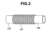
- the resin tube of the invention may further include one or more fuel shut-off layers and protection layers to meet the use and requirement, or may have a convoluted or bellows structure as will be described later in detail.
- the pleated portion extends in the longitudinal direction of the resin tube, for example, between two straight plain portions of the resin tube.
- a convoluted (or corrugated) portion 101 is formed between two straight portions 102.
- the resin tube can be used as a pipe having a diameter of not smaller than 10 mm, such as a bent hose in the fuel system of the vehicles, finding widespread applications.
- the resin tube according to the embodiment of the invention exhibits excellent resistance against the permeation of fuel, i.e., a high fuel shut-off property not only for gasoline fuels but also alcohol-containing fuels. Therefore, the resin tube is especially suitable for use as fuel pipes for vehicles.
- each layer has a thickness of not smaller than 5% relative to the thickness of the whole layer structure (the wall thickness of the resin tube).
- the percentage of thickness of the fuel shut-off layer is 5 to 20% of the thickness of the whole layer structure.
- the wall thickness measured in the radial direction is 1 mm (0.2+0.1+0.1+0.1+0.5).
- the PBN containing shut-off layer 1 is disposed at or near the middle in the total (radial) thickness of the resin tube. That is, the PBN containing layer is located at a position nearly one-half the wall thickness of the resin tube. In the case in which the (radial) wall thickness of the tube is 1 mm, the PBN containing layer is so arranged as to occupy a position of 0.5 mm.
- the arrangement in which the PBN layer is located at the middle is particularly preferable. That is, preferably, the outer protective layer 10o and the inner protective layer 10i are substantially equal in thickness measured in the radial direction of the tube.
- a hollow tube having a wall thickness of 1 mm has a five-layer structure as shown in Figs. 1A and 1B composed of a 0.3 mm thick innermost layer 10c, a 0. 15 mm thick inner contact layer 10b, 0.1 mm thick shut-off layer 1, a 0.1 mm thick outer contact layer 10a, and a 0.35 mm thick outermost layer 10d.
- This example can further provide excellent impact resistance at low temperatures.
- the outer diameter of the resin tube is typically in the range of 3 ⁇ 40 mm, and the wall thickness is generally about 0.5 ⁇ 3 mm.
- the wall thickness may be suitably varied according to the need.
- a resin tube (extruded outside diameter of 8 mm, inside diameter of 6 mm) having a five-layer structure shown in Figs. 1A and 1B was obtained by extruding PBT (700FP manufactured by Polyplastics Co.) as the innermost layer; and PBN elastomer (L4310AN manufactured by Teijin Chemicals Ltd.), PBN (TQB-OT manufactured by Teij in Chemicals Ltd.) and PBN elastomer (L4310AN manufactured by Teijin Chemicals Ltd.) as intermediate layers in this order from the inner side; and PBT elastomer (Hytrel 5577 manufactured by Du Pont-Toray Co., Ltd.) as the outermost layer, at a layer thickness ratio of 0.2:0.1:0.1:0.1:0.5 from the innermost side.
- a resin tube having the same five-layer structure was obtained in the same manner as in Example 1 but by using the PBT elastomer (Hytrel 7277 manufactured by Du Pont-Toray Co., Ltd.) which is a block copolymer of PBT and PTMG, as the innermost layer.
- PBT elastomer Hytrel 7277 manufactured by Du Pont-Toray Co., Ltd.
- a resin tube having the same five-layer structure was obtained in the same manner as in Example 1 but by using a random copolymer (PBTS 01562 manufactured by Kanebo Gohsen, Ltd.) of terephthalic acid/hydrogenated dimer (or dimeric) acid/1,4-butane diol, as the innermost layer.
- PBTS 01562 manufactured by Kanebo Gohsen, Ltd.
- a resin tube having the same five-layer structure was obtained in the same manner as in Example 1 but by using a copolymer (PBTS 01564 manufactured by Kanebo Gohsen, Ltd.) of a random copolymer of terephthalic acid/hydrogenated dimer acid/1,4-butane diol and PTMG, as the innermost layer.
- PBTS 01564 manufactured by Kanebo Gohsen, Ltd.
- a resin tube having the same five-layer structure was obtained in the same manner as in Example 1 but by using a resin (PBTS 01563 manufactured by Kanebo Gohsen, Ltd.) obtained by kneading 6% of Ketjen Black with a copolymer of PTMG and a random copolymer of terephthalic acid/hydrogenated dimer acid/1,4-butane diol, as the innermost layer.
- PBTS 01563 manufactured by Kanebo Gohsen, Ltd.
- a resin tube having the same five-layer structure was obtained in the same manner as in Practical Example 2 but by selecting the layer thickness ratio to be 0.35:0.1:0.1:0.1:0.35 from the innermost side.
- a resin tube having the same five-layer structure was obtained in the same manner as in Practical Example 2 and having a convoluted (or corrugated) portion (straight portion having an outside diameter of 16 mm and an inside diameter of 13 mm, and convoulted portion having an outer diameter of 22 mm).
- ETFE ethylene/tetrafluoroethylene copolymer
- PA12 polyamide 12
- a resin tube (extruded outside diameter of 8 mm, inside diameter of 6 mm) having a mono-layer structure was obtained by using a polyamide 11 (PA 11) only.
- Table 1 shows the specifications of the resin tubes of above Practical Example 1 (P.E. 1) to Practical Example 7 (P.E. 7) and Comparative Examples 1 and 2 (C.E. 1 and C.E. 2).
- the intermediate layer 1 stands for inner contact layer 10b
- the intermediate layer 2 stands for fuel shut-off layer 1
- the intermediate layer 3 stands for outer contact layer 10a.
- Test pieces each having a width of an inch were picked up from the resin tubes of above Examples, and were put to a 180° peeling test stipulated under JIS-K6256. As for Comparative Example 1, measurement was carried out at the interface between the inner layer and the intermediate layer.
- the materials having the same constitutions as those of the above resin tubes were extruded flat, and the obtained flat plates (having the same layer thickness ratios as the tubes and the total layer thickness of 1 mm) were tested for their resistance against the permeation of fuel.
- the samples punched into circular discs of a diameter of 70 mm were measured concerning the amount of fuel that has permeated after the passage of a prescribed period of time (800 hours) in a 60°C atmosphere of gasoline or an alcohol-containing fuel.
- the gasoline was a regular gasoline (brand name: Silver N produced by Nippon Oil Corporation (Shin-Nihon Sekiyu Co.)) available in the market, and the alcohol-containing fuel was a mixture of 90 parts by volume of the regular gasoline and 10 parts by volume of ethanol.
- a pushing rod having a mass of 0.45 kg and an end radius R of 16 mm was permitted to fall on the resin tube from a height of 305 mm in a -40°C atmosphere to measure the cold temperature impact resistance in compliance with the testing method described in JASO M317-1986 Section 8.9.
- the resin materials used in the layers according to the invention may be blended with any one or more of the following substances: an antioxidant and a heat stabilizer (e.g., hindered phenol, hydroquinone, thioether or phosphites and substituents thereof, or any combination thereof); ultraviolet-ray absorber (e.g., resorcinol, salicylate, benzotriazole and benzophenone); lubricant and parting agent (e.g., silicone resin, montanic acid and a salt thereof, stearic acid and a salt thereof, stearyl alcohol and stearylamide), coloring agent containing dye (e.g., nitrosine) and/or pigment (e.g., cadmium sulfide, phthalocyanine), additive-imparting solution (e.g., silicone oil), crystal nucleating agent (e.g., talc, kaolin), which may be added in one kind or in a suitable combination.
- an antioxidant and a heat stabilizer
- the resin tube may typically have a circular shape or an elliptic shape in cross section, or may have any other shape in cross section.
Landscapes
- Engineering & Computer Science (AREA)
- General Engineering & Computer Science (AREA)
- Mechanical Engineering (AREA)
- Rigid Pipes And Flexible Pipes (AREA)
- Laminated Bodies (AREA)
Applications Claiming Priority (2)
| Application Number | Priority Date | Filing Date | Title |
|---|---|---|---|
| JP2003315332 | 2003-09-08 | ||
| JP2003315332A JP2005081663A (ja) | 2003-09-08 | 2003-09-08 | 樹脂製チューブ及び燃料系配管用チューブ |
Publications (1)
| Publication Number | Publication Date |
|---|---|
| EP1522780A1 true EP1522780A1 (de) | 2005-04-13 |
Family
ID=34225201
Family Applications (1)
| Application Number | Title | Priority Date | Filing Date |
|---|---|---|---|
| EP04020862A Withdrawn EP1522780A1 (de) | 2003-09-08 | 2004-09-02 | Kunststoffschlauch |
Country Status (3)
| Country | Link |
|---|---|
| US (1) | US20050053742A1 (de) |
| EP (1) | EP1522780A1 (de) |
| JP (1) | JP2005081663A (de) |
Cited By (1)
| Publication number | Priority date | Publication date | Assignee | Title |
|---|---|---|---|---|
| EP4575289A1 (de) * | 2023-12-21 | 2025-06-25 | REHAU Industries SE & Co. KG | Thermisch gedämmte rohranordnung |
Families Citing this family (5)
| Publication number | Priority date | Publication date | Assignee | Title |
|---|---|---|---|---|
| JP5405862B2 (ja) * | 2008-03-31 | 2014-02-05 | ウィンテックポリマー株式会社 | 多層チューブ |
| IT1394221B1 (it) * | 2009-05-15 | 2012-06-01 | Colbachini Spa | Tubo flessibile di tipo perfezionato per il trasporto di materiali fluidi e di corrente elettrica. |
| ES2544518B2 (es) * | 2014-01-30 | 2016-02-18 | Óscar Javier MUÑOZ RODRÍGUEZ | Procedimiento de aplicación versátil de protección en estructuras e infraestructuras |
| JOP20190100A1 (ar) | 2016-11-19 | 2019-05-01 | Potenza Therapeutics Inc | بروتينات ربط مولد ضد مضاد لـ gitr وطرق استخدامها |
| JP7382149B2 (ja) * | 2019-03-19 | 2023-11-16 | 住友理工株式会社 | 多層チューブ |
Citations (12)
| Publication number | Priority date | Publication date | Assignee | Title |
|---|---|---|---|---|
| JPH05164273A (ja) | 1991-12-07 | 1993-06-29 | Daikin Ind Ltd | 複合チューブ |
| EP0637509A1 (de) * | 1993-08-03 | 1995-02-08 | Nitta Moore Company | Kraftstofftransportschlauch |
| US5474109A (en) * | 1992-04-30 | 1995-12-12 | Ems-Inventa Ag | Multilayer conduit having a polyester layer |
| JPH1030764A (ja) | 1996-07-16 | 1998-02-03 | Tokai Rubber Ind Ltd | 燃料ホース |
| JPH10230556A (ja) | 1996-12-16 | 1998-09-02 | Toray Ind Inc | 導電性多層中空成形体および導電性樹脂組成物 |
| JPH11156970A (ja) | 1997-11-26 | 1999-06-15 | Toray Ind Inc | 多層中空成形体 |
| JP2000055248A (ja) | 1998-08-10 | 2000-02-22 | Tokai Rubber Ind Ltd | 燃料ホースおよびその製法 |
| US6294234B1 (en) * | 1998-07-16 | 2001-09-25 | Rasmussen Gmbh | Fluid conduit for fuels and fuel vapors |
| US20020144744A1 (en) * | 2001-04-10 | 2002-10-10 | Rasmussen Gmbh | Multilayer pipe for hydrocarbon-containing fluids |
| US20030121560A1 (en) * | 2001-01-19 | 2003-07-03 | Katsumi Morohoshi | Resinous tube |
| JP2003315332A (ja) | 2001-04-12 | 2003-11-06 | Takeda Chem Ind Ltd | スクリーニング方法 |
| US20040018328A1 (en) * | 2002-07-16 | 2004-01-29 | Nissan Motor Co., Ltd. | Resinous tube and fuel system piping tube |
Family Cites Families (5)
| Publication number | Priority date | Publication date | Assignee | Title |
|---|---|---|---|---|
| US18328A (en) * | 1857-10-06 | Machine foe | ||
| US121560A (en) * | 1871-12-05 | Improvement in churns | ||
| US144744A (en) * | 1873-11-18 | Improvement in polishing tools | ||
| JP2000154890A (ja) * | 1998-11-18 | 2000-06-06 | Tokai Rubber Ind Ltd | 燃料配管用チューブ |
| JP2003287165A (ja) * | 2002-01-24 | 2003-10-10 | Tokai Rubber Ind Ltd | 燃料用ホース |
-
2003
- 2003-09-08 JP JP2003315332A patent/JP2005081663A/ja active Pending
-
2004
- 2004-09-02 EP EP04020862A patent/EP1522780A1/de not_active Withdrawn
- 2004-09-07 US US10/934,393 patent/US20050053742A1/en not_active Abandoned
Patent Citations (12)
| Publication number | Priority date | Publication date | Assignee | Title |
|---|---|---|---|---|
| JPH05164273A (ja) | 1991-12-07 | 1993-06-29 | Daikin Ind Ltd | 複合チューブ |
| US5474109A (en) * | 1992-04-30 | 1995-12-12 | Ems-Inventa Ag | Multilayer conduit having a polyester layer |
| EP0637509A1 (de) * | 1993-08-03 | 1995-02-08 | Nitta Moore Company | Kraftstofftransportschlauch |
| JPH1030764A (ja) | 1996-07-16 | 1998-02-03 | Tokai Rubber Ind Ltd | 燃料ホース |
| JPH10230556A (ja) | 1996-12-16 | 1998-09-02 | Toray Ind Inc | 導電性多層中空成形体および導電性樹脂組成物 |
| JPH11156970A (ja) | 1997-11-26 | 1999-06-15 | Toray Ind Inc | 多層中空成形体 |
| US6294234B1 (en) * | 1998-07-16 | 2001-09-25 | Rasmussen Gmbh | Fluid conduit for fuels and fuel vapors |
| JP2000055248A (ja) | 1998-08-10 | 2000-02-22 | Tokai Rubber Ind Ltd | 燃料ホースおよびその製法 |
| US20030121560A1 (en) * | 2001-01-19 | 2003-07-03 | Katsumi Morohoshi | Resinous tube |
| US20020144744A1 (en) * | 2001-04-10 | 2002-10-10 | Rasmussen Gmbh | Multilayer pipe for hydrocarbon-containing fluids |
| JP2003315332A (ja) | 2001-04-12 | 2003-11-06 | Takeda Chem Ind Ltd | スクリーニング方法 |
| US20040018328A1 (en) * | 2002-07-16 | 2004-01-29 | Nissan Motor Co., Ltd. | Resinous tube and fuel system piping tube |
Cited By (1)
| Publication number | Priority date | Publication date | Assignee | Title |
|---|---|---|---|---|
| EP4575289A1 (de) * | 2023-12-21 | 2025-06-25 | REHAU Industries SE & Co. KG | Thermisch gedämmte rohranordnung |
Also Published As
| Publication number | Publication date |
|---|---|
| US20050053742A1 (en) | 2005-03-10 |
| JP2005081663A (ja) | 2005-03-31 |
Similar Documents
| Publication | Publication Date | Title |
|---|---|---|
| US5469892A (en) | Corrugated polymeric tubing having at least three layers with at least two respective layers composed of polymeric materials dissimilar to one another | |
| US5284184A (en) | Corrugated multi-layer tubing having at least one fluoroplastic layer | |
| US6591871B2 (en) | Low permeation polybutylene terephthalate and polybutylene naphthalate fuel and vapor tubes | |
| EP1120240B1 (de) | Mehrschichtige Kraftstoff- und Dampfleitung | |
| EP1002977B1 (de) | Mehrschichtiger Kraftstoff-und Dampfschlauch | |
| JP3063857B2 (ja) | 炭化水素流体用の静電荷散逸多層チューブ | |
| EP1169169B1 (de) | Rohr zum handhaben von kohlenwasserstoff-materialen mit daran anhaftender aussenmantelschicht | |
| JPH0796564A (ja) | 燃料移送用チューブ | |
| EP1522780A1 (de) | Kunststoffschlauch | |
| CN100523579C (zh) | 弯曲形状的树脂合成软管及用于生产所述软管的方法 | |
| US6230749B1 (en) | Multilayer tube | |
| CN100476279C (zh) | 多层管 | |
| JP3606213B2 (ja) | 樹脂製チューブ | |
| US6634389B2 (en) | Multi-layer fuel and vapor tube | |
| CN100394094C (zh) | 多层树脂管和多层树脂容器 | |
| CA2331317A1 (en) | Multi-layer filler pipe for vehicle fuel tanks | |
| EP0664863A1 (de) | Mehrschichtiger wellschlauch mit mindestens zwei verschiedenen polymerischen materialien | |
| WO2002029298A2 (en) | Convoluted tubing having a non-convoluted inner layer for handling hydrocarbon materials | |
| JP2004052870A (ja) | 蛇腹チューブ |
Legal Events
| Date | Code | Title | Description |
|---|---|---|---|
| PUAI | Public reference made under article 153(3) epc to a published international application that has entered the european phase |
Free format text: ORIGINAL CODE: 0009012 |
|
| 17P | Request for examination filed |
Effective date: 20040902 |
|
| AK | Designated contracting states |
Kind code of ref document: A1 Designated state(s): AT BE BG CH CY CZ DE DK EE ES FI FR GB GR HU IE IT LI LU MC NL PL PT RO SE SI SK TR |
|
| AX | Request for extension of the european patent |
Extension state: AL HR LT LV MK |
|
| AKX | Designation fees paid |
Designated state(s): DE FR GB |
|
| STAA | Information on the status of an ep patent application or granted ep patent |
Free format text: STATUS: THE APPLICATION IS DEEMED TO BE WITHDRAWN |
|
| 18D | Application deemed to be withdrawn |
Effective date: 20100401 |