EP1522705B1 - Zylinderblock für eine Brennkraftmaschine - Google Patents
Zylinderblock für eine Brennkraftmaschine Download PDFInfo
- Publication number
- EP1522705B1 EP1522705B1 EP04023827A EP04023827A EP1522705B1 EP 1522705 B1 EP1522705 B1 EP 1522705B1 EP 04023827 A EP04023827 A EP 04023827A EP 04023827 A EP04023827 A EP 04023827A EP 1522705 B1 EP1522705 B1 EP 1522705B1
- Authority
- EP
- European Patent Office
- Prior art keywords
- cylinder block
- cylinder
- tubular rib
- knock sensor
- mounting boss
- Prior art date
- Legal status (The legal status is an assumption and is not a legal conclusion. Google has not performed a legal analysis and makes no representation as to the accuracy of the status listed.)
- Expired - Lifetime
Links
- 238000002485 combustion reaction Methods 0.000 title claims description 9
- 239000002826 coolant Substances 0.000 claims description 12
- 239000000498 cooling water Substances 0.000 claims description 6
- 238000005266 casting Methods 0.000 claims description 4
- XLYOFNOQVPJJNP-UHFFFAOYSA-N water Substances O XLYOFNOQVPJJNP-UHFFFAOYSA-N 0.000 description 5
- 229910052782 aluminium Inorganic materials 0.000 description 2
- XAGFODPZIPBFFR-UHFFFAOYSA-N aluminium Chemical compound [Al] XAGFODPZIPBFFR-UHFFFAOYSA-N 0.000 description 2
- 230000000694 effects Effects 0.000 description 2
- 239000007789 gas Substances 0.000 description 2
- 238000000034 method Methods 0.000 description 2
- 238000012986 modification Methods 0.000 description 2
- 230000004048 modification Effects 0.000 description 2
- 239000013585 weight reducing agent Substances 0.000 description 2
- 230000006866 deterioration Effects 0.000 description 1
- 238000004512 die casting Methods 0.000 description 1
- 239000000446 fuel Substances 0.000 description 1
- 229910052751 metal Inorganic materials 0.000 description 1
- 239000002184 metal Substances 0.000 description 1
- 239000000203 mixture Substances 0.000 description 1
- 230000003252 repetitive effect Effects 0.000 description 1
- 230000002269 spontaneous effect Effects 0.000 description 1
Images


Classifications
-
- F—MECHANICAL ENGINEERING; LIGHTING; HEATING; WEAPONS; BLASTING
- F02—COMBUSTION ENGINES; HOT-GAS OR COMBUSTION-PRODUCT ENGINE PLANTS
- F02B—INTERNAL-COMBUSTION PISTON ENGINES; COMBUSTION ENGINES IN GENERAL
- F02B77/00—Component parts, details or accessories, not otherwise provided for
- F02B77/08—Safety, indicating, or supervising devices
- F02B77/085—Safety, indicating, or supervising devices with sensors measuring combustion processes, e.g. knocking, pressure, ionization, combustion flame
- F02B77/086—Sensor arrangements in the exhaust, e.g. for temperature, misfire, air/fuel ratio, oxygen sensors
-
- F—MECHANICAL ENGINEERING; LIGHTING; HEATING; WEAPONS; BLASTING
- F01—MACHINES OR ENGINES IN GENERAL; ENGINE PLANTS IN GENERAL; STEAM ENGINES
- F01P—COOLING OF MACHINES OR ENGINES IN GENERAL; COOLING OF INTERNAL-COMBUSTION ENGINES
- F01P11/00—Component parts, details, or accessories not provided for in, or of interest apart from, groups F01P1/00 - F01P9/00
- F01P11/04—Arrangements of liquid pipes or hoses
-
- F—MECHANICAL ENGINEERING; LIGHTING; HEATING; WEAPONS; BLASTING
- F02—COMBUSTION ENGINES; HOT-GAS OR COMBUSTION-PRODUCT ENGINE PLANTS
- F02B—INTERNAL-COMBUSTION PISTON ENGINES; COMBUSTION ENGINES IN GENERAL
- F02B77/00—Component parts, details or accessories, not otherwise provided for
- F02B77/08—Safety, indicating, or supervising devices
- F02B77/085—Safety, indicating, or supervising devices with sensors measuring combustion processes, e.g. knocking, pressure, ionization, combustion flame
-
- F—MECHANICAL ENGINEERING; LIGHTING; HEATING; WEAPONS; BLASTING
- F02—COMBUSTION ENGINES; HOT-GAS OR COMBUSTION-PRODUCT ENGINE PLANTS
- F02F—CYLINDERS, PISTONS OR CASINGS, FOR COMBUSTION ENGINES; ARRANGEMENTS OF SEALINGS IN COMBUSTION ENGINES
- F02F1/00—Cylinders; Cylinder heads
- F02F1/02—Cylinders; Cylinder heads having cooling means
- F02F1/10—Cylinders; Cylinder heads having cooling means for liquid cooling
- F02F1/108—Siamese-type cylinders, i.e. cylinders cast together
-
- F—MECHANICAL ENGINEERING; LIGHTING; HEATING; WEAPONS; BLASTING
- F02—COMBUSTION ENGINES; HOT-GAS OR COMBUSTION-PRODUCT ENGINE PLANTS
- F02F—CYLINDERS, PISTONS OR CASINGS, FOR COMBUSTION ENGINES; ARRANGEMENTS OF SEALINGS IN COMBUSTION ENGINES
- F02F7/00—Casings, e.g. crankcases
-
- F—MECHANICAL ENGINEERING; LIGHTING; HEATING; WEAPONS; BLASTING
- F01—MACHINES OR ENGINES IN GENERAL; ENGINE PLANTS IN GENERAL; STEAM ENGINES
- F01P—COOLING OF MACHINES OR ENGINES IN GENERAL; COOLING OF INTERNAL-COMBUSTION ENGINES
- F01P3/00—Liquid cooling
- F01P3/02—Arrangements for cooling cylinders or cylinder heads
-
- F—MECHANICAL ENGINEERING; LIGHTING; HEATING; WEAPONS; BLASTING
- F02—COMBUSTION ENGINES; HOT-GAS OR COMBUSTION-PRODUCT ENGINE PLANTS
- F02B—INTERNAL-COMBUSTION PISTON ENGINES; COMBUSTION ENGINES IN GENERAL
- F02B75/00—Other engines
- F02B75/16—Engines characterised by number of cylinders, e.g. single-cylinder engines
- F02B75/18—Multi-cylinder engines
- F02B2075/1804—Number of cylinders
- F02B2075/1816—Number of cylinders four
Definitions
- the present invention relates to a cylinder block for a multi-cylinder internal combustion engine, and more specifically to technique for sensing knocking accurately.
- Knocking is undesired vibrations of gases in a combustion engine resulting from spontaneous ignition of unburnt gas mixture in a terminal portion of the combustion chamber. Violent knocking causes unpleasant vibrations and noise , and incurs a decrease in the output power and deterioration in fuel consumption due to energy loss.
- an engine of some type is provided with a control system for performing a control operation such as retardation of ignition timing in accordance with a signal from a knock sensor mounted in a knock sensor mounting boss of a cylinder block.
- a Published Japanese Patent Application Publication No. H06(1994)-193502 shows a knock sensor mounting boss for a multi-cylinder engine.
- One side wall of a cylinder block is formed with a rib connecting projection parts of vertically extending oil drain holes, so as to transmit knocking vibrations to the knock sensor mounting boss.
- a cylinder block according to the preamble of claim 1 is known from JP-A-2002364360 (except the mounted knock sensor).
- FIG. 1 is a side view of a cylinder block according to a first embodiment of the present Invention.
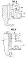
- FIG. 2 is a sectional view taken across a line II-II of FIG. 1 .
- FIG. 3 is a sectional view taken across a line III-III of FIG. 1 .
- FIG. 4 is a side view of a cylinder block according to a second embodiment of the present invention.
- FIG. 5 is a sectional view taken across a line V-V of FIG. 4 .
- FIG. 6 is a side view of a cylinder block according to a third embodiment of the present invention.
- FIG. 7 is a sectional view taken across a line VII-VII of FIG. 6 .
- FIGS. 1 ⁇ 3 show a cylinder block for an internal combustion engine, according to a first embodiment of the present invention.
- the internal combustion engine is an inline four-cylinder liquid-cooled engine adapted to be mounted transversely in a vehicle so that the intake side of the engine faces toward the front of the vehicle, and the exhaust side faces toward the rear of the vehicle.
- a cylinder block 10 shown in FIGS. 1 ⁇ 3 is a aluminum casting produced by aluminum die-casting process.
- Cylinder block 10 is formed with four cylinder walls 12 each defining a cylinder bore 11 in which a piston can reciprocate up and down.
- These four cylindrical cylinder walls 12 are shaped like a hollow cylinder, and arranged in a straight line extending in a cylinder row direction of the engine (in the left and right direction as viewed in FIG. 1 ). From the front end of cylinder block 10 (the left end of cylinder block 10 in FIG. 1 ) to the rear end (the right end in FIG. 1 ), the first to fourth cylinders are arranged in order of #1, #2, #3 and #4.
- Cylinder block 10 further includes a block wall (or jacket wall) including first and second (or front and rear) block side walls (jacket side walls) 14.
- the Block wall surrounds these cylinder walls 12, and defines a water jacket 18. Cooling water flows through water jacket 14 thus formed between the outer periphery of cylinder walls 12 and the block wall, and cools cylinder walls 12.
- Cylinder block 10 further includes a top deck 20 and a lower deck 22. Each cylinder wall 12 extends in an up-down direction of cylinder block 10, from top deck 20 to lower deck 22.
- one of the block side walls 14 is formed integrally with a cylindrical knock sensor mounting boss 60 to which a knock sensor is to be fixed, a tubular rib 68 extending in the cylinder row direction, and an accessory mounting flange 62 to which a thermostat as an accessory is to be attached.
- the block side wall 14 formed with mounting boss 60, tubular rib 68 and mounting flange 62 is the front (or intake side) block side wall 14 on the front side or intake side facing toward the front of a vehicle when engine block 10 is installed in the vehicle.
- the knock sensor is arranged to sense knocking in the cylinders #1 ⁇ #4, and provides a signal which is used by a control for a knocking preventing control such as retardation of the ignition timing.
- Accessory mounting flange 62 is formed with a plurality of bolt holes 64. An accessory fixing bolt is to be screwed into each bolt hole 64.
- Tubular rib 68 has therein a hollow cavity extending in the cylinder row direction, and tubular rib 68 is shaped like a tube.
- Tubular rib 68 is formed at an intermediate level between top deck 20 and lower deck 22, and bulged outward from the front block side wall 14.
- Tubular rib 68 is an integral part of the front block side wall 14.
- Tubular rib 68 extends in the cylinder row direction over two or more cylinders. In the example of FIG. 1 , tubular rib 68 extends over the second through third cylinders #2 ⁇ #4.
- tubular rib 68 of this example is formed in a thick wall portion in which an approximately cylindrical head bolt boss 36 is formed. This head bolt boss 36 is arranged to receive a head bolt for fixing a cylinder head to cylinder block 10.
- Tubular rib 68 of this example has therein a coolant passage 69, and serves as a water pipe for circulating cooling water.
- This coolant passage 69 is a cored hole formed by the casting process.
- Coolant passage 69 is opened in the rear end of cylinder block 10. The open end of coolant passage 69 is closed by a cap.
- Coolant passage 69 is connected fluidly with a first cooling water inlet/outlet port 72 formed in accessory mounting flange 62.
- a second cooling water inlet/outlet port 73 formed in accessory mounting flange 62 is connected fluidly with an auxiliary coolant passage 74 extending, in the up-down direction of cylinder block 10, to an upper end opening in top deck 20 and leading to a coolant passage in the cylinder head.
- Knock sensor mounting boss 60 is formed approximately at the middle between the length of cylinder block 10 in the cylinder row direction between the front and rear ends of cylinder block 10, as shown in FIG. 1 .
- knock sensor mounting boss 60 is located between the second cylinder #2 and the third cylinder #3.
- Knock sensor mounting boss 60 is cylindrical, and projects from the front cylinder block side wall 14, as shown in FIG. 2 .
- Knock sensor mounting boss 60 is an integral part of cylinder block side wall 14.
- knock sensor mounting boss 60 is formed between top deck 20 and tubular rib 68, and connected with tubular rib 68 by two connecting ribs 76 formed integrally in the block side wall 14.
- Connecting ribs 76 project from the block side wall 14, and extend in parallel to each other, in the up and down direction of cylinder block 10 like fins or bands. Connecting ribs 76 extend from knock sensor mounting boss 60 to tubular rib 68, and thereby connect the outer periphery of knock sensor mounting boss 60 and the outer periphery of tubular rib 68. Part of knock sensor mounting boss 60 is connected smoothly and integrally with top deck 20.
- tubular rib 68 having the inside cavity extends in the cylinder row direction over two or more cylinders, and knock sensor mounting boss 60 is connected with tubular rib 68. Therefore, vibrations of knocking in any of the cylinders can be transmitted effectively through tubular rib 68 to the knock sensor mounting boss 60 by the effect of resonance in the tubular rib 68, so that the knock sensor mounted on mounting boss 60 can detect knocking in any one or more of the cylinders accurately. Knocking in any of the cylinders can be detected effectively by a single knock sensor.
- Tubular rib 68 is formed with coolant passage 69 for circulation of cooling water, so that there is no need for attaching a water pipe to the cylinder block.
- the arrangement of integral tubular rib 68 is advantageous for simplification without the need for mounting bracket and seal member, cost reduction and weight reduction.
- tubular rib 68 is connected with accessory mounting flange 62 formed near the first cylinder #1.
- Tubular rib 68 terminates near the second cylinder #2, and the end of tubular rib 68 is connected with accessory mounting flange 62 having therein the coolant inlet/outlet ports 72 and 73, and auxiliary coolant passage 74.
- Accessory mounting flange 62 having these hollow portions can effectively transmit vibrations due to knocking in the first cylinder #1, by the effect of resonance like tubular rib 68.
- the knock sensor can detect knocking even in the first cylinder.
- Tubular rib 68 is cylindrical and the coolant passage 69 therein is circular as shown in FIG. 2 .
- tubular rib 68 may be square or rectangular, or shaped like some other figure.
- Tubular rib 68 extends in the cylinder row direction, so that it is possible to determine the position of knock sensor mounting boss 60 in the cylinder row direction more freely. Knocking in each of the cylinders can be sensed accurately by a knocking sensor disposed at any position in the cylinder row direction near tubular rib 68.
- FIGS, 4 and 5 schematically show a cylinder block according to a second embodiment of the present invention.
- the cylinder block shown in FIGS. 4 and 5 are substantially identical to the cylinder block of Figs. 1 ⁇ 3 , and repetitive explanation is omitted.
- tubular rib 68 extends over all the four cylinders #1 ⁇ #4 in the cylinder row direction from a first end to a second end.
- Accessory mounting flange 62 is formed in an intermediate position between the first and second ends of tubular rib 68.
- Knock sensor mounting boss 60 is connected integrally with tubular rib 68 by a single connecting rib 76 extending vertically and integrally from the knock sensor mounting boss 60 to tubular rib 68.
- tubular rib 68 extending over the entire cylinder row can function to transmit knocking vibrations effectively from any one of the cylinders in the row, securely to knock sensor mounting boss 60.
- FIGS, 6 and 7 schematically show a cylinder block according to a third embodiment of the present invention.
- tubular rib 68 extends over all the four cylinders #1 ⁇ #4 in the cylinder row direction, and accessory mounting flange 62 is formed in an intermediate position between the first and second ends of tubular rib 68.
- a knock sensor mounting boss 60 is connected directly with the outer circumference of tubular rib 68. Knock sensor mounting boss 60 overlaps tubular rib 68. A lower part of knock sensor mounting boss 60 is formed or buried in tubular rib 68. Knock sensor mounting boss 60 is located at a relatively low position and away from the top deck of the cylinder block.
- the third embodiment is advantageous in weight reduction and cost reduction as compared to the first and second embodiment.
- the present invention is not limited to the illustrated embodiments. Various modifications and variations are possible within the scope of the present invention. For example, the present invention is also applicable to an inline six-cylinder internal combustion engine.
Landscapes
- Engineering & Computer Science (AREA)
- Chemical & Material Sciences (AREA)
- Combustion & Propulsion (AREA)
- Mechanical Engineering (AREA)
- General Engineering & Computer Science (AREA)
- Cylinder Crankcases Of Internal Combustion Engines (AREA)
- Measurement Of Mechanical Vibrations Or Ultrasonic Waves (AREA)
- Combined Controls Of Internal Combustion Engines (AREA)
Claims (7)
- Zylinderblock mit einem Klopfsensor für eine Brennkraftmaschine, aufweisend:eine rohrförmige Rippe (68), die von einer Zylinderblock- Seitenwand (14) vorspringt, wobei sie sich in einer Richtung der Zylinderreihe über eine Mehrzahl von Zylindern erstreckt,gekennzeichnet durcheine Klopfsensor- Montagenabe (60), gebildet an der Zylinderblock- Seitenwand (14), wobei der Zylinderblock außerdem eine Verbindungsrippe (76) aufweist, die die rohrförmige Rippe (68) mit der Klopfsensor- Montagenabe (60) verbindet, oderwobei die Klopfsensor- Montagenabe (60) direkt mit einem Außenumfang der rohrförmigen Rippe (68) verbunden ist.
- Zylinderblock nach Anspruch 1, dadurch gekennzeichnet, dass die rohrförmige Rippe (68) darin einen Kühlmittelkanal (69) zum Zirkulieren von Kühlwasser hat.
- Zylinderblock nach Anspruch 1 oder 2, dadurch gekennzeichnet, dass der Zylinderblock einen zylinderbildenden Abschnitt (12) enthält, bildend eine Mehrzahl von Zylindern, angeordnet in einer gedachten Linie, die sich in der Richtung der Zylinderreihe erstreckt, eine obere Plattform (20), um an einem Zylinderkopf befestigt zu werden, und eine untere Plattform (22); wobei sich die rohrförmige Rippe (68) in der Richtung der Zylinderreihe zwischen der oberen Plattform (20) und der unteren Plattform (22) erstreckt; und die Klopfsensor- Montagenabe (60) zwischen der oberen Plattform (20) und der rohrförmigen Rippe gebildet ist.
- Zylinderblock nach einem der Ansprüche 1 bis 3, dadurch gekennzeichnet, dass die rohrförmige Rippe (68) und die Klopfsensor- Montagenabe (60) an einer äußeren Seite eines Kopfschraubennabe (36), gebildet mit einer Schraubenbohrung zum Aufnehmen einer Zylinderkopfschraube zum Befestigen eines Zylinderkopfes an der oberen Plattform des Zylinderblocks, gebildet sind.
- Zylinderblock nach einem der Ansprüche 1 bis 4, dadurch gekennzeichnet, dass der Zylinderblock außerdem einen Montageflansch (62) aufweist, der sich in Richtung der Zylinderreihe von einer der rohrförmigen Rippe (68) erstreckt und einen hohle Formhohlraum (72) enthält; wobei die rohrförmige Rippe mit dem Montageflansch verbunden ist; und der hohle Formhohlraum der rohrförmigen Rippe (68) mit dem hohlen Formhohlraum des Montageflanschs (62) verbunden ist.
- Zylinderblock nach einem der Ansprüche 1 bis 5, dadurch gekennzeichnet, dass der Zylinderblock ein einstückiges Gußstück ist und die Klopfsensor- Montagenabe (60) und die rohrförmige Rippe (68) beides integrale Teile des Gussstückes sind.
- Zylinderblock nach einem der Ansprüche 1 bis 4, dadurch gekennzeichnet, dass die Klopfsensor- Montagenabe (60) einen unteren Abschnitt, gebildet in der rohrförmigen Rippe (68), enthält.
Applications Claiming Priority (2)
| Application Number | Priority Date | Filing Date | Title |
|---|---|---|---|
| JP2003351580 | 2003-10-10 | ||
| JP2003351580A JP4305118B2 (ja) | 2003-10-10 | 2003-10-10 | 内燃機関のシリンダブロック |
Publications (3)
| Publication Number | Publication Date |
|---|---|
| EP1522705A2 EP1522705A2 (de) | 2005-04-13 |
| EP1522705A3 EP1522705A3 (de) | 2005-04-27 |
| EP1522705B1 true EP1522705B1 (de) | 2011-04-27 |
Family
ID=34309269
Family Applications (1)
| Application Number | Title | Priority Date | Filing Date |
|---|---|---|---|
| EP04023827A Expired - Lifetime EP1522705B1 (de) | 2003-10-10 | 2004-10-06 | Zylinderblock für eine Brennkraftmaschine |
Country Status (5)
| Country | Link |
|---|---|
| US (1) | US7171928B2 (de) |
| EP (1) | EP1522705B1 (de) |
| JP (1) | JP4305118B2 (de) |
| CN (1) | CN100591907C (de) |
| DE (1) | DE602004032412D1 (de) |
Families Citing this family (9)
| Publication number | Priority date | Publication date | Assignee | Title |
|---|---|---|---|---|
| JP4654949B2 (ja) * | 2006-03-13 | 2011-03-23 | 日産自動車株式会社 | 内燃機関の燃料系保護構造 |
| US8466096B2 (en) * | 2007-04-26 | 2013-06-18 | Afton Chemical Corporation | 1,3,2-dioxaphosphorinane, 2-sulfide derivatives for use as anti-wear additives in lubricant compositions |
| JP2013024101A (ja) * | 2011-07-20 | 2013-02-04 | Yamaha Motor Co Ltd | 内燃機関およびそれを備えた鞍乗型車両 |
| JP2013024100A (ja) * | 2011-07-20 | 2013-02-04 | Yamaha Motor Co Ltd | 内燃機関およびそれを備えた鞍乗型車両 |
| JP2013024099A (ja) | 2011-07-20 | 2013-02-04 | Yamaha Motor Co Ltd | 内燃機関およびそれを備えた鞍乗型車両 |
| US9442034B2 (en) * | 2013-11-22 | 2016-09-13 | Ford Global Technologies, Llc | Engine knock signal transmissive element |
| JP2016011587A (ja) * | 2014-06-27 | 2016-01-21 | 本田技研工業株式会社 | ユニットスイングエンジンにおけるノックセンサ取付け構造 |
| DE102018211169A1 (de) * | 2018-07-06 | 2020-01-09 | Bayerische Motoren Werke Aktiengesellschaft | Verbrennungskraftmaschine für ein Kraftfahrzeug, insbesondere für einen Kraftwagen, sowie Kraftfahrzeug |
| CN110567727B (zh) * | 2019-08-13 | 2021-10-01 | 北京化工大学 | 一种基于振动加速度信号的柴油机输出功率评估方法 |
Family Cites Families (11)
| Publication number | Priority date | Publication date | Assignee | Title |
|---|---|---|---|---|
| JPS58111364U (ja) * | 1982-01-26 | 1983-07-29 | 日産自動車株式会社 | ノツキング回避装置 |
| JPS61117418A (ja) | 1984-11-14 | 1986-06-04 | Nissan Motor Co Ltd | ノツキングセンサの取付構造 |
| JPH0672527B2 (ja) * | 1989-02-13 | 1994-09-14 | 本田技研工業株式会社 | シリンダブロックの潤滑油通路構造 |
| JP2503465Y2 (ja) * | 1990-03-31 | 1996-07-03 | マツダ株式会社 | エンジンのブロック構造 |
| JP2751771B2 (ja) | 1992-12-25 | 1998-05-18 | 三菱自動車工業株式会社 | 直列多気筒エンジンのシリンダブロック |
| DE19628762A1 (de) * | 1996-07-17 | 1998-01-22 | Porsche Ag | Kühlkreislauf einer Brennkraftmaschine |
| JP2000145451A (ja) * | 1998-11-13 | 2000-05-26 | Sanshin Ind Co Ltd | 筒内燃料噴射式2サイクルエンジンの冷却構造 |
| JP4049344B2 (ja) * | 1998-12-17 | 2008-02-20 | ヤマハマリン株式会社 | 筒内燃料噴射式エンジン |
| JP2001115836A (ja) | 1999-10-19 | 2001-04-24 | Mazda Motor Corp | 水冷式エンジンの本体構造 |
| JP3903744B2 (ja) | 2001-06-06 | 2007-04-11 | 三菱自動車工業株式会社 | エンジンの冷却構造 |
| JP2003322054A (ja) | 2002-05-07 | 2003-11-14 | Mazda Motor Corp | エンジンのノックセンサ取付構造 |
-
2003
- 2003-10-10 JP JP2003351580A patent/JP4305118B2/ja not_active Expired - Lifetime
-
2004
- 2004-10-05 US US10/957,703 patent/US7171928B2/en not_active Expired - Lifetime
- 2004-10-06 EP EP04023827A patent/EP1522705B1/de not_active Expired - Lifetime
- 2004-10-06 DE DE602004032412T patent/DE602004032412D1/de not_active Expired - Lifetime
- 2004-10-10 CN CN200410084942A patent/CN100591907C/zh not_active Expired - Lifetime
Also Published As
| Publication number | Publication date |
|---|---|
| CN100591907C (zh) | 2010-02-24 |
| EP1522705A2 (de) | 2005-04-13 |
| JP4305118B2 (ja) | 2009-07-29 |
| US20050076860A1 (en) | 2005-04-14 |
| US7171928B2 (en) | 2007-02-06 |
| EP1522705A3 (de) | 2005-04-27 |
| DE602004032412D1 (de) | 2011-06-09 |
| CN1605735A (zh) | 2005-04-13 |
| JP2005113849A (ja) | 2005-04-28 |
Similar Documents
| Publication | Publication Date | Title |
|---|---|---|
| US6513506B1 (en) | Cylinder head structure in multi-cylinder engine | |
| US6729272B2 (en) | Cylinder head cooling construction for an internal combustion engine | |
| EP1522705B1 (de) | Zylinderblock für eine Brennkraftmaschine | |
| JP2002070609A (ja) | 多気筒エンジン | |
| US7128029B2 (en) | Water-cooled cylinder head for a multicylinder internal-combustion engine | |
| CN108952988B (zh) | 气缸盖结构 | |
| KR100325032B1 (ko) | 다기통 엔진의 실린더헤드 구조 | |
| US6959687B2 (en) | SOHC type engine | |
| JP3866473B2 (ja) | シリンダブロックのスリーブ構造 | |
| US7128028B2 (en) | Water-cooled cylinder head for a multicylinder internal-combustion engine | |
| US7100545B2 (en) | Cylinder head for a water-cooled internal combustion piston engine having inner reinforcement | |
| JP2000220521A (ja) | エンジンのシリンダヘッドカバー | |
| JP3959703B2 (ja) | エンジンのノックセンサ取付構造 | |
| JP4791304B2 (ja) | 水冷式エンジン | |
| JPH0639078Y2 (ja) | 内燃機関のシリンダヘッドの冷却水通路構造 | |
| JPS6018570Y2 (ja) | 内燃機関の排気マニホ−ルド取付装置 | |
| CN219220581U (zh) | 一种摩托车风冷气缸头结构 | |
| JP3885259B2 (ja) | エンジンの冷却装置 | |
| JPH088290Y2 (ja) | 内燃機関の一体型シリンダブロック | |
| JPH0442508Y2 (de) | ||
| JP2007187107A (ja) | 内燃機関 | |
| KR100412736B1 (ko) | 엔진의 오일 드레인/블로 바이 시스템 | |
| JP2008231934A (ja) | 頭上四弁式多気筒内燃機関におけるシリンダヘッド | |
| JP2005226572A (ja) | 可変圧縮比内燃機関 | |
| CN106471236A (zh) | 内燃机 |
Legal Events
| Date | Code | Title | Description |
|---|---|---|---|
| PUAI | Public reference made under article 153(3) epc to a published international application that has entered the european phase |
Free format text: ORIGINAL CODE: 0009012 |
|
| PUAL | Search report despatched |
Free format text: ORIGINAL CODE: 0009013 |
|
| 17P | Request for examination filed |
Effective date: 20041006 |
|
| AK | Designated contracting states |
Kind code of ref document: A2 Designated state(s): AT BE BG CH CY CZ DE DK EE ES FI FR GB GR HU IE IT LI LU MC NL PL PT RO SE SI SK TR |
|
| AX | Request for extension of the european patent |
Extension state: AL HR LT LV MK |
|
| AK | Designated contracting states |
Kind code of ref document: A3 Designated state(s): AT BE BG CH CY CZ DE DK EE ES FI FR GB GR HU IE IT LI LU MC NL PL PT RO SE SI SK TR |
|
| AX | Request for extension of the european patent |
Extension state: AL HR LT LV MK |
|
| RIC1 | Information provided on ipc code assigned before grant |
Ipc: 7F 02B 77/08 B Ipc: 7F 02F 7/00 A Ipc: 7F 02F 1/10 B Ipc: 7F 01P 11/04 B |
|
| AKX | Designation fees paid |
Designated state(s): DE FR GB |
|
| 17Q | First examination report despatched |
Effective date: 20051222 |
|
| GRAP | Despatch of communication of intention to grant a patent |
Free format text: ORIGINAL CODE: EPIDOSNIGR1 |
|
| GRAS | Grant fee paid |
Free format text: ORIGINAL CODE: EPIDOSNIGR3 |
|
| GRAA | (expected) grant |
Free format text: ORIGINAL CODE: 0009210 |
|
| AK | Designated contracting states |
Kind code of ref document: B1 Designated state(s): DE FR GB |
|
| REG | Reference to a national code |
Ref country code: GB Ref legal event code: FG4D |
|
| REF | Corresponds to: |
Ref document number: 602004032412 Country of ref document: DE Date of ref document: 20110609 Kind code of ref document: P |
|
| REG | Reference to a national code |
Ref country code: DE Ref legal event code: R096 Ref document number: 602004032412 Country of ref document: DE Effective date: 20110609 |
|
| PLBE | No opposition filed within time limit |
Free format text: ORIGINAL CODE: 0009261 |
|
| STAA | Information on the status of an ep patent application or granted ep patent |
Free format text: STATUS: NO OPPOSITION FILED WITHIN TIME LIMIT |
|
| 26N | No opposition filed |
Effective date: 20120130 |
|
| REG | Reference to a national code |
Ref country code: DE Ref legal event code: R097 Ref document number: 602004032412 Country of ref document: DE Effective date: 20120130 |
|
| REG | Reference to a national code |
Ref country code: FR Ref legal event code: PLFP Year of fee payment: 13 |
|
| REG | Reference to a national code |
Ref country code: FR Ref legal event code: PLFP Year of fee payment: 14 |
|
| REG | Reference to a national code |
Ref country code: FR Ref legal event code: PLFP Year of fee payment: 15 |
|
| PGFP | Annual fee paid to national office [announced via postgrant information from national office to epo] |
Ref country code: GB Payment date: 20230920 Year of fee payment: 20 |
|
| PGFP | Annual fee paid to national office [announced via postgrant information from national office to epo] |
Ref country code: FR Payment date: 20230920 Year of fee payment: 20 |
|
| PGFP | Annual fee paid to national office [announced via postgrant information from national office to epo] |
Ref country code: DE Payment date: 20230920 Year of fee payment: 20 |
|
| REG | Reference to a national code |
Ref country code: DE Ref legal event code: R071 Ref document number: 602004032412 Country of ref document: DE |
|
| REG | Reference to a national code |
Ref country code: GB Ref legal event code: PE20 Expiry date: 20241005 |
|
| PG25 | Lapsed in a contracting state [announced via postgrant information from national office to epo] |
Ref country code: GB Free format text: LAPSE BECAUSE OF EXPIRATION OF PROTECTION Effective date: 20241005 |
|
| PG25 | Lapsed in a contracting state [announced via postgrant information from national office to epo] |
Ref country code: GB Free format text: LAPSE BECAUSE OF EXPIRATION OF PROTECTION Effective date: 20241005 |