EP1522508B2 - Dispositif de séparation, de synchronisation et d'accumulation - Google Patents
Dispositif de séparation, de synchronisation et d'accumulation Download PDFInfo
- Publication number
- EP1522508B2 EP1522508B2 EP04018531A EP04018531A EP1522508B2 EP 1522508 B2 EP1522508 B2 EP 1522508B2 EP 04018531 A EP04018531 A EP 04018531A EP 04018531 A EP04018531 A EP 04018531A EP 1522508 B2 EP1522508 B2 EP 1522508B2
- Authority
- EP
- European Patent Office
- Prior art keywords
- speed
- driving elements
- main conveyor
- pair
- conveyor
- Prior art date
- Legal status (The legal status is an assumption and is not a legal conclusion. Google has not performed a legal analysis and makes no representation as to the accuracy of the status listed.)
- Expired - Lifetime
Links
- 230000033001 locomotion Effects 0.000 claims description 32
- 238000000034 method Methods 0.000 claims description 14
- 238000011161 development Methods 0.000 claims description 4
- 238000012856 packing Methods 0.000 claims 1
- 230000008901 benefit Effects 0.000 description 7
- 238000005056 compaction Methods 0.000 description 7
- 230000006835 compression Effects 0.000 description 7
- 238000007906 compression Methods 0.000 description 7
- 230000008859 change Effects 0.000 description 5
- 238000004806 packaging method and process Methods 0.000 description 5
- 230000015572 biosynthetic process Effects 0.000 description 4
- 238000013461 design Methods 0.000 description 3
- 230000002028 premature Effects 0.000 description 3
- 230000001360 synchronised effect Effects 0.000 description 3
- 230000000712 assembly Effects 0.000 description 2
- 238000000429 assembly Methods 0.000 description 2
- 238000010586 diagram Methods 0.000 description 2
- 238000006073 displacement reaction Methods 0.000 description 2
- 239000002184 metal Substances 0.000 description 2
- 230000004913 activation Effects 0.000 description 1
- 238000006243 chemical reaction Methods 0.000 description 1
- 230000018109 developmental process Effects 0.000 description 1
- 238000007598 dipping method Methods 0.000 description 1
- 230000000694 effects Effects 0.000 description 1
- 238000011156 evaluation Methods 0.000 description 1
- 230000001747 exhibiting effect Effects 0.000 description 1
- 238000004519 manufacturing process Methods 0.000 description 1
- 239000000463 material Substances 0.000 description 1
- 238000012806 monitoring device Methods 0.000 description 1
- 238000012858 packaging process Methods 0.000 description 1
- 230000008569 process Effects 0.000 description 1
- 238000012545 processing Methods 0.000 description 1
- 230000009467 reduction Effects 0.000 description 1
- 230000000717 retained effect Effects 0.000 description 1
- 229920006300 shrink film Polymers 0.000 description 1
Images


Classifications
-
- B—PERFORMING OPERATIONS; TRANSPORTING
- B65—CONVEYING; PACKING; STORING; HANDLING THIN OR FILAMENTARY MATERIAL
- B65G—TRANSPORT OR STORAGE DEVICES, e.g. CONVEYORS FOR LOADING OR TIPPING, SHOP CONVEYOR SYSTEMS OR PNEUMATIC TUBE CONVEYORS
- B65G17/00—Conveyors having an endless traction element, e.g. a chain, transmitting movement to a continuous or substantially-continuous load-carrying surface or to a series of individual load-carriers; Endless-chain conveyors in which the chains form the load-carrying surface
- B65G17/26—Conveyors having an endless traction element, e.g. a chain, transmitting movement to a continuous or substantially-continuous load-carrying surface or to a series of individual load-carriers; Endless-chain conveyors in which the chains form the load-carrying surface comprising a series of co-operating units, e.g. interconnected by pivots
-
- B—PERFORMING OPERATIONS; TRANSPORTING
- B65—CONVEYING; PACKING; STORING; HANDLING THIN OR FILAMENTARY MATERIAL
- B65G—TRANSPORT OR STORAGE DEVICES, e.g. CONVEYORS FOR LOADING OR TIPPING, SHOP CONVEYOR SYSTEMS OR PNEUMATIC TUBE CONVEYORS
- B65G47/00—Article or material-handling devices associated with conveyors; Methods employing such devices
- B65G47/02—Devices for feeding articles or materials to conveyors
- B65G47/04—Devices for feeding articles or materials to conveyors for feeding articles
- B65G47/06—Devices for feeding articles or materials to conveyors for feeding articles from a single group of articles arranged in orderly pattern, e.g. workpieces in magazines
- B65G47/08—Devices for feeding articles or materials to conveyors for feeding articles from a single group of articles arranged in orderly pattern, e.g. workpieces in magazines spacing or grouping the articles during feeding
- B65G47/084—Devices for feeding articles or materials to conveyors for feeding articles from a single group of articles arranged in orderly pattern, e.g. workpieces in magazines spacing or grouping the articles during feeding grouping articles in a predetermined 2-dimensional pattern
- B65G47/086—Devices for feeding articles or materials to conveyors for feeding articles from a single group of articles arranged in orderly pattern, e.g. workpieces in magazines spacing or grouping the articles during feeding grouping articles in a predetermined 2-dimensional pattern cubiform articles
-
- B—PERFORMING OPERATIONS; TRANSPORTING
- B65—CONVEYING; PACKING; STORING; HANDLING THIN OR FILAMENTARY MATERIAL
- B65G—TRANSPORT OR STORAGE DEVICES, e.g. CONVEYORS FOR LOADING OR TIPPING, SHOP CONVEYOR SYSTEMS OR PNEUMATIC TUBE CONVEYORS
- B65G47/00—Article or material-handling devices associated with conveyors; Methods employing such devices
- B65G47/22—Devices influencing the relative position or the attitude of articles during transit by conveyors
- B65G47/26—Devices influencing the relative position or the attitude of articles during transit by conveyors arranging the articles, e.g. varying spacing between individual articles
- B65G47/30—Devices influencing the relative position or the attitude of articles during transit by conveyors arranging the articles, e.g. varying spacing between individual articles during transit by a series of conveyors
- B65G47/32—Applications of transfer devices
-
- B—PERFORMING OPERATIONS; TRANSPORTING
- B65—CONVEYING; PACKING; STORING; HANDLING THIN OR FILAMENTARY MATERIAL
- B65G—TRANSPORT OR STORAGE DEVICES, e.g. CONVEYORS FOR LOADING OR TIPPING, SHOP CONVEYOR SYSTEMS OR PNEUMATIC TUBE CONVEYORS
- B65G47/00—Article or material-handling devices associated with conveyors; Methods employing such devices
- B65G47/74—Feeding, transfer, or discharging devices of particular kinds or types
- B65G47/84—Star-shaped wheels or devices having endless travelling belts or chains, the wheels or devices being equipped with article-engaging elements
- B65G47/841—Devices having endless travelling belts or chains equipped with article-engaging elements
-
- B—PERFORMING OPERATIONS; TRANSPORTING
- B65—CONVEYING; PACKING; STORING; HANDLING THIN OR FILAMENTARY MATERIAL
- B65G—TRANSPORT OR STORAGE DEVICES, e.g. CONVEYORS FOR LOADING OR TIPPING, SHOP CONVEYOR SYSTEMS OR PNEUMATIC TUBE CONVEYORS
- B65G2201/00—Indexing codes relating to handling devices, e.g. conveyors, characterised by the type of product or load being conveyed or handled
- B65G2201/02—Articles
- B65G2201/0235—Containers
- B65G2201/0244—Bottles
Definitions
- the present invention relates to a device for dividing, synchronizing and compacting articles according to the preamble of claim 1.
- Devices of this type are required within packaging machines to form individual article groups or articles from article streams flowing in closed rows, which are subsequently packaged in cartons, boxes, trays and / or shrink film.
- This packaging process consists of several sub-processes, whereby it is state of the art to use individual machines for the implementation of these sub-processes, but at least individual, closed assemblies or modules.
- the article stream which will be containers or goods of all kinds, e.g. Bottles, bags, cans, cartons, pouches, etc. can be supplied through a feed dog of the compartment device.
- this conveyor is usually a, equipped with a wide conveyor belt device, which is additionally equipped with guides made of sheet metal, which form over the conveyor belt arranged lanes.
- the desired quantity of articles is divided by the article stream standing in abutment in the individual lanes, the quantity of articles resulting from the multiplication of the number of rows in the running direction by the number of rows transversely to the running direction.
- the next process step is the so-called compaction, which serves to close the gaps created within the format by the guides and possible displacements of the articles.
- the format is moved by means of a suitable device by narrowing outer guides, whereby the gaps generated by the guides are closed.
- the format is removed from the feed dog and pushed onto a stationary sheet, with the result that the gaps in the running direction within the rows are likewise closed.
- this synchronization device consists of both sides of the container stream arranged, parallel, synchronously driven chains, wherein these rods are arranged a plurality of bars such that these bars extend transversely to the transport direction and thus take along the articles by their forward movement and synchronize.
- a special feature of this device is to note that at the beginning of the synchronization two pairs of chains interlock, whereby initially each individual article row is transported by its own cross bar. After a certain distance one of the two pairs of chains is led out of the flow of articles, so that in the further course of the route only the remaining pair of chains performs the subsequent compression and synchronization, which also has the consequence that several transverse rows (rows of articles transverse to the direction) of a Cross bar are transported, whereby finally the actual format is formed.
- a disadvantage of such a device is that a change of the generated format only by the assembly or disassembly of numerous crossbars is possible.
- not all desired formats can be generated by the intermeshing of the two pairs of chains and the other structural features of the device.
- each guideway On each guideway is a so-called linear slide, which is provided with retractable and retractable retaining levers.
- All linear slides are each driven by a drive chain connected to them, wherein all linear slides of a set or a height level are driven by a common servomotor and moved synchronously.
- the department of article groups is made by a first set of linear slide with extended retaining levers makes a forward movement, while retaining the nachdrteilenden article flow against the higher-speed conveyor belt. At the same time, a second set of linear slides with retracted retaining levers makes a backward movement.
- the retaining levers are extended, whereby an article group is separated from the article flow. If the retaining levers are extended, the first set of linear slides releases the leading edge of the just-formed article group, which is then transported further at the higher conveyor belt speed and thus can simultaneously form a gap to the following article stream retained by the second set of linear slides ,
- a disadvantage of such a device is that the article stream, which in most cases is already close together, must first be separated, since the linear carriages are inter alia arranged between the individual longitudinal rows. Further difficulties arise due to this arrangement in that in the context of compression very large gaps must be reduced, which leads selbiger in particular with tilt-sensitive articles to frequent overturning, which is extremely undesirable in practice.
- the object and purpose of the present invention is to obviate the drawbacks presented above and to provide a device which makes it possible to significantly reduce the required costs, the number of components and the space requirement.
- the compartment unit and the compression / synchronization unit to form a unit together. This problem is solved by the characterizing features of claim 1.
- At least one pair of drive elements 1 is provided, on which at least one transverse bar 2 is arranged.
- drive elements may be e.g. to chains made of metal or other suitable material, in particular to act so-called roller link chains.
- toothed belt is provided, in particular such toothed belts are provided, which can be fixed by means of suitable elements of the above-mentioned transverse bar 2.
- a pair of drive elements 1 are to be understood as the drive elements which are driven by a common drive motor and wherein one of these drive elements 1 is on the left and a drive element 1 is located on the right of the path of the article groups to be split off or already divided.
- Each of the pairs of drive elements 1 is driven by its own motor 3, with this motor e.g. can be an electrically operated stepper, servo or synchronous motor. It is common to all types of motors that rotation angle, direction of rotation and rotation speed are specified by a computer or other suitable control device and that compliance with these target values by suitable monitoring devices such. Encoders monitored and further reported for subsequent evaluation.
- the rotational speed and / or direction of rotation of the motor and thus also movement speed and / or direction of movement of the motor driven by this pair of drive elements 1 also within one or a half revolution of the drive elements 1 to different Target values can be adjusted.
- the speed of movement of the drive elements 1 can also reach the value of zero m / s, this value of the speed is not only forcibly achieved during a possible change of the direction of movement, but also can be specified for a specific time interval.
- the length of a working cycle is determined by the number of transverse rods 2 mounted on a pair of drive elements 1. If in each case only one transverse bar 2 is mounted, then one working cycle corresponds to one revolution of the drive elements 1. If, on the other hand, two transverse bars 2 are mounted, then one working cycle corresponds to half a revolution of the drive elements 1.
- the structural design was made such that the individual drive elements 1, due to the arranged on a common height level cross bars 2, can not overtake each other.
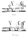
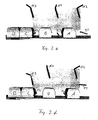
- FIG. 2 is shown in the individual diagrams 2a to 2g of the particularly advantageous movement of the present invention.
- it has been dispensed with individually to depict the articles to be packaged, for example bottles in the present exemplary embodiment. Instead, only the enveloping body of the divided or subsequently still be divided article groups (eg Fig. 2a , Pos B and C, or Fig. 2d , Pos C and D).
- FIG. 2 was dispensed with an explicit representation of the three drive elements 1, it was shown in a schematic diagram, only the trajectory 4 of the drive elements 1.
- the attached to the three drive elements 1 cross bars 2 were marked according to their affiliation to a drive elements 1.
- the cross bars 2 with the marking K2 are fastened to the second drive element 1, the transverse bars 2 with the marking K3 correspondingly to the third drive element 1.
- the articles to be separated and synchronized are fed to the compartment, synchronization and compacting device by an infeed conveyor 5, the articles being permanently held under dynamic pressure by continuously conveying the infeed conveyor 5 within the compartment unit and thus striving to move in the conveying direction.
- the articles are first fed by the infeed conveyor 5 onto a fixed, non-moving component, e.g. a sheet 8 or similar, postponed.
- a push-on wedge 7 which performs a controlled movement. This sequence of movements consists of a forward and backward movement, each with different, not necessarily constant speeds and possibly, additional defined standstill phases together.
- the main conveyor 6 connects.
- This main conveyor 6 is operated at a constant speed which is greater than that of the inlet conveyor 5.
- the subsequent stream of articles is held by the inlet conveyor 5 under dynamic pressure, so that the subsequently divested article groups B and C initially connect to each other gapless.
- the pusher wedge 7 assumes an important function. During the forward movement of the tapering article flow of the pusher wedge 7 also extends and carries during this forward movement, the article group B to be split, thereby preventing this group of articles comes into contact with the main conveyor 6.
- the length of the article group to be split is greater than the effective length of the slip wedge 7, so is already a part of the article group on the main conveyor 6, so prevents the moving with the speed of the inlet conveyor 5 transverse bar K1 gap formation within this group of items.
- the push-on wedge 7 effects a backward movement, whereby the entire article group B to be separated is placed on the main conveyor 6 and thus assumes the higher speed of the main conveyor 6. Since also the cross bar K1 assumes the higher speed of the main conveyor 6 at this time, the desired gap formation occurs for the following article group C.
- the backward movement of the pusher wedge 7 ends at the front edge of the subsequently classified article group C. If this front edge is reached, then the pusher wedge 7 follows the forward movement of the article group C, where it executes them at the same speed as the article group C (see Fig. 2b ).
- the next transverse bar 2, here K2 plunges into the resulting gap and prevents premature gap formation within the following article group C, with the transverse bar K2 moving essentially in line with the speed of the inlet conveyor 5 after being immersed in the gap ,
- the pusher wedge 7 continues to move out, wherein it continues to maintain contact with the front edge of the article group C and prevents this article group from coming into contact with the main conveyor 6.
- the cross bar K1 is moved as long with a relation to the main conveyor 6 increased speed until the cross bar reaches the back of the previous article group A.
- the transverse rod K1 again assumes the speed of the main conveyor 6 and pushes the article group A through the compression unit, not shown.
- compaction units are state of the art and usually consist of guide plates arranged on both sides of the path of the article group, which form a funnel-shaped bottleneck, whereby gaps existing within the transverse rows of the article group are closed. Gaps present within the longitudinal rows are created by sliding the article group onto a fixed component, e.g. a sheet, closed, the cross bar K1 causes the forward movement of the article group by pushing.
- a fixed component e.g. a sheet
- compartment, synchronization and compression station are realized in only one module, resulting from the highly advantageous embodiment of the present invention further advantages.
Landscapes
- Engineering & Computer Science (AREA)
- Mechanical Engineering (AREA)
- Attitude Control For Articles On Conveyors (AREA)
- Auxiliary Devices For And Details Of Packaging Control (AREA)
- Specific Conveyance Elements (AREA)
Claims (17)
- Dispositif de séparation, de synchronisation et d'accumulation pour le conditionnement d'articles de tout genre, comportant au moins un convoyeur d'entrée (5), au moins une cale d'admission (7), au moins un convoyeur principal (6) et au moins une unité d'accumulation, la vitesse du convoyeur principal (6) étant supérieure à celle du convoyeur d'entrée, comportant au moins une paire d'éléments d'entraînement (1), agencés de manière à défiler, comportant au moins une barre transversale (2) montée sur chaque paire d'éléments d'entraînement (1), comportant respectivement un moteur d'entraînement (3) commandé pour chaque paire d'éléments d'entraînement (1), caractérisé en ce qu'au moins une paire d'éléments d'entraînement (1) comporte une trajectoire de déplacement commandée, possédant différentes vitesses, le dispositif étant construit de telle sorte que la séparation est réalisée par la cale d'admission (7) mobile vers l'avant et l'arrière et la synchronisation et l'accumulation des articles est assurée par la paire d'éléments d'entraînement (1), au nombre d'au moins une, et la vitesse du convoyeur principal (6) étant constante.
- Dispositif selon la revendication 1, caractérisé en ce que la configuration constructive du dispositif est telle que les barres transversales (2), montées sur les différentes paires d'éléments d'entraînement (1), ne peuvent pas se dépasser mutuellement.
- Dispositif selon la revendication 1 ou 2, caractérisé en ce que la configuration constructive du dispositif est telle que les barres transversales (2), montées sur les différentes paires d'éléments d'entraînement (1), peuvent se dépasser mutuellement.
- Dispositif selon l'une des revendications 1 à 3, caractérisé en ce qu'au moins une des paires d'éléments d'entraînement (1) est formée par des chaînes.
- Dispositif selon l'une des revendications 1 à 3, caractérisé en ce qu'au moins une des paires d'éléments d'entraînement (1) est formée par des courroies dentées.
- Dispositif selon l'une des revendications 1 à 5, caractérisé en ce que le dispositif comporte des moyens qui permettent d'effectuer le mouvement vers l'avant et le mouvement vers l'arrière de la cale d'admission (7) avec différentes vitesses commandées.
- Dispositif selon l'une des revendications 1 à 6, caractérisé en ce que le convoyeur d'entrée (5), de même que le convoyeur principal (6) sont équipés avec leur propre moteur d'entraînement.
- Dispositif selon l'une des revendications 1 à 7, caractérisé en ce que le convoyeur principal (6) est réalisé sous forme de large bande de transport d'une seule pièce ayant une surface sensiblement fermée.
- Procédé de fonctionnement d'un dispositif selon l'une des revendications 1 à 8, caractérisé en ce que la trajectoire de déplacement de ladite au moins une paire d'éléments d'entraînement (1) et/ou de ladite au moins une barre transversale (2) a des vitesses différentes pendant un cycle de travail.
- Procédé selon la revendication 9, caractérisé en ce que ladite au moins une barre transversale (2) retient d'abord par rapport au convoyeur principal (6) les groupes d'articles à séparer, se déplace ensuite avec une vitesse plus élevée, synchronise les groupes d'articles précédemment séparés une fois que ceux-ci ont atteint la cadence de travail du dispositif et pousse ensuite ces groupes d'articles à travers une unité d'accumulation.
- Procédé selon la revendication 10, caractérisé en ce que, après la séparation d'un groupe d'articles, ladite au moins une barre transversale (2) se déplace d'abord avec une vitesse analogue à celle du convoyeur principal (6), se déplace ensuite avec une vitesse plus élevée, et se déplace ensuite à nouveau avec une vitesse analogue à celle du convoyeur principal (6).
- Dispositif selon l'une des revendications 9 à 11, caractérisé en ce que l'adaptation du dispositif à des formats modifiés et/ou des dimensions d'articles modifiées sans que le nombre de rangées transversales ait été modifié est effectuée exclusivement par la variation des paramètres de commande à l'intérieur du programme de commande et/ou de la commande du dispositif.
- Dispositif selon la revendication 12, caractérisé en ce que les paramètres de commande significatifs pour chaque format et/ou dimension d'article sont mémorisés et peuvent être chargés de manière ciblée.
- Dispositif selon l'une des revendications 9 à 13, caractérisé en ce que la cale d'admission (7) effectue un mouvement d'avance et un mouvement de recul.
- Dispositif selon la revendication 14, caractérisé en ce que la cale d'admission (7) effectue le mouvement d'avance avec une première vitesse et le mouvement de recul avec une deuxième vitesse.
- Dispositif selon la revendication 15, caractérisé en ce que la première et la deuxième vitesse sont identiques.
- Dispositif selon l'une des revendications 9 à 16, caractérisé en ce que le convoyeur d'entrée (5) et le convoyeur principal (6) sont entraînés chacun avec leurs propres vitesses, indépendantes l'une de l'autre.
Priority Applications (1)
| Application Number | Priority Date | Filing Date | Title |
|---|---|---|---|
| PL04018531T PL1522508T5 (pl) | 2003-10-09 | 2004-08-05 | Urządzenie do oddzielania synchronizacji i zagęszczania |
Applications Claiming Priority (2)
| Application Number | Priority Date | Filing Date | Title |
|---|---|---|---|
| DE10347540A DE10347540B4 (de) | 2003-10-09 | 2003-10-09 | Abteil-, Synchronisations- und Verdichtungsvorrichtung |
| DE10347540 | 2003-10-09 |
Publications (3)
| Publication Number | Publication Date |
|---|---|
| EP1522508A1 EP1522508A1 (fr) | 2005-04-13 |
| EP1522508B1 EP1522508B1 (fr) | 2007-01-17 |
| EP1522508B2 true EP1522508B2 (fr) | 2009-11-11 |
Family
ID=34306386
Family Applications (1)
| Application Number | Title | Priority Date | Filing Date |
|---|---|---|---|
| EP04018531A Expired - Lifetime EP1522508B2 (fr) | 2003-10-09 | 2004-08-05 | Dispositif de séparation, de synchronisation et d'accumulation |
Country Status (7)
| Country | Link |
|---|---|
| US (2) | US20050108992A1 (fr) |
| EP (1) | EP1522508B2 (fr) |
| JP (1) | JP2005112470A (fr) |
| AU (1) | AU2004218712B2 (fr) |
| DE (2) | DE10347540B4 (fr) |
| PL (1) | PL1522508T5 (fr) |
| ZA (1) | ZA200407043B (fr) |
Families Citing this family (24)
| Publication number | Priority date | Publication date | Assignee | Title |
|---|---|---|---|---|
| DE602005008703D1 (de) * | 2005-02-04 | 2008-09-18 | Tetra Laval Holdings & Finance | Gerät zur Gruppierung von Verpackungen entlang einen Arbeitsweg |
| DE102005026639B4 (de) | 2005-06-09 | 2009-01-08 | Khs Ag | Vorrichtung zum Aufteilen, Eintakten und Gruppieren von Stückgütern |
| DE102005063193B4 (de) * | 2005-12-30 | 2018-05-03 | Krones Aktiengesellschaft | Vorrichtung und Verfahren zum Gruppieren von Stückgut |
| DE102006054115A1 (de) * | 2006-09-20 | 2008-03-27 | Wincor Nixdorf International Gmbh | Vorrichtung und Verfahren zum optischen Abtasten einer auf einem Gegenstand aufgebrachten maschinenlesbaren Markierung |
| DE102006045453A1 (de) * | 2006-09-26 | 2008-04-03 | Khs Ag | Transportsystem |
| CA2669065A1 (fr) * | 2006-11-07 | 2008-05-15 | Meadwestvaco Packaging Systems, Llc | Machine a emballer secondaire et tertiaire integree |
| US8074785B2 (en) | 2006-11-15 | 2011-12-13 | Wincor Nixdorf International Gmbh | Device and method for optically scanning a machine-readable label applied to an object |
| EP1932782B1 (fr) * | 2006-12-14 | 2009-07-29 | Tetra Laval Holdings & Finance SA | Unité permettant de regrouper des emballages le long d'un chemin de transfert |
| DE102007038827A1 (de) | 2007-08-16 | 2009-02-26 | Khs Ag | Vorrichtung zur Bildung von Produktgruppen |
| EP2276686B1 (fr) * | 2008-03-31 | 2012-10-31 | Douglas Machine, Inc. | Appareil et procédés de mesure de dispositif de transfert souple rétractable |
| DE202008011454U1 (de) | 2008-08-28 | 2008-10-30 | Khs Ag | Vorrichtung zur Abteilung von Produktgruppen |
| DE102009013635A1 (de) | 2009-03-18 | 2010-09-23 | Wincor Nixdorf International Gmbh | Vorrichtung zur Erfassung von Waren |
| US8234846B2 (en) * | 2009-09-12 | 2012-08-07 | Illinois Tool Works Inc. | Shrink film applying apparatus having independently drivable flight bar assemblies |
| DE102011081705A1 (de) * | 2011-08-29 | 2013-02-28 | Krones Aktiengesellschaft | Verfahren und Vorrichtung zur Gruppierung von Artikeln |
| DE102012204013B4 (de) * | 2012-03-14 | 2025-10-02 | Krones Aktiengesellschaft | Verfahren und Vorrichtung zur Übergabe von Artikellagen zwischen benachbarten Modulen |
| PL2836447T3 (pl) * | 2012-04-12 | 2017-12-29 | Loesch Verpackungstechnik Gmbh | Urządzenie i sposób do przenoszenia produktów w kawałkach |
| EP3013695B1 (fr) | 2013-06-28 | 2021-04-14 | Graphic Packaging International, LLC | Système de sélection et de regroupement de produits à mouvement continu et méthode de regroupement de produits utilisant le système |
| DE102014215106A1 (de) * | 2014-07-31 | 2016-02-04 | Loesch Verpackungstechnik Gmbh | Verfahren und Vorrichtung zum Fördern von stückigen Produkten |
| DE102015221517A1 (de) * | 2015-11-03 | 2017-05-04 | Krones Ag | Bedienmodul zum Bedienen einer Maschine in der Lebensmittelindustrie |
| TWM561667U (zh) * | 2018-03-16 | 2018-06-11 | Cvc Tech Inc | 輸送機之擋瓶調整結構 |
| CA3094847C (fr) * | 2018-04-05 | 2023-01-17 | Graphic Packaging International, Llc | Machine d'emballage |
| MX2021004354A (es) | 2018-10-16 | 2021-05-31 | Graphic Packaging Int Llc | Metodo y sistema para transportar articulos. |
| WO2023094999A1 (fr) * | 2021-11-24 | 2023-06-01 | R.A Jones & Co. | Dispositif et procédé pour travailler sur des produits, en particulier pour emballer des articles dans des boîtes |
| CN115158774B (zh) * | 2022-07-20 | 2023-10-24 | 江苏仅一联合智造有限公司 | 一种追随充填装置 |
Citations (6)
| Publication number | Priority date | Publication date | Assignee | Title |
|---|---|---|---|---|
| US4998399A (en) † | 1989-02-06 | 1991-03-12 | Nigrelli Systems, Inc. | PET bottle packer |
| EP0455320A1 (fr) † | 1990-05-02 | 1991-11-06 | Apv Crepaco Inc. | Appareil pour former et transferer des groupes d'objets |
| DE4204993C1 (fr) † | 1992-02-19 | 1993-02-25 | Krones Ag Hermann Kronseder Maschinenfabrik, 8402 Neutraubling, De | |
| DE9310937U1 (de) † | 1992-07-22 | 1994-01-20 | Goldco Industries Inc., Loveland, Col. | Vorrichtung zum wiederholten Formen einer vorgegebenen Anordnung von Gegenständen |
| EP0659664A1 (fr) † | 1993-12-20 | 1995-06-28 | Goldco Industries Inc. | Dispositif et méthode pour palettiser des articles instables |
| JPH10181714A (ja) † | 1996-12-25 | 1998-07-07 | Kirin Brewery Co Ltd | シュリンクパックの分離装置 |
Family Cites Families (20)
| Publication number | Priority date | Publication date | Assignee | Title |
|---|---|---|---|---|
| US3194382A (en) * | 1963-06-24 | 1965-07-13 | Johns Nigrelli Johns | Article grouper and spacer |
| US3827582A (en) * | 1971-12-13 | 1974-08-06 | G Lederer | Stacking device |
| US4101020A (en) * | 1977-03-01 | 1978-07-18 | H. J. Langen & Sons Ltd. | Packaging machine transfer mechanism |
| DE3546248A1 (de) * | 1985-12-28 | 1987-07-02 | Paal Kg Hans | Verfahren und vorrichtung zum gruppieren von zu verpackenden gegenstaenden |
| US5020655A (en) * | 1988-10-13 | 1991-06-04 | Formost Packaging Machines, Inc. | Article group-segregating apparatus and method |
| EP0624143B1 (fr) * | 1992-01-28 | 1996-04-10 | Klöckner Hänsel Tevopharm B.V. | Procede et dispositif de positionnement de produits en defilement |
| JPH05319565A (ja) * | 1992-05-13 | 1993-12-03 | Mitsubishi Heavy Ind Ltd | 物品のグルーピング装置 |
| ITBO940215A1 (it) * | 1994-05-16 | 1995-11-16 | Baumer Srl | Sistema per disporre in passo e/o distanziare e compattare longitudinalmente file di oggetti allineati trasversalmente |
| DE19513064B4 (de) * | 1995-04-07 | 2004-04-01 | Khs Maschinen- Und Anlagenbau Ag | Verfahren sowie System zum Füllen von Behältern mit einem flüssigen Füllgut sowie Füllmaschine und Etikettiereinrichtung zur Verwendung bei diesem Verfahren oder System |
| US5893701A (en) * | 1996-06-13 | 1999-04-13 | Food Machinery Sales, Inc. | Method and apparatus for forming groups of work products |
| DE19715613C1 (de) * | 1997-03-05 | 1998-10-15 | Kisters Maschinenbau Gmbh | Verfahren zur Herstellung von zu verpackenden Gruppen aus in mehreren Produktreihen nestend nebeneinander angeordneten zylindrischen Produkten |
| IT1294101B1 (it) * | 1997-07-18 | 1999-03-22 | Sasib Beverage S P A Ora Sasib | Procedimento e dispositivo di arresto ammortizzato ed accompagnamento di contenitori, in linea di trasporto per contenitori. |
| DE19814625A1 (de) * | 1998-04-01 | 1999-10-07 | Khs Masch & Anlagenbau Ag | Vortisch für Gefäßbehandlungsmaschinen |
| JP3396424B2 (ja) * | 1998-04-14 | 2003-04-14 | 三菱重工業株式会社 | 物品の供給装置およびグルーピング方法 |
| DE29807979U1 (de) * | 1998-05-05 | 1999-09-16 | Kettner GmbH, 83026 Rosenheim | Vorrichtung zum Gruppieren oder Vereinzeln von Artikeln |
| JP3247089B2 (ja) * | 1998-10-07 | 2002-01-15 | レンゴー株式会社 | 物品のグルーピング装置 |
| DE69906034T2 (de) * | 1999-04-23 | 2004-01-15 | Cavanna Spa | Verfahren und Vorrichtung zum Stapeln von auf einem Förderer fortbewegenden Gegenständen |
| US6182814B1 (en) * | 2000-03-03 | 2001-02-06 | Sig Pack, Inc., Doboy Division | Inline vacuum slug feeder |
| US6267550B1 (en) * | 2000-08-28 | 2001-07-31 | Paper Machinery Corporation | Container nesting and counting apparatus |
| US7134258B2 (en) * | 2001-12-05 | 2006-11-14 | R.A. Jones & Co. Inc. | Packaging apparatus and methods |
-
2003
- 2003-10-09 DE DE10347540A patent/DE10347540B4/de not_active Expired - Fee Related
-
2004
- 2004-08-05 PL PL04018531T patent/PL1522508T5/pl unknown
- 2004-08-05 DE DE502004002661T patent/DE502004002661D1/de not_active Expired - Lifetime
- 2004-08-05 EP EP04018531A patent/EP1522508B2/fr not_active Expired - Lifetime
- 2004-09-03 ZA ZA200407043A patent/ZA200407043B/xx unknown
- 2004-10-08 JP JP2004296415A patent/JP2005112470A/ja active Pending
- 2004-10-08 US US10/962,183 patent/US20050108992A1/en not_active Abandoned
- 2004-10-11 AU AU2004218712A patent/AU2004218712B2/en not_active Ceased
-
2007
- 2007-07-26 US US11/828,883 patent/US7481309B2/en not_active Expired - Fee Related
Patent Citations (6)
| Publication number | Priority date | Publication date | Assignee | Title |
|---|---|---|---|---|
| US4998399A (en) † | 1989-02-06 | 1991-03-12 | Nigrelli Systems, Inc. | PET bottle packer |
| EP0455320A1 (fr) † | 1990-05-02 | 1991-11-06 | Apv Crepaco Inc. | Appareil pour former et transferer des groupes d'objets |
| DE4204993C1 (fr) † | 1992-02-19 | 1993-02-25 | Krones Ag Hermann Kronseder Maschinenfabrik, 8402 Neutraubling, De | |
| DE9310937U1 (de) † | 1992-07-22 | 1994-01-20 | Goldco Industries Inc., Loveland, Col. | Vorrichtung zum wiederholten Formen einer vorgegebenen Anordnung von Gegenständen |
| EP0659664A1 (fr) † | 1993-12-20 | 1995-06-28 | Goldco Industries Inc. | Dispositif et méthode pour palettiser des articles instables |
| JPH10181714A (ja) † | 1996-12-25 | 1998-07-07 | Kirin Brewery Co Ltd | シュリンクパックの分離装置 |
Also Published As
| Publication number | Publication date |
|---|---|
| ZA200407043B (en) | 2005-06-24 |
| EP1522508B1 (fr) | 2007-01-17 |
| AU2004218712B2 (en) | 2010-09-23 |
| DE10347540A1 (de) | 2005-05-19 |
| PL1522508T5 (pl) | 2010-04-30 |
| US20080047231A1 (en) | 2008-02-28 |
| EP1522508A1 (fr) | 2005-04-13 |
| DE502004002661D1 (de) | 2007-03-08 |
| DE10347540B4 (de) | 2009-06-10 |
| US20050108992A1 (en) | 2005-05-26 |
| US7481309B2 (en) | 2009-01-27 |
| PL1522508T3 (pl) | 2007-06-29 |
| JP2005112470A (ja) | 2005-04-28 |
| AU2004218712A1 (en) | 2005-04-28 |
Similar Documents
| Publication | Publication Date | Title |
|---|---|---|
| EP1522508B2 (fr) | Dispositif de séparation, de synchronisation et d'accumulation | |
| EP3372538B1 (fr) | Section de transport, procédé de réglage et/ou de positionnement d'au moins une bande transporteuse à l'intérieur d'une section de transport et installation d'emballage | |
| DE102005026639B4 (de) | Vorrichtung zum Aufteilen, Eintakten und Gruppieren von Stückgütern | |
| DE69605185T2 (de) | Verpackungsmaschine für mehrstück-verpakungen | |
| EP2792626B1 (fr) | Procédé et dispositif de regroupement | |
| EP3334669B1 (fr) | Dispositif de transport et procédé de transport employant un tel dispositif de transport | |
| EP2799348B1 (fr) | Procédé de regroupement d'articles en un faisceau d'articles et dispositif de regroupement et machine d'emballage doté d'un tel dispositif | |
| EP2792623A1 (fr) | Dispositif et procédé de réalisation d'une formation prédéfinie sur un tapis de transport | |
| DE69916549T2 (de) | Verfahren und Maschine zum Verpacken eines Gegenstands | |
| DE102013105175A1 (de) | Vorrichtung und Verfahren zur Bildung von Verpackungseinheiten | |
| DE102018211859A1 (de) | Vorrichtung und Verfahren zum Puffern von Stückgütern | |
| DE69935695T2 (de) | Verfahren und Einheit zum Herstellen einer Gruppe von Gegenständen in einer Einschachtelmaschine | |
| EP3150521A1 (fr) | Dispositif de groupement d'articles et procede de changement de format d'un tel dispositif | |
| EP0345585A2 (fr) | Dispositif de transport pour des bonbons | |
| EP0778203B1 (fr) | Dispositif pour charger un nombre prédéterminé d'emballages égaux et remplis dans un récipient d'emballage, et procédé pour commander ce dispositif | |
| DE10123217A1 (de) | Vorrichtung zum Einschieben von Packgut in Packmittel | |
| EP2154073A1 (fr) | Procédé et dispositif de remplissage cadencé d'une multitude de récipients | |
| EP3375737B1 (fr) | Section de transport et procédé de réglage et/ou de positionnement d'au moins un rail de transport à l'intérieur d'une section de transport | |
| DE102012111920A1 (de) | Verfahren und Vorrichtung zur Umgruppierung mehrerer hintereinander beförderter Artikel | |
| EP3693299A1 (fr) | Agencement de transfert pour un dispositif de transport continu des marchandises transportées et procédé de transport continu des marchandises transportées | |
| DE69311322T2 (de) | Beschickungsvorrichtung zur verwendung in kartoniereinrichtungen | |
| DE19743532B4 (de) | Einschachtelvorrichtung | |
| DE202015104636U1 (de) | Handhabungsvorrichtung für Stückgut | |
| DE20315764U1 (de) | Abteil-, Synchronisations- und Verdichtungsvorrichtung | |
| DE69919477T2 (de) | Verfahren und Maschine zum Verpacken einer Gruppe von Gegenständen |
Legal Events
| Date | Code | Title | Description |
|---|---|---|---|
| PUAI | Public reference made under article 153(3) epc to a published international application that has entered the european phase |
Free format text: ORIGINAL CODE: 0009012 |
|
| AK | Designated contracting states |
Kind code of ref document: A1 Designated state(s): AT BE BG CH CY CZ DE DK EE ES FI FR GB GR HU IE IT LI LU MC NL PL PT RO SE SI SK TR |
|
| AX | Request for extension of the european patent |
Extension state: AL HR LT LV MK |
|
| 17P | Request for examination filed |
Effective date: 20050507 |
|
| AKX | Designation fees paid |
Designated state(s): DE FR GB IT NL PL |
|
| GRAP | Despatch of communication of intention to grant a patent |
Free format text: ORIGINAL CODE: EPIDOSNIGR1 |
|
| RAP1 | Party data changed (applicant data changed or rights of an application transferred) |
Owner name: KHS AG |
|
| GRAS | Grant fee paid |
Free format text: ORIGINAL CODE: EPIDOSNIGR3 |
|
| GRAA | (expected) grant |
Free format text: ORIGINAL CODE: 0009210 |
|
| AK | Designated contracting states |
Kind code of ref document: B1 Designated state(s): DE FR GB IT NL PL |
|
| REG | Reference to a national code |
Ref country code: GB Ref legal event code: FG4D Free format text: NOT ENGLISH |
|
| GBT | Gb: translation of ep patent filed (gb section 77(6)(a)/1977) |
Effective date: 20070206 |
|
| REF | Corresponds to: |
Ref document number: 502004002661 Country of ref document: DE Date of ref document: 20070308 Kind code of ref document: P |
|
| REG | Reference to a national code |
Ref country code: PL Ref legal event code: T3 |
|
| ET | Fr: translation filed | ||
| PLBI | Opposition filed |
Free format text: ORIGINAL CODE: 0009260 |
|
| PLAX | Notice of opposition and request to file observation + time limit sent |
Free format text: ORIGINAL CODE: EPIDOSNOBS2 |
|
| 26 | Opposition filed |
Opponent name: KRONES AG Effective date: 20071017 |
|
| NLR1 | Nl: opposition has been filed with the epo |
Opponent name: KRONES AG |
|
| PLAF | Information modified related to communication of a notice of opposition and request to file observations + time limit |
Free format text: ORIGINAL CODE: EPIDOSCOBS2 |
|
| PLBB | Reply of patent proprietor to notice(s) of opposition received |
Free format text: ORIGINAL CODE: EPIDOSNOBS3 |
|
| PLAB | Opposition data, opponent's data or that of the opponent's representative modified |
Free format text: ORIGINAL CODE: 0009299OPPO |
|
| R26 | Opposition filed (corrected) |
Opponent name: KRONES AG Effective date: 20071017 |
|
| NLR1 | Nl: opposition has been filed with the epo |
Opponent name: KRONES AG |
|
| PUAH | Patent maintained in amended form |
Free format text: ORIGINAL CODE: 0009272 |
|
| STAA | Information on the status of an ep patent application or granted ep patent |
Free format text: STATUS: PATENT MAINTAINED AS AMENDED |
|
| 27A | Patent maintained in amended form |
Effective date: 20091111 |
|
| AK | Designated contracting states |
Kind code of ref document: B2 Designated state(s): DE FR GB IT NL PL |
|
| NLR2 | Nl: decision of opposition |
Effective date: 20091111 |
|
| NLR3 | Nl: receipt of modified translations in the netherlands language after an opposition procedure | ||
| REG | Reference to a national code |
Ref country code: PL Ref legal event code: T5 |
|
| PGFP | Annual fee paid to national office [announced via postgrant information from national office to epo] |
Ref country code: NL Payment date: 20100813 Year of fee payment: 7 |
|
| PGFP | Annual fee paid to national office [announced via postgrant information from national office to epo] |
Ref country code: DE Payment date: 20100823 Year of fee payment: 7 Ref country code: FR Payment date: 20100901 Year of fee payment: 7 Ref country code: IT Payment date: 20100823 Year of fee payment: 7 |
|
| PGFP | Annual fee paid to national office [announced via postgrant information from national office to epo] |
Ref country code: GB Payment date: 20100819 Year of fee payment: 7 Ref country code: PL Payment date: 20100726 Year of fee payment: 7 |
|
| REG | Reference to a national code |
Ref country code: NL Ref legal event code: V1 Effective date: 20120301 |
|
| GBPC | Gb: european patent ceased through non-payment of renewal fee |
Effective date: 20110805 |
|
| REG | Reference to a national code |
Ref country code: FR Ref legal event code: ST Effective date: 20120430 |
|
| PG25 | Lapsed in a contracting state [announced via postgrant information from national office to epo] |
Ref country code: NL Free format text: LAPSE BECAUSE OF NON-PAYMENT OF DUE FEES Effective date: 20120301 Ref country code: IT Free format text: LAPSE BECAUSE OF NON-PAYMENT OF DUE FEES Effective date: 20110805 |
|
| REG | Reference to a national code |
Ref country code: DE Ref legal event code: R119 Ref document number: 502004002661 Country of ref document: DE Effective date: 20120301 |
|
| PG25 | Lapsed in a contracting state [announced via postgrant information from national office to epo] |
Ref country code: GB Free format text: LAPSE BECAUSE OF NON-PAYMENT OF DUE FEES Effective date: 20110805 Ref country code: FR Free format text: LAPSE BECAUSE OF NON-PAYMENT OF DUE FEES Effective date: 20110831 |
|
| PG25 | Lapsed in a contracting state [announced via postgrant information from national office to epo] |
Ref country code: PL Free format text: LAPSE BECAUSE OF NON-PAYMENT OF DUE FEES Effective date: 20110805 |
|
| REG | Reference to a national code |
Ref country code: PL Ref legal event code: LAPE |
|
| PG25 | Lapsed in a contracting state [announced via postgrant information from national office to epo] |
Ref country code: DE Free format text: LAPSE BECAUSE OF NON-PAYMENT OF DUE FEES Effective date: 20120301 |