EP1522508B2 - Separating, synchronising and accumulating device - Google Patents
Separating, synchronising and accumulating device Download PDFInfo
- Publication number
- EP1522508B2 EP1522508B2 EP04018531A EP04018531A EP1522508B2 EP 1522508 B2 EP1522508 B2 EP 1522508B2 EP 04018531 A EP04018531 A EP 04018531A EP 04018531 A EP04018531 A EP 04018531A EP 1522508 B2 EP1522508 B2 EP 1522508B2
- Authority
- EP
- European Patent Office
- Prior art keywords
- speed
- driving elements
- main conveyor
- pair
- conveyor
- Prior art date
- Legal status (The legal status is an assumption and is not a legal conclusion. Google has not performed a legal analysis and makes no representation as to the accuracy of the status listed.)
- Expired - Lifetime
Links
- 230000033001 locomotion Effects 0.000 claims description 32
- 238000000034 method Methods 0.000 claims description 14
- 238000011161 development Methods 0.000 claims description 4
- 238000012856 packing Methods 0.000 claims 1
- 230000008901 benefit Effects 0.000 description 7
- 238000005056 compaction Methods 0.000 description 7
- 230000006835 compression Effects 0.000 description 7
- 238000007906 compression Methods 0.000 description 7
- 230000008859 change Effects 0.000 description 5
- 238000004806 packaging method and process Methods 0.000 description 5
- 230000015572 biosynthetic process Effects 0.000 description 4
- 238000013461 design Methods 0.000 description 3
- 230000002028 premature Effects 0.000 description 3
- 230000001360 synchronised effect Effects 0.000 description 3
- 230000000712 assembly Effects 0.000 description 2
- 238000000429 assembly Methods 0.000 description 2
- 238000010586 diagram Methods 0.000 description 2
- 238000006073 displacement reaction Methods 0.000 description 2
- 239000002184 metal Substances 0.000 description 2
- 230000004913 activation Effects 0.000 description 1
- 238000006243 chemical reaction Methods 0.000 description 1
- 230000018109 developmental process Effects 0.000 description 1
- 238000007598 dipping method Methods 0.000 description 1
- 230000000694 effects Effects 0.000 description 1
- 238000011156 evaluation Methods 0.000 description 1
- 230000001747 exhibiting effect Effects 0.000 description 1
- 238000004519 manufacturing process Methods 0.000 description 1
- 239000000463 material Substances 0.000 description 1
- 238000012806 monitoring device Methods 0.000 description 1
- 238000012858 packaging process Methods 0.000 description 1
- 230000008569 process Effects 0.000 description 1
- 238000012545 processing Methods 0.000 description 1
- 230000009467 reduction Effects 0.000 description 1
- 230000000717 retained effect Effects 0.000 description 1
- 229920006300 shrink film Polymers 0.000 description 1
Images


Classifications
-
- B—PERFORMING OPERATIONS; TRANSPORTING
- B65—CONVEYING; PACKING; STORING; HANDLING THIN OR FILAMENTARY MATERIAL
- B65G—TRANSPORT OR STORAGE DEVICES, e.g. CONVEYORS FOR LOADING OR TIPPING, SHOP CONVEYOR SYSTEMS OR PNEUMATIC TUBE CONVEYORS
- B65G17/00—Conveyors having an endless traction element, e.g. a chain, transmitting movement to a continuous or substantially-continuous load-carrying surface or to a series of individual load-carriers; Endless-chain conveyors in which the chains form the load-carrying surface
- B65G17/26—Conveyors having an endless traction element, e.g. a chain, transmitting movement to a continuous or substantially-continuous load-carrying surface or to a series of individual load-carriers; Endless-chain conveyors in which the chains form the load-carrying surface comprising a series of co-operating units, e.g. interconnected by pivots
-
- B—PERFORMING OPERATIONS; TRANSPORTING
- B65—CONVEYING; PACKING; STORING; HANDLING THIN OR FILAMENTARY MATERIAL
- B65G—TRANSPORT OR STORAGE DEVICES, e.g. CONVEYORS FOR LOADING OR TIPPING, SHOP CONVEYOR SYSTEMS OR PNEUMATIC TUBE CONVEYORS
- B65G47/00—Article or material-handling devices associated with conveyors; Methods employing such devices
- B65G47/02—Devices for feeding articles or materials to conveyors
- B65G47/04—Devices for feeding articles or materials to conveyors for feeding articles
- B65G47/06—Devices for feeding articles or materials to conveyors for feeding articles from a single group of articles arranged in orderly pattern, e.g. workpieces in magazines
- B65G47/08—Devices for feeding articles or materials to conveyors for feeding articles from a single group of articles arranged in orderly pattern, e.g. workpieces in magazines spacing or grouping the articles during feeding
- B65G47/084—Devices for feeding articles or materials to conveyors for feeding articles from a single group of articles arranged in orderly pattern, e.g. workpieces in magazines spacing or grouping the articles during feeding grouping articles in a predetermined 2-dimensional pattern
- B65G47/086—Devices for feeding articles or materials to conveyors for feeding articles from a single group of articles arranged in orderly pattern, e.g. workpieces in magazines spacing or grouping the articles during feeding grouping articles in a predetermined 2-dimensional pattern cubiform articles
-
- B—PERFORMING OPERATIONS; TRANSPORTING
- B65—CONVEYING; PACKING; STORING; HANDLING THIN OR FILAMENTARY MATERIAL
- B65G—TRANSPORT OR STORAGE DEVICES, e.g. CONVEYORS FOR LOADING OR TIPPING, SHOP CONVEYOR SYSTEMS OR PNEUMATIC TUBE CONVEYORS
- B65G47/00—Article or material-handling devices associated with conveyors; Methods employing such devices
- B65G47/22—Devices influencing the relative position or the attitude of articles during transit by conveyors
- B65G47/26—Devices influencing the relative position or the attitude of articles during transit by conveyors arranging the articles, e.g. varying spacing between individual articles
- B65G47/30—Devices influencing the relative position or the attitude of articles during transit by conveyors arranging the articles, e.g. varying spacing between individual articles during transit by a series of conveyors
- B65G47/32—Applications of transfer devices
-
- B—PERFORMING OPERATIONS; TRANSPORTING
- B65—CONVEYING; PACKING; STORING; HANDLING THIN OR FILAMENTARY MATERIAL
- B65G—TRANSPORT OR STORAGE DEVICES, e.g. CONVEYORS FOR LOADING OR TIPPING, SHOP CONVEYOR SYSTEMS OR PNEUMATIC TUBE CONVEYORS
- B65G47/00—Article or material-handling devices associated with conveyors; Methods employing such devices
- B65G47/74—Feeding, transfer, or discharging devices of particular kinds or types
- B65G47/84—Star-shaped wheels or devices having endless travelling belts or chains, the wheels or devices being equipped with article-engaging elements
- B65G47/841—Devices having endless travelling belts or chains equipped with article-engaging elements
-
- B—PERFORMING OPERATIONS; TRANSPORTING
- B65—CONVEYING; PACKING; STORING; HANDLING THIN OR FILAMENTARY MATERIAL
- B65G—TRANSPORT OR STORAGE DEVICES, e.g. CONVEYORS FOR LOADING OR TIPPING, SHOP CONVEYOR SYSTEMS OR PNEUMATIC TUBE CONVEYORS
- B65G2201/00—Indexing codes relating to handling devices, e.g. conveyors, characterised by the type of product or load being conveyed or handled
- B65G2201/02—Articles
- B65G2201/0235—Containers
- B65G2201/0244—Bottles
Definitions
- the present invention relates to a device for dividing, synchronizing and compacting articles according to the preamble of claim 1.
- Devices of this type are required within packaging machines to form individual article groups or articles from article streams flowing in closed rows, which are subsequently packaged in cartons, boxes, trays and / or shrink film.
- This packaging process consists of several sub-processes, whereby it is state of the art to use individual machines for the implementation of these sub-processes, but at least individual, closed assemblies or modules.
- the article stream which will be containers or goods of all kinds, e.g. Bottles, bags, cans, cartons, pouches, etc. can be supplied through a feed dog of the compartment device.
- this conveyor is usually a, equipped with a wide conveyor belt device, which is additionally equipped with guides made of sheet metal, which form over the conveyor belt arranged lanes.
- the desired quantity of articles is divided by the article stream standing in abutment in the individual lanes, the quantity of articles resulting from the multiplication of the number of rows in the running direction by the number of rows transversely to the running direction.
- the next process step is the so-called compaction, which serves to close the gaps created within the format by the guides and possible displacements of the articles.
- the format is moved by means of a suitable device by narrowing outer guides, whereby the gaps generated by the guides are closed.
- the format is removed from the feed dog and pushed onto a stationary sheet, with the result that the gaps in the running direction within the rows are likewise closed.
- this synchronization device consists of both sides of the container stream arranged, parallel, synchronously driven chains, wherein these rods are arranged a plurality of bars such that these bars extend transversely to the transport direction and thus take along the articles by their forward movement and synchronize.
- a special feature of this device is to note that at the beginning of the synchronization two pairs of chains interlock, whereby initially each individual article row is transported by its own cross bar. After a certain distance one of the two pairs of chains is led out of the flow of articles, so that in the further course of the route only the remaining pair of chains performs the subsequent compression and synchronization, which also has the consequence that several transverse rows (rows of articles transverse to the direction) of a Cross bar are transported, whereby finally the actual format is formed.
- a disadvantage of such a device is that a change of the generated format only by the assembly or disassembly of numerous crossbars is possible.
- not all desired formats can be generated by the intermeshing of the two pairs of chains and the other structural features of the device.
- each guideway On each guideway is a so-called linear slide, which is provided with retractable and retractable retaining levers.
- All linear slides are each driven by a drive chain connected to them, wherein all linear slides of a set or a height level are driven by a common servomotor and moved synchronously.
- the department of article groups is made by a first set of linear slide with extended retaining levers makes a forward movement, while retaining the nachdrteilenden article flow against the higher-speed conveyor belt. At the same time, a second set of linear slides with retracted retaining levers makes a backward movement.
- the retaining levers are extended, whereby an article group is separated from the article flow. If the retaining levers are extended, the first set of linear slides releases the leading edge of the just-formed article group, which is then transported further at the higher conveyor belt speed and thus can simultaneously form a gap to the following article stream retained by the second set of linear slides ,
- a disadvantage of such a device is that the article stream, which in most cases is already close together, must first be separated, since the linear carriages are inter alia arranged between the individual longitudinal rows. Further difficulties arise due to this arrangement in that in the context of compression very large gaps must be reduced, which leads selbiger in particular with tilt-sensitive articles to frequent overturning, which is extremely undesirable in practice.
- the object and purpose of the present invention is to obviate the drawbacks presented above and to provide a device which makes it possible to significantly reduce the required costs, the number of components and the space requirement.
- the compartment unit and the compression / synchronization unit to form a unit together. This problem is solved by the characterizing features of claim 1.
- At least one pair of drive elements 1 is provided, on which at least one transverse bar 2 is arranged.
- drive elements may be e.g. to chains made of metal or other suitable material, in particular to act so-called roller link chains.
- toothed belt is provided, in particular such toothed belts are provided, which can be fixed by means of suitable elements of the above-mentioned transverse bar 2.
- a pair of drive elements 1 are to be understood as the drive elements which are driven by a common drive motor and wherein one of these drive elements 1 is on the left and a drive element 1 is located on the right of the path of the article groups to be split off or already divided.
- Each of the pairs of drive elements 1 is driven by its own motor 3, with this motor e.g. can be an electrically operated stepper, servo or synchronous motor. It is common to all types of motors that rotation angle, direction of rotation and rotation speed are specified by a computer or other suitable control device and that compliance with these target values by suitable monitoring devices such. Encoders monitored and further reported for subsequent evaluation.
- the rotational speed and / or direction of rotation of the motor and thus also movement speed and / or direction of movement of the motor driven by this pair of drive elements 1 also within one or a half revolution of the drive elements 1 to different Target values can be adjusted.
- the speed of movement of the drive elements 1 can also reach the value of zero m / s, this value of the speed is not only forcibly achieved during a possible change of the direction of movement, but also can be specified for a specific time interval.
- the length of a working cycle is determined by the number of transverse rods 2 mounted on a pair of drive elements 1. If in each case only one transverse bar 2 is mounted, then one working cycle corresponds to one revolution of the drive elements 1. If, on the other hand, two transverse bars 2 are mounted, then one working cycle corresponds to half a revolution of the drive elements 1.
- the structural design was made such that the individual drive elements 1, due to the arranged on a common height level cross bars 2, can not overtake each other.
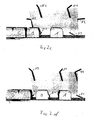
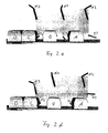
- FIG. 2 is shown in the individual diagrams 2a to 2g of the particularly advantageous movement of the present invention.
- it has been dispensed with individually to depict the articles to be packaged, for example bottles in the present exemplary embodiment. Instead, only the enveloping body of the divided or subsequently still be divided article groups (eg Fig. 2a , Pos B and C, or Fig. 2d , Pos C and D).
- FIG. 2 was dispensed with an explicit representation of the three drive elements 1, it was shown in a schematic diagram, only the trajectory 4 of the drive elements 1.
- the attached to the three drive elements 1 cross bars 2 were marked according to their affiliation to a drive elements 1.
- the cross bars 2 with the marking K2 are fastened to the second drive element 1, the transverse bars 2 with the marking K3 correspondingly to the third drive element 1.
- the articles to be separated and synchronized are fed to the compartment, synchronization and compacting device by an infeed conveyor 5, the articles being permanently held under dynamic pressure by continuously conveying the infeed conveyor 5 within the compartment unit and thus striving to move in the conveying direction.
- the articles are first fed by the infeed conveyor 5 onto a fixed, non-moving component, e.g. a sheet 8 or similar, postponed.
- a push-on wedge 7 which performs a controlled movement. This sequence of movements consists of a forward and backward movement, each with different, not necessarily constant speeds and possibly, additional defined standstill phases together.
- the main conveyor 6 connects.
- This main conveyor 6 is operated at a constant speed which is greater than that of the inlet conveyor 5.
- the subsequent stream of articles is held by the inlet conveyor 5 under dynamic pressure, so that the subsequently divested article groups B and C initially connect to each other gapless.
- the pusher wedge 7 assumes an important function. During the forward movement of the tapering article flow of the pusher wedge 7 also extends and carries during this forward movement, the article group B to be split, thereby preventing this group of articles comes into contact with the main conveyor 6.
- the length of the article group to be split is greater than the effective length of the slip wedge 7, so is already a part of the article group on the main conveyor 6, so prevents the moving with the speed of the inlet conveyor 5 transverse bar K1 gap formation within this group of items.
- the push-on wedge 7 effects a backward movement, whereby the entire article group B to be separated is placed on the main conveyor 6 and thus assumes the higher speed of the main conveyor 6. Since also the cross bar K1 assumes the higher speed of the main conveyor 6 at this time, the desired gap formation occurs for the following article group C.
- the backward movement of the pusher wedge 7 ends at the front edge of the subsequently classified article group C. If this front edge is reached, then the pusher wedge 7 follows the forward movement of the article group C, where it executes them at the same speed as the article group C (see Fig. 2b ).
- the next transverse bar 2, here K2 plunges into the resulting gap and prevents premature gap formation within the following article group C, with the transverse bar K2 moving essentially in line with the speed of the inlet conveyor 5 after being immersed in the gap ,
- the pusher wedge 7 continues to move out, wherein it continues to maintain contact with the front edge of the article group C and prevents this article group from coming into contact with the main conveyor 6.
- the cross bar K1 is moved as long with a relation to the main conveyor 6 increased speed until the cross bar reaches the back of the previous article group A.
- the transverse rod K1 again assumes the speed of the main conveyor 6 and pushes the article group A through the compression unit, not shown.
- compaction units are state of the art and usually consist of guide plates arranged on both sides of the path of the article group, which form a funnel-shaped bottleneck, whereby gaps existing within the transverse rows of the article group are closed. Gaps present within the longitudinal rows are created by sliding the article group onto a fixed component, e.g. a sheet, closed, the cross bar K1 causes the forward movement of the article group by pushing.
- a fixed component e.g. a sheet
- compartment, synchronization and compression station are realized in only one module, resulting from the highly advantageous embodiment of the present invention further advantages.
Landscapes
- Engineering & Computer Science (AREA)
- Mechanical Engineering (AREA)
- Attitude Control For Articles On Conveyors (AREA)
- Auxiliary Devices For And Details Of Packaging Control (AREA)
- Specific Conveyance Elements (AREA)
Description
Die vorliegende Erfindung betrifft eine Vorrichtung zum Abteilen, Synchronisieren und Verdichten von Artikeln gemäß dem Oberbegriff des Anspruchs 1.The present invention relates to a device for dividing, synchronizing and compacting articles according to the preamble of
Vorrichtungen dieser Art werden innerhalb von Verpackungsmaschinen benötigt, um aus in geschlossenen Reihen zulaufenden Artikelströmen einzelne Artikelgruppen oder Artikel zu bilden bzw. abzutrennen, welche nachfolgend in Kartons, Kästen, Trays und/oder Schrumpffolie verpackt werden.Devices of this type are required within packaging machines to form individual article groups or articles from article streams flowing in closed rows, which are subsequently packaged in cartons, boxes, trays and / or shrink film.
Dieser Verpackungsprozess besteht aus mehreren Teilprozessen, wobei es Stand der Technik ist, für die Durchführung dieser Teilprozesse jeweils einzelne Maschinen, zumindest aber einzelne, abgeschlossene Baugruppen oder Module einzusetzen.This packaging process consists of several sub-processes, whereby it is state of the art to use individual machines for the implementation of these sub-processes, but at least individual, closed assemblies or modules.
Zunächst wird der Artikelstrom, wobei es sich um Behälter oder Güter aller Art wie z.B. Flaschen, Tüten, Dosen, Kartons, Beutelverpackungen usw. handeln kann, durch einen Transporteur der Abteilvorrichtung zugeführt.Initially, the article stream, which will be containers or goods of all kinds, e.g. Bottles, bags, cans, cartons, pouches, etc. can be supplied through a feed dog of the compartment device.
Bei diesem Transporteur handelt es sich in der Regel um eine, mit einem breiten Transportband ausgestattete Vorrichtung, welche zusätzlich mit aus Blech bestehenden Führungen ausgestattet ist, wobei diese über dem Transportband angeordnete Gassen bilden.In this conveyor is usually a, equipped with a wide conveyor belt device, which is additionally equipped with guides made of sheet metal, which form over the conveyor belt arranged lanes.
Diese Gassen wiederum unterteilen den zunächst ungeordnet einlaufenden Artikelstrom in sogenannte Reihen.These lanes in turn subdivide the initially unordered incoming stream of articles into so-called rows.
Durch eine geeignete Abteilvorrichtung wird von diesem, in den einzelnen Gassen auf Stoß stehenden Artikelstrom die gewünschte Artikelmenge abgeteilt, wobei sich die Artikelmenge durch die Multiplikation der Anzahl der Reihen in Laufrichtung mit der Anzahl der Reihen quer zur Laufrichtung ergibt. Die abgeteilten Reihen in Laufrichtung ergeben in Verbindung mit den Reihen quer zur Laufrichtung das so genannte Format welches anschließend verpackt werden soll.By means of a suitable dividing device, the desired quantity of articles is divided by the article stream standing in abutment in the individual lanes, the quantity of articles resulting from the multiplication of the number of rows in the running direction by the number of rows transversely to the running direction. The divided rows in the direction of travel, in conjunction with the rows transverse to the direction of the so-called format which is then to be packaged.
Um die nachfolgende Verpackung des erzeugten Formats überhaupt zu ermöglichen, ist es erforderlich, zwischen erzeugtem Format und nachfolgendem Artikelstrom eine Lücke zu erzeugen. Dieses geschieht in der Regel dadurch, dass der Artikelstrom mit unveränderter Geschwindigkeit fortbewegt wird, während das erzeugte Format mit erhöhter Geschwindigkeit weitertransportiert wird.In order to enable the subsequent packaging of the produced format at all, it is necessary to create a gap between the generated format and the following article stream. This is usually done by moving the stream of articles at unvaried speed while advancing the generated format at an increased rate.
Den nächsten Prozessschritt stellt die so genannte Verdichtung dar, welche dazu dient, die innerhalb des Formats durch die Führungen und eventuelle Verschiebungen der Artikel untereinander entstandene Lücken zu schließen. Hierzu wird das Format anhand einer geeigneten Vorrichtung durch sich verengende Außenführungen bewegt, wodurch die durch die Führungen erzeugten Lücken geschlossen werden. Gleichzeitig oder aber auch anschließend wird das Format vom Transporteur ab- und auf ein feststehendes Blech aufgeschoben, was zur Folge hat, dass die innerhalb der Reihen in Laufrichtung vorhandenen Lücken ebenfalls geschlossen werden.The next process step is the so-called compaction, which serves to close the gaps created within the format by the guides and possible displacements of the articles. For this purpose, the format is moved by means of a suitable device by narrowing outer guides, whereby the gaps generated by the guides are closed. At the same time or else subsequently, the format is removed from the feed dog and pushed onto a stationary sheet, with the result that the gaps in the running direction within the rows are likewise closed.
Eine weitere wichtige Funktion welche während des Verdichtens durchgeführt wird ist die teilungsgerechte Positionierung oder aber auch Synchronisation des Formats mit dem Maschinentakt. Dieses ist erforderlich, da es bedingt durch das Auf-, Ab- und Überschieben der Artikel bzw. des Formats von oder nach bewegten oder feststehenden Vorrichtungskomponenten, immer wieder zu räumlichen Verschiebungen kommen kann, welche zur Folge haben, dass sich das Format nicht an der Stelle befindet, an der es gemäß des geplanten Bewegungsablaufes sein müsste.Another important function which is carried out during compaction is the division-oriented positioning or else synchronization of the format with the machine cycle. This is necessary because it can cause due to the up, down and sliding over the article or the format of or after moving or fixed device components, again and again to spatial shifts, which have the consequence that the format is not at the Location is where it should be according to the planned movement.
Anschließend erfolgt die Verpackung des so verdichteten Formats.Subsequently, the packaging of the so compacted format.
Zur Realisierung der oben beschriebenen Abläufe sind in der Vergangenheit zahlreiche Vorschläge unterbreitet worden, wobei allen bekannten Vorschlägen gemeinsam ist, dass zumindest für die Funktionen Abteilen und Verdichten/Synchronisieren eigene, abgeschlossene Baugruppen bzw. Module verwendet werden, was einen hohen konstruktiven und fertigungstechnischen Aufwand und damit verbunden auch entsprechend hohe Kosten bedeutet.To implement the processes described above, numerous proposals have been made in the past, with all known proposals in common is that at least for the functions compartments and compaction / synchronization own, completed modules or modules are used, resulting in a high design and manufacturing effort and associated with it also means correspondingly high costs.
Ebenfalls haben Vorrichtungen welche dem Stand der Technik entsprechen, aufgrund der zahlreichen Module aus denen sie bestehen, einen großen Platzbedarf.Also have devices which correspond to the prior art, due to the numerous modules that make them, a large amount of space.
Eine entsprechende Vorrichtung wurde z.B. mit der
Bei dieser Vorrichtung werden einzelne Artikelreihen des Artikelstromes zunächst durch von unten in den Artikelstrom eintauchende, fingerförmige Elemente abgeteilt und weitertransportiert. Anschließend senkt sich die Synchronisationsvorrichtung von oben zwischen die abgeteilten Artikelreihen und beginnt diese zu schieben und somit zu synchronisieren.An appropriate device was eg with the
In this device, individual product lines of the article flow are first divided by submerged from below into the article flow, finger-shaped elements and transported. Subsequently, the synchronization device lowers between the top of the divided article rows and starts to push them and thus to synchronize.
Dabei besteht diese Synchronisationsvorrichtung aus beidseitig des Behälterstromes angeordneten, parallel verlaufenden, synchron angetriebenen Ketten, wobei an diesen Ketten mehrere Stäbe derart angeordnet sind, dass diese Stäbe quer zur Transportrichtung verlaufen und somit durch ihre Vorwärtsbewegung die Artikel mitnehmen und synchronisieren.In this case, this synchronization device consists of both sides of the container stream arranged, parallel, synchronously driven chains, wherein these rods are arranged a plurality of bars such that these bars extend transversely to the transport direction and thus take along the articles by their forward movement and synchronize.
Als Besonderheit ist bei dieser Vorrichtung zu bemerken, dass zu Beginn der Synchronisation zwei Kettenpaare ineinander greifen, wodurch zunächst jede einzelne Artikelreihe durch einen eigenen Querstab transportiert wird. Nach einer bestimmten Wegstrecke wird eines der beiden Kettenpaare aus dem Artikelstrom herausgeführt, so dass im weiteren Verlauf der Wegstrecke nur noch das verbliebene Kettenpaar die nachfolgende Verdichtung und Synchronisation durchführt, was auch zur Folge hat, dass mehrere Querreihen (Artikelreihen quer zur Laufrichtung) von einem Querstab transportiert werden, wodurch schließlich das eigentliche Format gebildet wird.A special feature of this device is to note that at the beginning of the synchronization two pairs of chains interlock, whereby initially each individual article row is transported by its own cross bar. After a certain distance one of the two pairs of chains is led out of the flow of articles, so that in the further course of the route only the remaining pair of chains performs the subsequent compression and synchronization, which also has the consequence that several transverse rows (rows of articles transverse to the direction) of a Cross bar are transported, whereby finally the actual format is formed.
Nachteilig an einer derartigen Vorrichtung ist, dass eine Änderung des erzeugten Formates nur durch die Montage bzw. Demontage von zahlreichen Querstäben möglich ist. Darüber hinaus lassen sich durch das Ineinandergreifen der beiden Kettenpaare und die weiteren konstruktiven Merkmale der Vorrichtung nicht alle gewünschten Formate erzeugen.A disadvantage of such a device is that a change of the generated format only by the assembly or disassembly of numerous crossbars is possible. In addition, not all desired formats can be generated by the intermeshing of the two pairs of chains and the other structural features of the device.
Ebenfalls wurde eine Vorrichtung nach der
Synchronisation und Verdichtung erfolgen durch ein oberhalb der Transportebene angeordnetes Kettenpaar, welches ebenfalls mit Querstäben versehen ist.
Auch bei dieser Vorrichtung ist es von großem Nachteil, dass Änderungen des Formats nur durch umfangreiche Umbauten, insbesondere der Abteileinheit, wo neben einem Wechsel der verwendeten Ketten auch ein Versetzen der entsprechenden Kettenumlenkrolle erforderlich ist, erreicht werden können.Also, a device according to the
Synchronization and compression take place by means of a chain pair arranged above the transport plane, which is likewise provided with transverse bars.
Also in this device, it is a great disadvantage that changes in format only by extensive conversions, in particular the Abteileinheit, where in addition to a change in the chains used also a displacement of the corresponding Kettenumlenkrolle required can be achieved.
Ebenfalls bekannt wurde eine Vorrichtung nach der
Auf jeder Führungsbahn befindet sich ein so genannter Linearschlitten, welcher mit ein- und ausfahrbaren Rückhaltehebeln versehen ist.On each guideway is a so-called linear slide, which is provided with retractable and retractable retaining levers.
Alle Linearschlitten werden über je eine mit ihnen verbundene Antriebskette angetrieben, wobei alle Linearschlitten eines Satzes bzw. einer Höhenebene durch einen gemeinsamen Servomotor angetrieben und synchron bewegt werden.All linear slides are each driven by a drive chain connected to them, wherein all linear slides of a set or a height level are driven by a common servomotor and moved synchronously.
Dadurch, dass die Linearschlitten der verschiedenen Sätze auf unterschiedlichen Höhenebenen angeordnet sind, können sie völlig unabhängig voneinander vor und zurück bewegt werden.The fact that the linear slide of different sets are arranged at different levels, they can be moved back and forth completely independently.
Die Abteilung der Artikelgruppen erfolgt dadurch, dass ein erster Satz Linearschlitten mit ausgefahrenen Rückhaltehebeln eine Vorwärtsbewegung ausführt und dabei den nachdrängenden Artikelstrom gegenüber dem mit höherer Geschwindigkeit laufenden Transportband zurückhält. Zeitgleich führt ein zweiter Satz Linearschlitten mit eingefahrenen Rückhaltehebeln eine Rückwärtsbewegung aus.The department of article groups is made by a first set of linear slide with extended retaining levers makes a forward movement, while retaining the nachdrängenden article flow against the higher-speed conveyor belt. At the same time, a second set of linear slides with retracted retaining levers makes a backward movement.
Hat dieser zweite Satz Linearschlitten den Endpunkt der Rückwärtsbewegung erreicht, so werden die Rückhaltehebel ausgefahren wodurch eine Artikelgruppe vom Artikelstrom abgeteilt wird. Sind die Rückhaltehebel ausgefahren, so gibt der erste Satz Linearschlitten durch das Einfahren seiner Rückhaltehebel die Vorderkante der soeben gebildeten Artikelgruppe frei, welche alsdann mit der höheren Transportbandgeschwindigkeit weitertransportiert wird und somit gleichzeitig eine Lücke zum nachfolgenden, aber vom zweiten Satz der Linearschlitten zurückgehaltenen Artikelstrom ausbilden kann.If this second set of linear slides has reached the end point of the backward movement, the retaining levers are extended, whereby an article group is separated from the article flow. If the retaining levers are extended, the first set of linear slides releases the leading edge of the just-formed article group, which is then transported further at the higher conveyor belt speed and thus can simultaneously form a gap to the following article stream retained by the second set of linear slides ,
Die anschließende Verdichtung/Synchronisation der Artikelgruppe erfolgt in einer eigenen Vorrichtung auf bekannte Weise.The subsequent compaction / synchronization of the article group takes place in a separate device in a known manner.
Nachteilig an einer derartigen Vorrichtung ist, dass der in den meisten Fällen bereits eng zusammenstehende Artikelstrom zunächst auseinander geführt werden muss, da die Linearschlitten u.a. zwischen den einzelnen Längsreihen angeordnet sind.
Weitere Schwierigkeiten ergeben sich aufgrund dieser Anordnung dadurch, dass im Rahmen der Verdichtung sehr große Lücken abgebaut werden müssen, was insbesondere bei kippempfindlichen Artikeln zu häufigem Umfallen selbiger führt, was in der Praxis äußerst unerwünscht ist.A disadvantage of such a device is that the article stream, which in most cases is already close together, must first be separated, since the linear carriages are inter alia arranged between the individual longitudinal rows.
Further difficulties arise due to this arrangement in that in the context of compression very large gaps must be reduced, which leads selbiger in particular with tilt-sensitive articles to frequent overturning, which is extremely undesirable in practice.
Des weiteren bereitet die Verarbeitung von Artikeln mit einer quadratischen Querschnittsfläche große Schwierigkeiten, da sich eine geschlossene Außenfläche ausbildet wenn mehrere derartige Artikel auf Stoß hintereinander stehen, wodurch kein geeigneter Eingriffspunkt für die Rückhaltehebel vorhanden ist.Furthermore, the processing of articles with a square cross-sectional area creates great difficulties, since a closed outer surface is formed when several such articles are in abutment with each other, whereby no suitable point of engagement for the retaining levers is present.
Ebenfalls ist der große mechanische und monetäre Aufwand einer solchen Vorrichtung eindeutig als Nachteil anzusehen.Also, the great mechanical and monetary expense of such a device is clearly to be regarded as a disadvantage.
Aufgabe und Ziel der vorliegenden Erfindung ist es, die oben dargestellten Nachteile zu vermeiden und eine Vorrichtung zu schaffen, welche es gestattet, die erforderlichen Kosten, die Anzahl der Bauteile und den Raumbedarf deutlich zu reduzieren. Dazu ist vorgesehen, die Abteileinheit und die Verdichtungs-/Synchronisationseinheit zu einer Einheit zusammen zu fassen. Gelöst wird diese Aufgabe durch die kennzeichnenden Merkmale des Anspruchs 1.The object and purpose of the present invention is to obviate the drawbacks presented above and to provide a device which makes it possible to significantly reduce the required costs, the number of components and the space requirement. For this purpose, it is provided that the compartment unit and the compression / synchronization unit to form a unit together. This problem is solved by the characterizing features of
Im Nachfolgenden wird die vorliegende Erfindung anhand von Ausführungsbeispielen näher erläutert.In the following, the present invention will be explained in more detail by means of exemplary embodiments.
Im Einzelnen zeigt die
- Figur 1:
- in einer vereinfachten, perspektivischen Darstellung eine erfindungsgemäße Vorrichtung und die
- Figur 2a bis 2g
- in einer ebenfalls vereinfachten Darstellung einen erfindungsgemäßen Bewegungsablauf.
- FIG. 1:
- in a simplified, perspective view of an inventive device and the
- FIGS. 2a to 2g
- in a likewise simplified representation of a movement sequence according to the invention.
Weiterbildungen, Vorteile und Anwendungsmöglichkeiten der Erfindung ergeben sich aus der nachfolgenden Beschreibung von Ausführungsbeispielen und der Zeichnung. Gleichzeitig wird der Inhalt der Ansprüche zu einem Bestandteil der Beschreibung gemacht.Further developments, advantages and applications of the invention will become apparent from the following description of exemplary embodiments and the drawings. At the same time, the content of the claims becomes part of the description made.
Für eine erfindungsgemäße Abteil- und Synchronisierungsstation ist mindestens ein Paar Antriebselemente 1 vorgesehen, an welchem mindestens ein Querstab 2 angeordnet ist.For a compartment and synchronization station according to the invention, at least one pair of
Bei diesen Antriebselementen kann es sich z.B. um aus Metall oder auch einem anderen geeigneten Werkstoff gefertigte Ketten, insbesondere auch um so genannte Rollengliederketten handeln. Ebenfalls ist auch die Verwendung von Zahnriemen vorgesehen, wobei insbesondere solche Zahnriemen vorgesehen sind, an welchen mittels geeigneter Elemente der oben erwähnte Querstab 2 befestigt werden kann.These drive elements may be e.g. to chains made of metal or other suitable material, in particular to act so-called roller link chains. Also, the use of toothed belt is provided, in particular such toothed belts are provided, which can be fixed by means of suitable elements of the above-mentioned
Unter einem Paar Antriebselemente 1 sind in diesem Zusammenhang die Antriebselemente zu verstehen, welche von einem gemeinsamen Antriebsmotor angetrieben werden und wobei sich eines dieser Antriebselemente 1 links und eine Antriebselement 1 rechts vom Weg der abzuteilenden bzw. bereits abgeteilten Artikelgruppen befindet.In this context, a pair of
Im, in der
Die Realisierung von Varianten mit Anzahlen von Paaren Antriebselementen 1 und Anzahlen von Querstäben 2, welche vom dargestellten Ausführungsbeispiel abweichen, führen nicht dazu, dass der Umfang der vorliegenden Anmeldung verlassen wird.The realization of variants with numbers of pairs of
Jedes der Paare Antriebselemente 1 wird durch einen eigenen Motor 3 angetrieben, wobei es sich bei diesem Motor z.B. um einen elektrisch betriebenen Schritt-, Servo- oder Synchronmotor handeln kann. Dabei ist allen Motorarten gemeinsam, dass Drehwinkel, Drehrichtung und Drehgeschwindigkeit durch einen Rechner oder eine andere geeignete Steuervorrichtung vorgegeben werden und dass die Einhaltung dieser Soll-Werte durch geeignete Überwachungsvorrichtungen wie z.B. Drehgebern überwacht und zur nachfolgenden Auswertung weitergemeldet werden.Each of the pairs of
Zusätzlich ist für die Ansteuerung bzw. den Betrieb dieser Motoren vorgesehen, dass Drehgeschwindigkeit und/oder Drehrichtung des Motors und somit auch Bewegungsgeschwindigkeit und/oder Bewegungsrichtung der von diesem Motor angetriebenen Paares Antriebselemente 1 auch innerhalb eines bzw. eines halben Umlaufs der Antriebselemente 1 an verschiedene Soll-Werte angepasst werden können. Dabei ist ebenfalls vorgesehen, dass die Bewegungsgeschwindigkeit der Antriebselemente 1 auch den Wert Null m/s erreichen kann, wobei dieser Wert der Geschwindigkeit nicht nur während eines eventuellen Wechsels der Bewegungsrichtung zwangsweise erreicht wird, sondern auch gezielt für ein bestimmtes Zeitintervall vorgegeben werden kann.In addition, it is provided for the activation or the operation of these motors that the rotational speed and / or direction of rotation of the motor and thus also movement speed and / or direction of movement of the motor driven by this pair of
Die Länge eines Arbeitszyklusses wird von der Anzahl der an einem Paar Antriebselemente 1 montierten Querstäbe 2 bestimmt. Ist jeweils nur ein Querstab 2 montiert, so entspricht ein Arbeitszyklus einem Umlauf der Antriebselemente 1. Sind hingegen zwei Querstäbe 2 montiert, so entspricht ein Arbeitszyklus einem halben Umlauf der Antriebselemente 1.The length of a working cycle is determined by the number of
Im dargestellten Ausführungsbeispiel erfolgte die konstruktive Auslegung derart, dass sich die einzelnen Antriebselemente 1, aufgrund der auf einer gemeinsamen Höhenebene angeordneten Querstäbe 2, nicht gegenseitig überholen können. In einer weiteren Ausgestaltung der vorliegenden Erfindung ist vorgesehen, Antriebselemente 1 und/oder Querstäbe 2 derart anzuordnen, dass diese sich gegenseitig überholen können.In the illustrated embodiment, the structural design was made such that the
In der
Innerhalb der
Die abzuteilenden und zu synchronisierenden Artikel werden der Abteil-, Synchronisierungs- und Verdichtungsvorrichtung durch einen Einlaufförderer 5 zugeführt, wobei die Artikel durch kontinuierliches Fördern des Einlaufförderers 5 innerhalb der Abteileinheit permanent unter Staudruck gehalten werden und somit das Bestreben haben sich in Förderrichtung zu bewegen.The articles to be separated and synchronized are fed to the compartment, synchronization and compacting device by an
Innerhalb der Vorrichtung werden die Artikel durch den Einlaufförderer 5 zunächst auf eine feststehende, nicht bewegliche Komponente, z.B. ein Blech 8 o.ä., aufgeschoben. Unterhalb dieses Bleches befindet sich ein Aufschubkeil 7, welcher einen gesteuerten Bewegungsablauf ausführt. Dieser Bewegungsablauf setzt sich aus einer Vor- und Rückbewegung mit jeweils unterschiedlichen, nicht zwingend konstanten Geschwindigkeiten und eventuellen, zusätzlichen definierten Stillstandsphasen zusammen.Within the device, the articles are first fed by the
An das Blech 8 bzw. den Aufschubkeil 7 schließt sich der Hauptförderer 6 an. Dieser Hauptförderer 6 wird mit einer konstanten Geschwindigkeit betrieben, welche größer ist als die des Einlaufförderers 5.To the sheet 8 and the postponement wedge 7, the
Nachfolgend werden die wesentlichen Bestandteile des Bewegungsablaufes einer erfindungsgemäßen Vorrichtung beispielhaft, aber den Umfang der vorliegenden Erfindung nicht beschränkend, dargestellt. Abweichungen vom dargestellten Bewegungsablauf, der Verzicht auf oder das Hinzufügen von Bewegungsabschnitten und/oder verwendeten Komponenten führt nicht dazu, dass der Schutzbereich der vorliegenden Erfindung verlassen wird.In the following, the essential components of the movement sequence of a device according to the invention will be described by way of example, but not limiting the scope of the present invention. Deviations from the illustrated sequence of movements, the Omission or addition of motion sections and / or components used will not result in abandoning the scope of the present invention.
Wie in der
Der Kontakt der abzuteilenden Artikelgruppe B mit dem Hauptförderer 6 muss zunächst verhindert werden, da der Hauptförderer 6 mit einer höheren Bandgeschwindigkeit als der Einlaufförderer 5 betrieben wird und ein vorzeitiger Kontakt aufgrund der Geschwindigkeitsdifferenz eine vorzeitige und somit unerwünschte Lückenbildung innerhalb der abzuteilenden Artikelgruppe zur Folge hätte.The contact of the article group B to be separated with the
Ist die Länge der abzuteilenden Artikelgruppe größer als die wirksame Länge des Aufschubkeils 7, steht also schon ein Teil der Artikelgruppe auf dem Hauptförderer 6, so verhindert der sich mit der Geschwindigkeit des Einlaufförderers 5 bewegende Querstab K1 eine Lückenbildung innerhalb dieser Artikelgruppe.If the length of the article group to be split is greater than the effective length of the slip wedge 7, so is already a part of the article group on the
Befindet sich die abzuteilende Artikelgruppe B weit genug über oder auf dem Hauptförderer 6, so führt der Aufschubkeil 7 eine Rückwärtsbewegung aus, wodurch die gesamte abzuteilende Artikelgruppe B auf dem Hauptförderer 6 abgestellt wird und somit die höhere Geschwindigkeit des Hauptförderers 6 annimmt. Da auch der Querstab K1 zu diesem Zeitpunkt die höhere Geschwindigkeit des Hauptförderers 6 annimmt, kommt es zur gewünschten Lückenbildung zur nachfolgenden Artikelgruppe C.
Die Rückwärtsbewegung des Aufschubkeils 7 endet an der Vorderkante der nachfolgend abzuteilenden Artikelgruppe C. Ist diese Vorderkante erreicht, so folgt der Aufschubkeil 7 wiederum der Vorwärtsbewegung der Artikelgruppe C, wobei er diese mit der selben Geschwindigkeit wie die Artikelgruppe C ausführt (siehe
The backward movement of the pusher wedge 7 ends at the front edge of the subsequently classified article group C. If this front edge is reached, then the pusher wedge 7 follows the forward movement of the article group C, where it executes them at the same speed as the article group C (see
Ist die Lücke zwischen der Artikelgruppe B und C groß genug (siehe
Wurde die vorhergehende Artikelgruppe B durch den Hauptförderer eine bestimmte Wegstrecke transportiert, so wird die Geschwindigkeit des zugeordneten Querstabes K1 erhöht, wodurch sich dieser von der Artikelgruppe B entfernt.If the preceding article group B was transported by the main conveyor a certain distance, the speed of the associated transverse bar K1 is increased, whereby it moves away from the article group B.
Wie in den
Diese Verdichtungseinheiten gehören zum Stand der Technik und bestehen üblicher Weise aus beidseitig des Weges der Artikelgruppe angeordneten Führungsblechen welche einen trichterförmigen Engpass bilden, wodurch innerhalb der Querreihen der Artikelgruppe vorhandene Lücken geschlossen werden. Innerhalb der Längsreihen vorhandene Lücken werden durch das Aufschieben der Artikelgruppe auf eine feststehende Komponente, z.B. einem Blech, geschlossen, wobei der Querstab K1 durch Schieben die Vorwärtsbewegung der Artikelgruppe bewirkt.These compaction units are state of the art and usually consist of guide plates arranged on both sides of the path of the article group, which form a funnel-shaped bottleneck, whereby gaps existing within the transverse rows of the article group are closed. Gaps present within the longitudinal rows are created by sliding the article group onto a fixed component, e.g. a sheet, closed, the cross bar K1 causes the forward movement of the article group by pushing.
Hat der Querstab K1 die Artikelgruppe anschließend wieder von der feststehenden Komponente abgeschoben, so sind alle innerhalb der Artikelgruppe vorhandenen Lücken geschlossen und die Artikelgruppe ist genau positioniert und mit dem Maschinentakt synchronisiert. Anschließend wird der Querstab aus der Ebene der Artikelgruppen herausgeführt.If the crossbar K1 has subsequently pushed the article group away from the fixed component, then all gaps existing within the article group are closed and the article group is precisely positioned and synchronized with the machine cycle. Subsequently, the cross bar is led out of the level of the article groups.
Neben des bereits oben beschriebenen Vorteils, dass Abteil-, Synchronisierungs- und Verdichtungsstation in nur einem Modul realisiert werden, ergeben sich durch die überaus vorteilhafte Ausgestaltung der vorliegenden Erfindung weitere Vorteile.In addition to the already described above advantage that compartment, synchronization and compression station are realized in only one module, resulting from the highly advantageous embodiment of the present invention further advantages.
So ist z.B. die Veränderung der zu erzeugenden Formate insbesondere bei konstanter Anzahl der Querreihen auf einfache Art und Weise möglich, da zur Veränderung der Anzahl der Längsreihen lediglich eine Anpassung der programmierten Bewegungsabläufe von Antriebsketten 1 und Aufschubkeil 7 erforderlich ist, was quasi per "Knopfdruck" und ohne mechanische Umstellungen an der Verpackungsmaschine selbst erfolgen kann.For example, e.g. the change of the formats to be produced in a simple manner possible, in particular with a constant number of transverse rows, since to change the number of longitudinal rows only an adjustment of the programmed movements of
Zur Realisierung dieser Funktion ist vorgesehen, die erforderlichen Bewegungsprofile von Antriebselementen 1 und Aufschubkeil 7 und sonstige Steuerungsparameter, wie z.B. Geschwindigkeiten der Förderer 5,6, für jedes gewünschte Format und/oder jeden zu verarbeitenden Artikel in der Maschinensteuerung derart zu speichern, dass relevanten Daten leicht vom Bedienungspersonal abgerufen werden können.To realize this function, it is provided that the required movement profiles of
Besonderen Nutzen entfalten die Vorteile der vorliegenden Erfindung bei an sich unveränderten Formaten, insbesondere auch bei häufigen Artikelwechseln, da verschiedene Artikel in der Regel auch unterschiedliche Abmessungen aufweisen, was bei bekannten Verpackungsvorrichtungen aufwändige und zeitraubende Einstellarbeiten erforderlich macht, welche bei einer erfindungsgemäßen Vorrichtung nahezu vollständig entfallen.The advantages of the present invention are of particular benefit in the case of formats which are generally unchanged, in particular also with frequent article changes, since different articles as a rule also have different dimensions, which is complicated and time-consuming in the case of known packaging devices Adjustments required, which accounts for almost completely in a device according to the invention.
Durch die Zusammenfassung der Funktionen Abteilung, Synchronisation und Verdichtung zu einem Modul lässt sich eine bedeutende Reduzierung der erforderlichen Maschinenlänge erreichen, was aufgrund der nicht unerheblichen Raumkosten eine weitere beträchtliche Kosteneinsparung ermöglicht.By combining the functions of department, synchronization and compaction into one module, a significant reduction in the required machine length can be achieved, which, due to the not inconsiderable space costs, allows a further considerable cost saving.
Durch die überaus vorteilhafte Gestaltung der vorliegenden Erfindung ergibt sich noch ein weiterer bedeutender Vorteil.
Da es bei einer erfindungsgemäßen Vorrichtung nicht erforderlich ist, Bauteile innerhalb des Weges der abgeteilten Artikelgruppen anzuordnen, ergibt sich die Möglichkeit, zumindest den Hauptförderer 6 als ein einteiliges, eine geschlossene Oberfläche aufweisendes, breites Transportband auszubilden. Durch diese Vorgehensweise ergibt sich gegenüber dem Stand der Technik, bei dem es üblich ist, den Hauptförderer 6 aus mehreren, parallel laufenden, schmalen Transportbändern zu bilden, der Vorteil, dass keine Störungen der Oberfläche vorhanden sind, welche während des Transportes oder aber auch insbesondere während der Verdichtung die Ursache für das Umfallen der Artikel sein können.Due to the extremely advantageous design of the present invention, yet another significant advantage.
Since it is not necessary in a device according to the invention to arrange components within the path of the divided article groups, there is the possibility of forming at least the
Claims (17)
- Apparatus for separating, synchronising and compacting for the packing of objects of all kinds, said apparatus having at least one inlet conveyor (5), at least one hold-back wedge (7), at least one main conveyor (6) and at least one compacting unit, wherein the speed of the main conveyor (5) is greater than that of the inlet conveyor, the said apparatus having at least one pair of driving elements (1) disposed so as to rotate, at least one crossbar (2) that is disposed at each pair of driving elements (1) and a controlled drive motor (3) for each pair of driving elements (1), characterised in that the at least one pair of driving elements (1) has a controlled sequence of movement that includes different speeds, wherein the structural development of the apparatus is such that the separating is carried out by the hold-back wedge (7) that is displaceable forward and backward and the synchronising and compacting of the objects is carried out by the at least one pair of driving elements (1), and wherein the speed of the main conveyor (6) is constant.
- Apparatus according to claim 1, characterised in that the structural development of the apparatus is such that the crossbars (2) that are disposed on different pairs of driving elements (1) cannot pass one another.
- Apparatus according to one of claim 1 or 2, characterised in that the structural development of the apparatus is such that the crossbars (2) that are disposed on different pairs of driving elements (1) can pass one another.
- Apparatus according to one of claims 1 to 3, characterised in that the at least one pair of driving elements (1) are chains.
- Apparatus according to one of claims 1 to 3, characterised in that the at least one pair of driving elements (1) are toothed belts.
- Apparatus according to one of claims 1 to 5, characterised in that the apparatus includes means, which make it possible for the hold-back wedge (7) to perform the forward and backward movements at different, controlled speeds.
- Apparatus according to one of claims 1 to 6, characterised in that both the inlet conveyor (5) and the main conveyor (6) are each provided with their own drive motor.
- Apparatus according to one of claims 1 to 7, characterised in that the main conveyor (6) is in the form of a one-part, wide conveyor belt that includes a substantially closed surface.
- Method for the operation of an apparatus in accordance with one of claims 1 to 8, characterised in that the sequence of movement of the at least one pair of driving elements (1) and/or the at least one crossbar (2) includes different speeds during one operating cycle.
- Method according to claim 9, characterised in that the at least one crossbar (2) initially holds back the group of objects that is to be separated in relation to the main conveyor (6), then is moved forward at a greater speed, once it reaches the previously separated group of objects synchronizes the said group of objects with the operating cycle of the apparatus and then pushes this group of objects through a compacting unit.
- Method according to claim 10, characterised in that the at least one crossbar (2), once it has separated one group of objects, is initially moved at a speed similar to that of the main conveyor (6), is then advanced at a higher speed, and is then moved once again at a speed similar to that of the main conveyor (6).
- Method according to one of claim 9 to 11, characterised in that the adjusting of the apparatus to changed formats and/or changed article dimensions with an unchanged number of transverse rows is effected exclusively by means of changing the control parameters within the control program, and/or the control of the apparatus.
- Method according to claim 12, characterised in that the relevant control parameters per format and/or object dimension are stored and can be called up as required.
- Method according one of claims 9 to 13, characterised in that the hold-back wedge (7) executes a forward movement and a backward movement.
- Method according to claim 14, characterised in that the hold-back wedge (7) executes the forward movement at a first speed and the backward movement at a second speed.
- Method according to claim 15, characterised in the first speed and the second speed are identical.
- Method according to one of claims 9 to 16, characterised in that the inlet conveyor (5) and the main conveyor (6) are each driven at their own speeds which are independent of each other.
Priority Applications (1)
| Application Number | Priority Date | Filing Date | Title |
|---|---|---|---|
| PL04018531T PL1522508T5 (en) | 2003-10-09 | 2004-08-05 | Separating, synchronising and accumulating device |
Applications Claiming Priority (2)
| Application Number | Priority Date | Filing Date | Title |
|---|---|---|---|
| DE10347540A DE10347540B4 (en) | 2003-10-09 | 2003-10-09 | Compartment, synchronization and compression device |
| DE10347540 | 2003-10-09 |
Publications (3)
| Publication Number | Publication Date |
|---|---|
| EP1522508A1 EP1522508A1 (en) | 2005-04-13 |
| EP1522508B1 EP1522508B1 (en) | 2007-01-17 |
| EP1522508B2 true EP1522508B2 (en) | 2009-11-11 |
Family
ID=34306386
Family Applications (1)
| Application Number | Title | Priority Date | Filing Date |
|---|---|---|---|
| EP04018531A Expired - Lifetime EP1522508B2 (en) | 2003-10-09 | 2004-08-05 | Separating, synchronising and accumulating device |
Country Status (7)
| Country | Link |
|---|---|
| US (2) | US20050108992A1 (en) |
| EP (1) | EP1522508B2 (en) |
| JP (1) | JP2005112470A (en) |
| AU (1) | AU2004218712B2 (en) |
| DE (2) | DE10347540B4 (en) |
| PL (1) | PL1522508T5 (en) |
| ZA (1) | ZA200407043B (en) |
Families Citing this family (24)
| Publication number | Priority date | Publication date | Assignee | Title |
|---|---|---|---|---|
| EP1688375B1 (en) * | 2005-02-04 | 2008-08-06 | Tetra Laval Holdings & Finance S.A. | Unit for grouping packages along a path |
| DE102005026639B4 (en) | 2005-06-09 | 2009-01-08 | Khs Ag | Device for splitting, lashing and grouping of piece goods |
| DE102005063193B4 (en) * | 2005-12-30 | 2018-05-03 | Krones Aktiengesellschaft | Device and method for grouping piece goods |
| DE102006054115A1 (en) * | 2006-09-20 | 2008-03-27 | Wincor Nixdorf International Gmbh | Device for optical scanning of machine-readable marking, for example bar code, applied on article, has conveyor belt and additional transport unit provided with multiple carrier, running transverse to transport direction of conveyor belt |
| DE102006045453A1 (en) * | 2006-09-26 | 2008-04-03 | Khs Ag | transport system |
| WO2008058176A1 (en) * | 2006-11-07 | 2008-05-15 | Meadwestvaco Packaging Systems, Llc | Integrated secondary and tertiary packaging machine |
| US8074785B2 (en) | 2006-11-15 | 2011-12-13 | Wincor Nixdorf International Gmbh | Device and method for optically scanning a machine-readable label applied to an object |
| ES2328954T3 (en) * | 2006-12-14 | 2009-11-19 | TETRA LAVAL HOLDINGS & FINANCE SA | UNIT TO GROUP PACKAGES THROUGH A TRANSFER TRAJECTORY. |
| DE102007038827A1 (en) | 2007-08-16 | 2009-02-26 | Khs Ag | Device for forming product groups |
| US8584828B2 (en) * | 2008-03-31 | 2013-11-19 | Douglas Machine, Inc. | Flexible retractable transfer device metering apparatus and methods |
| DE202008011454U1 (en) | 2008-08-28 | 2008-10-30 | Khs Ag | Device for the department of product groups |
| DE102009013635A1 (en) | 2009-03-18 | 2010-09-23 | Wincor Nixdorf International Gmbh | Device for detecting goods |
| US8234846B2 (en) * | 2009-09-12 | 2012-08-07 | Illinois Tool Works Inc. | Shrink film applying apparatus having independently drivable flight bar assemblies |
| DE102011081705A1 (en) * | 2011-08-29 | 2013-02-28 | Krones Aktiengesellschaft | Device for grouping of articles, particularly containers, has two conveying units, where latter conveying unit is downstream former conveying unit and is movable faster than former conveying unit |
| DE102012204013B4 (en) * | 2012-03-14 | 2025-10-02 | Krones Aktiengesellschaft | Method and device for transferring article layers between adjacent modules |
| PL2836447T3 (en) * | 2012-04-12 | 2017-12-29 | Loesch Verpackungstechnik Gmbh | Device and method for conveying lumpy products |
| ES2875029T3 (en) | 2013-06-28 | 2021-11-08 | Graphic Packaging Int Llc | System of selection and grouping of products in continuous movement and procedure of grouping of products using the system |
| DE102014215106A1 (en) | 2014-07-31 | 2016-02-04 | Loesch Verpackungstechnik Gmbh | Method and device for conveying lumpy products |
| DE102015221517A1 (en) * | 2015-11-03 | 2017-05-04 | Krones Ag | Operating module for operating a machine in the food industry |
| TWM561667U (en) * | 2018-03-16 | 2018-06-11 | Cvc Tech Inc | Stopper adjustment structure for conveyors |
| MX2020010463A (en) * | 2018-04-05 | 2020-10-22 | Graphic Packaging Int Llc | Packaging machine. |
| US11053086B2 (en) | 2018-10-16 | 2021-07-06 | Graphic Packaging International, Llc | Method and system for conveying articles |
| US20250033814A1 (en) * | 2021-11-24 | 2025-01-30 | R.A Jones & Co. | Device and method for operating on products, in particular for packaging articles in boxes |
| CN115158774B (en) * | 2022-07-20 | 2023-10-24 | 江苏仅一联合智造有限公司 | Follow filling device |
Citations (6)
| Publication number | Priority date | Publication date | Assignee | Title |
|---|---|---|---|---|
| US4998399A (en) † | 1989-02-06 | 1991-03-12 | Nigrelli Systems, Inc. | PET bottle packer |
| EP0455320A1 (en) † | 1990-05-02 | 1991-11-06 | Apv Crepaco Inc. | Apparatus for forming and transferring groups of articles |
| DE4204993C1 (en) † | 1992-02-19 | 1993-02-25 | Krones Ag Hermann Kronseder Maschinenfabrik, 8402 Neutraubling, De | |
| DE9310937U1 (en) † | 1992-07-22 | 1994-01-20 | Goldco Industries Inc., Loveland, Col. | Apparatus for repeatedly forming a given arrangement of objects |
| EP0659664A1 (en) † | 1993-12-20 | 1995-06-28 | Goldco Industries Inc. | Device and method for palletizing unstable articles |
| JPH10181714A (en) † | 1996-12-25 | 1998-07-07 | Kirin Brewery Co Ltd | Shrink pack separation device |
Family Cites Families (20)
| Publication number | Priority date | Publication date | Assignee | Title |
|---|---|---|---|---|
| US3194382A (en) * | 1963-06-24 | 1965-07-13 | Johns Nigrelli Johns | Article grouper and spacer |
| US3827582A (en) * | 1971-12-13 | 1974-08-06 | G Lederer | Stacking device |
| US4101020A (en) * | 1977-03-01 | 1978-07-18 | H. J. Langen & Sons Ltd. | Packaging machine transfer mechanism |
| DE3546248A1 (en) * | 1985-12-28 | 1987-07-02 | Paal Kg Hans | Method and apparatus for grouping articles to be packaged |
| US5020655A (en) * | 1988-10-13 | 1991-06-04 | Formost Packaging Machines, Inc. | Article group-segregating apparatus and method |
| EP0624143B1 (en) * | 1992-01-28 | 1996-04-10 | Klöckner Hänsel Tevopharm B.V. | Method and device for arranging a stream of products |
| JPH05319565A (en) * | 1992-05-13 | 1993-12-03 | Mitsubishi Heavy Ind Ltd | Grouping device of articles |
| ITBO940215A1 (en) * | 1994-05-16 | 1995-11-16 | Baumer Srl | SYSTEM FOR ARRANGEMENT IN PITCH AND / OR SPACING AND LONGITUDINALLY COMPACT FILES OF TRANSVERSALLY ALIGNED OBJECTS |
| DE19513064B4 (en) * | 1995-04-07 | 2004-04-01 | Khs Maschinen- Und Anlagenbau Ag | Method and system for filling containers with a liquid filling material and filling machine and labeling device for use in this method or system |
| US5893701A (en) * | 1996-06-13 | 1999-04-13 | Food Machinery Sales, Inc. | Method and apparatus for forming groups of work products |
| DE19715613C1 (en) * | 1997-03-05 | 1998-10-15 | Kisters Maschinenbau Gmbh | Process for the production of groups to be packaged from cylindrical products nesting side by side in several product rows |
| IT1294101B1 (en) * | 1997-07-18 | 1999-03-22 | Sasib Beverage S P A Ora Sasib | PROCEDURE AND DEVICE FOR CUSHIONED STOP AND ACCOMPANIMENT OF CONTAINERS, IN CONVEYOR LINE FOR CONTAINERS. |
| DE19814625A1 (en) * | 1998-04-01 | 1999-10-07 | Khs Masch & Anlagenbau Ag | Front table for vascular treatment machines |
| JP3396424B2 (en) * | 1998-04-14 | 2003-04-14 | 三菱重工業株式会社 | Article supply apparatus and grouping method |
| DE29807979U1 (en) * | 1998-05-05 | 1999-09-16 | Kettner GmbH, 83026 Rosenheim | Device for grouping or separating articles |
| JP3247089B2 (en) * | 1998-10-07 | 2002-01-15 | レンゴー株式会社 | Article grouping device |
| ES2194434T3 (en) * | 1999-04-23 | 2003-11-16 | Cavanna Spa | PROCEDURE AND DEVICE FOR THE STACKING OF ARTICLES THAT ADVANCE ON A TRANSPORT LINE. |
| US6182814B1 (en) * | 2000-03-03 | 2001-02-06 | Sig Pack, Inc., Doboy Division | Inline vacuum slug feeder |
| US6267550B1 (en) * | 2000-08-28 | 2001-07-31 | Paper Machinery Corporation | Container nesting and counting apparatus |
| US7134258B2 (en) * | 2001-12-05 | 2006-11-14 | R.A. Jones & Co. Inc. | Packaging apparatus and methods |
-
2003
- 2003-10-09 DE DE10347540A patent/DE10347540B4/en not_active Expired - Fee Related
-
2004
- 2004-08-05 EP EP04018531A patent/EP1522508B2/en not_active Expired - Lifetime
- 2004-08-05 PL PL04018531T patent/PL1522508T5/en unknown
- 2004-08-05 DE DE502004002661T patent/DE502004002661D1/en not_active Expired - Lifetime
- 2004-09-03 ZA ZA200407043A patent/ZA200407043B/en unknown
- 2004-10-08 US US10/962,183 patent/US20050108992A1/en not_active Abandoned
- 2004-10-08 JP JP2004296415A patent/JP2005112470A/en active Pending
- 2004-10-11 AU AU2004218712A patent/AU2004218712B2/en not_active Ceased
-
2007
- 2007-07-26 US US11/828,883 patent/US7481309B2/en not_active Expired - Fee Related
Patent Citations (6)
| Publication number | Priority date | Publication date | Assignee | Title |
|---|---|---|---|---|
| US4998399A (en) † | 1989-02-06 | 1991-03-12 | Nigrelli Systems, Inc. | PET bottle packer |
| EP0455320A1 (en) † | 1990-05-02 | 1991-11-06 | Apv Crepaco Inc. | Apparatus for forming and transferring groups of articles |
| DE4204993C1 (en) † | 1992-02-19 | 1993-02-25 | Krones Ag Hermann Kronseder Maschinenfabrik, 8402 Neutraubling, De | |
| DE9310937U1 (en) † | 1992-07-22 | 1994-01-20 | Goldco Industries Inc., Loveland, Col. | Apparatus for repeatedly forming a given arrangement of objects |
| EP0659664A1 (en) † | 1993-12-20 | 1995-06-28 | Goldco Industries Inc. | Device and method for palletizing unstable articles |
| JPH10181714A (en) † | 1996-12-25 | 1998-07-07 | Kirin Brewery Co Ltd | Shrink pack separation device |
Also Published As
| Publication number | Publication date |
|---|---|
| US7481309B2 (en) | 2009-01-27 |
| DE10347540B4 (en) | 2009-06-10 |
| JP2005112470A (en) | 2005-04-28 |
| AU2004218712B2 (en) | 2010-09-23 |
| US20050108992A1 (en) | 2005-05-26 |
| AU2004218712A1 (en) | 2005-04-28 |
| DE10347540A1 (en) | 2005-05-19 |
| PL1522508T3 (en) | 2007-06-29 |
| DE502004002661D1 (en) | 2007-03-08 |
| EP1522508A1 (en) | 2005-04-13 |
| PL1522508T5 (en) | 2010-04-30 |
| ZA200407043B (en) | 2005-06-24 |
| US20080047231A1 (en) | 2008-02-28 |
| EP1522508B1 (en) | 2007-01-17 |
Similar Documents
| Publication | Publication Date | Title |
|---|---|---|
| EP1522508B2 (en) | Separating, synchronising and accumulating device | |
| EP3372538B1 (en) | Transport section, method for adjusting and/or configuring at least one transport line within a transport section and packaging plant | |
| DE102005026639B4 (en) | Device for splitting, lashing and grouping of piece goods | |
| DE69605185T2 (en) | PACKAGING MACHINE FOR MULTIPLE PACKAGING | |
| EP2792626B1 (en) | Grouping method and device | |
| EP3334669B1 (en) | Transport device and transport method comprising such a transport device | |
| EP2799348B1 (en) | Method for grouping articles in article bars and grouping device and packaging machine comprising same | |
| EP2792623A1 (en) | Device and method for forming a predefined formation on a conveyor belt | |
| DE69916549T2 (en) | Method and machine for packaging an item | |
| DE102013105175A1 (en) | Apparatus and method for forming packaging units | |
| DE102018211859A1 (en) | Device and method for buffering piece goods | |
| DE69935695T2 (en) | Method and unit for producing a group of articles in a boxing machine | |
| EP3150521A1 (en) | Articles grouping device and method for changing the format of such a device | |
| EP0778203B1 (en) | Device for charging a packaging container with a predetermined number of uniform filled packages and method for controlling the device | |
| DE10123217A1 (en) | Assembly for packaging folded blister strips into cartons, has an insertion mechanism with push rods and an advance system with covering tongues moving across the material travel, and oscillation parallel to the movement | |
| EP2154073A1 (en) | Method and device for metered filling of a number of containers | |
| EP3375737B1 (en) | Transport section and method for adjusting and/or adjusting at least one transport line within a transport section | |
| EP3693299B1 (en) | Device for continuously conveying material and method for continuously conveying material | |
| DE102012111920A1 (en) | Method for grouping or reordering series of transported products one behind the other, involves displacing step formation of articles and simultaneously decelerating/accelerating articles by damming or delaying processes | |
| DE69311322T2 (en) | LOADING DEVICE FOR USE IN CARDBOARDING DEVICES | |
| DE19743532B4 (en) | Einschachtelvorrichtung | |
| DE202015104636U1 (en) | Handling device for general cargo | |
| DE20315764U1 (en) | Goods packing machine, includes pair of drive parts for filling, synchronising and compacting goods | |
| DE69919477T2 (en) | Method and machine for packaging a group of articles | |
| DE102006045479A1 (en) | Boxing machine used in sliding and folding cartons into packing containers in packaging machine, has modules that transverse conveyance direction in which carriages are moved, and separate curves for controlling movement of carriages |
Legal Events
| Date | Code | Title | Description |
|---|---|---|---|
| PUAI | Public reference made under article 153(3) epc to a published international application that has entered the european phase |
Free format text: ORIGINAL CODE: 0009012 |
|
| AK | Designated contracting states |
Kind code of ref document: A1 Designated state(s): AT BE BG CH CY CZ DE DK EE ES FI FR GB GR HU IE IT LI LU MC NL PL PT RO SE SI SK TR |
|
| AX | Request for extension of the european patent |
Extension state: AL HR LT LV MK |
|
| 17P | Request for examination filed |
Effective date: 20050507 |
|
| AKX | Designation fees paid |
Designated state(s): DE FR GB IT NL PL |
|
| GRAP | Despatch of communication of intention to grant a patent |
Free format text: ORIGINAL CODE: EPIDOSNIGR1 |
|
| RAP1 | Party data changed (applicant data changed or rights of an application transferred) |
Owner name: KHS AG |
|
| GRAS | Grant fee paid |
Free format text: ORIGINAL CODE: EPIDOSNIGR3 |
|
| GRAA | (expected) grant |
Free format text: ORIGINAL CODE: 0009210 |
|
| AK | Designated contracting states |
Kind code of ref document: B1 Designated state(s): DE FR GB IT NL PL |
|
| REG | Reference to a national code |
Ref country code: GB Ref legal event code: FG4D Free format text: NOT ENGLISH |
|
| GBT | Gb: translation of ep patent filed (gb section 77(6)(a)/1977) |
Effective date: 20070206 |
|
| REF | Corresponds to: |
Ref document number: 502004002661 Country of ref document: DE Date of ref document: 20070308 Kind code of ref document: P |
|
| REG | Reference to a national code |
Ref country code: PL Ref legal event code: T3 |
|
| ET | Fr: translation filed | ||
| PLBI | Opposition filed |
Free format text: ORIGINAL CODE: 0009260 |
|
| PLAX | Notice of opposition and request to file observation + time limit sent |
Free format text: ORIGINAL CODE: EPIDOSNOBS2 |
|
| 26 | Opposition filed |
Opponent name: KRONES AG Effective date: 20071017 |
|
| NLR1 | Nl: opposition has been filed with the epo |
Opponent name: KRONES AG |
|
| PLAF | Information modified related to communication of a notice of opposition and request to file observations + time limit |
Free format text: ORIGINAL CODE: EPIDOSCOBS2 |
|
| PLBB | Reply of patent proprietor to notice(s) of opposition received |
Free format text: ORIGINAL CODE: EPIDOSNOBS3 |
|
| PLAB | Opposition data, opponent's data or that of the opponent's representative modified |
Free format text: ORIGINAL CODE: 0009299OPPO |
|
| R26 | Opposition filed (corrected) |
Opponent name: KRONES AG Effective date: 20071017 |
|
| NLR1 | Nl: opposition has been filed with the epo |
Opponent name: KRONES AG |
|
| PUAH | Patent maintained in amended form |
Free format text: ORIGINAL CODE: 0009272 |
|
| STAA | Information on the status of an ep patent application or granted ep patent |
Free format text: STATUS: PATENT MAINTAINED AS AMENDED |
|
| 27A | Patent maintained in amended form |
Effective date: 20091111 |
|
| AK | Designated contracting states |
Kind code of ref document: B2 Designated state(s): DE FR GB IT NL PL |
|
| NLR2 | Nl: decision of opposition |
Effective date: 20091111 |
|
| NLR3 | Nl: receipt of modified translations in the netherlands language after an opposition procedure | ||
| REG | Reference to a national code |
Ref country code: PL Ref legal event code: T5 |
|
| PGFP | Annual fee paid to national office [announced via postgrant information from national office to epo] |
Ref country code: NL Payment date: 20100813 Year of fee payment: 7 |
|
| PGFP | Annual fee paid to national office [announced via postgrant information from national office to epo] |
Ref country code: DE Payment date: 20100823 Year of fee payment: 7 Ref country code: FR Payment date: 20100901 Year of fee payment: 7 Ref country code: IT Payment date: 20100823 Year of fee payment: 7 |
|
| PGFP | Annual fee paid to national office [announced via postgrant information from national office to epo] |
Ref country code: GB Payment date: 20100819 Year of fee payment: 7 Ref country code: PL Payment date: 20100726 Year of fee payment: 7 |
|
| REG | Reference to a national code |
Ref country code: NL Ref legal event code: V1 Effective date: 20120301 |
|
| GBPC | Gb: european patent ceased through non-payment of renewal fee |
Effective date: 20110805 |
|
| REG | Reference to a national code |
Ref country code: FR Ref legal event code: ST Effective date: 20120430 |
|
| PG25 | Lapsed in a contracting state [announced via postgrant information from national office to epo] |
Ref country code: NL Free format text: LAPSE BECAUSE OF NON-PAYMENT OF DUE FEES Effective date: 20120301 Ref country code: IT Free format text: LAPSE BECAUSE OF NON-PAYMENT OF DUE FEES Effective date: 20110805 |
|
| REG | Reference to a national code |
Ref country code: DE Ref legal event code: R119 Ref document number: 502004002661 Country of ref document: DE Effective date: 20120301 |
|
| PG25 | Lapsed in a contracting state [announced via postgrant information from national office to epo] |
Ref country code: GB Free format text: LAPSE BECAUSE OF NON-PAYMENT OF DUE FEES Effective date: 20110805 Ref country code: FR Free format text: LAPSE BECAUSE OF NON-PAYMENT OF DUE FEES Effective date: 20110831 |
|
| PG25 | Lapsed in a contracting state [announced via postgrant information from national office to epo] |
Ref country code: PL Free format text: LAPSE BECAUSE OF NON-PAYMENT OF DUE FEES Effective date: 20110805 |
|
| REG | Reference to a national code |
Ref country code: PL Ref legal event code: LAPE |
|
| PG25 | Lapsed in a contracting state [announced via postgrant information from national office to epo] |
Ref country code: DE Free format text: LAPSE BECAUSE OF NON-PAYMENT OF DUE FEES Effective date: 20120301 |