EP1522448A1 - Dispositif de régulation d'un flux d'air entrant notamment sous le capot d'un véhicule automobile - Google Patents
Dispositif de régulation d'un flux d'air entrant notamment sous le capot d'un véhicule automobile Download PDFInfo
- Publication number
- EP1522448A1 EP1522448A1 EP04292177A EP04292177A EP1522448A1 EP 1522448 A1 EP1522448 A1 EP 1522448A1 EP 04292177 A EP04292177 A EP 04292177A EP 04292177 A EP04292177 A EP 04292177A EP 1522448 A1 EP1522448 A1 EP 1522448A1
- Authority
- EP
- European Patent Office
- Prior art keywords
- flap
- opening
- cylindrical axis
- flaps
- air flow
- Prior art date
- Legal status (The legal status is an assumption and is not a legal conclusion. Google has not performed a legal analysis and makes no representation as to the accuracy of the status listed.)
- Granted
Links
Images


Classifications
-
- B—PERFORMING OPERATIONS; TRANSPORTING
- B60—VEHICLES IN GENERAL
- B60K—ARRANGEMENT OR MOUNTING OF PROPULSION UNITS OR OF TRANSMISSIONS IN VEHICLES; ARRANGEMENT OR MOUNTING OF PLURAL DIVERSE PRIME-MOVERS IN VEHICLES; AUXILIARY DRIVES FOR VEHICLES; INSTRUMENTATION OR DASHBOARDS FOR VEHICLES; ARRANGEMENTS IN CONNECTION WITH COOLING, AIR INTAKE, GAS EXHAUST OR FUEL SUPPLY OF PROPULSION UNITS IN VEHICLES
- B60K11/00—Arrangement in connection with cooling of propulsion units
- B60K11/08—Air inlets for cooling; Shutters or blinds therefor
- B60K11/085—Air inlets for cooling; Shutters or blinds therefor with adjustable shutters or blinds
-
- F—MECHANICAL ENGINEERING; LIGHTING; HEATING; WEAPONS; BLASTING
- F24—HEATING; RANGES; VENTILATING
- F24F—AIR-CONDITIONING; AIR-HUMIDIFICATION; VENTILATION; USE OF AIR CURRENTS FOR SCREENING
- F24F13/00—Details common to, or for air-conditioning, air-humidification, ventilation or use of air currents for screening
- F24F13/08—Air-flow control members, e.g. louvres, grilles, flaps or guide plates
- F24F13/10—Air-flow control members, e.g. louvres, grilles, flaps or guide plates movable, e.g. dampers
- F24F13/14—Air-flow control members, e.g. louvres, grilles, flaps or guide plates movable, e.g. dampers built up of tilting members, e.g. louvre
- F24F13/15—Air-flow control members, e.g. louvres, grilles, flaps or guide plates movable, e.g. dampers built up of tilting members, e.g. louvre with parallel simultaneously tiltable lamellae
-
- Y—GENERAL TAGGING OF NEW TECHNOLOGICAL DEVELOPMENTS; GENERAL TAGGING OF CROSS-SECTIONAL TECHNOLOGIES SPANNING OVER SEVERAL SECTIONS OF THE IPC; TECHNICAL SUBJECTS COVERED BY FORMER USPC CROSS-REFERENCE ART COLLECTIONS [XRACs] AND DIGESTS
- Y02—TECHNOLOGIES OR APPLICATIONS FOR MITIGATION OR ADAPTATION AGAINST CLIMATE CHANGE
- Y02T—CLIMATE CHANGE MITIGATION TECHNOLOGIES RELATED TO TRANSPORTATION
- Y02T10/00—Road transport of goods or passengers
- Y02T10/80—Technologies aiming to reduce greenhouse gasses emissions common to all road transportation technologies
- Y02T10/88—Optimized components or subsystems, e.g. lighting, actively controlled glasses
Definitions
- the present invention relates to a device for regulating a flow of air entering under the hood of a motor vehicle.
- devices ensuring the regulation of the cooling air flow in the engine compartment of vehicles are constituted mainly by the front grille of the vehicle. So when the vehicle is moving, a more or less fresh air enters the interior the engine compartment to cool the different bodies under the hood. The amount of air penetrating in these conditions depends directly on the speed of the vehicle and the dimensions of the entrance openings of air from the grille as well as possibly the power of the air drive fan usually housed in the engine compartment, when commissioned.
- the present invention aims to eliminate the disadvantages above by proposing a device for regulating a flow of air entering a space more or less closed, of the type comprising a fixed support least one movable member controlled and movable between clearance and shutter positions of the opening of passage of the air flow delimited by the fixed support, and which is characterized in that the movable member comprises at least one flap mounted pivotally between two uprights of the fixed support around its longitudinal axis, one of the pivoting ends of the shutter comprising the means of control of the pivoting of the shutter constituted by a wheel toothed coupled to a cylindrical axis of the end of flap mounted rotatably in the corresponding amount, and a worm ordered to drive training the toothed wheel one way or the other to bring the shutter at its position of disengagement or closure of the passage opening of the air flow.
- the device comprises at least one second flap pivotally mounted between the two uprights of the fixed support around its longitudinal axis below the first strand so that both components are arranged in the same plane at their closed position of the air flow passage opening and the means of pivot control of the second flap comprise a toothed wheel arranged below the toothed wheel of the first part in the same plane as the latter and coupled to a cylindrical end axis of the second flap mounted rotatably in the amount of the fixed support and the worm which is common to both gears and can be ordered at different times for drive in unison in the same direction the two wheels toothed so as to bring in a first step only one of the flaps at its release position of the passage opening of the airflow while the other shutter remains at its shutter position this opening, then in a second step, the other part to its release position of the opening while the previous pane remains at its clearing position of this opening, or vice versa.
- the worm can also be ordered for drive in unison in the same direction the two wheels toothed so as to bring the two shutters simultaneously at their position of disengagement or closure of the passage opening of the air flow according to the state they occupied previously.
- the coupling means of each toothed wheel to the cylindrical axis of the corresponding flap includes two fingers of interconnection integral with a face side of the toothed wheel being diametrically opposite and arranged on both sides of two fins diametrically opposed to the free end of the cylindrical axis, the two fingers of interconnection being in support respectively on the two alternate faces of fins and, in shutter shutter position, one of them is kept closed by a spring of uncompressed torsion interposed between the cylindrical axis of this component and the amount and the other component is maintained closed by the fingers of the clutch of the toothed wheel corresponding on which are supported the fins of the cylindrical axis of this component under the action of another torsion return spring interposed between the axis cylindrical of the other flap and the amount and that is constrained in one direction tending to bring the other component to its position of release of the opening.
- the gears are driven each time by the endless screw so as to rotate them by 90 ° and in the first time, the clutching fingers of the toothed wheel shutter remaining at its shutter position are rotated to bring them in support on the opposite faces of fins of the cylindrical axis whose return spring remains unconstrained and the fingers of interconnection of the other gear wheel of the other flap are also turned in the same meaning at the same angular position as the to release the forced return spring which causes the other flap to pivot to its position clearing the opening to which it is held by this spring then not forced then, in the second time, the fingers of the clutch of the shutter toothed wheel kept at its shutter position are again turned so as to rotate the fins of the cylindrical axis of this component by constraining associated return spring until the shutter occupies its release position of the opening and the fingers of interconnection of the other gear wheel of the flap remaining at its clearance position are turned in the same direction and at the same angular position as the previous ones for bring in support
- each clutch finger presents in cross-section a shape in a segment of a circle an angle at the center of 90 °.
- the return springs are in the form of rings slits surrounding their respective cylindrical axes and one end of which is attached to the support post fixed and the other end is attached to the cylindrical axis corresponding, the ring of each return spring being practically closed to its unstressed position, while that the forced return spring ring associated with the flap held with the other flap at its position shutter opening is partly wound on itself and the other return spring ring constrained from the other flap brought to its release position from the opening in the second time is open elastically.
- Each gear wheel is rotatably mounted on an axis of support immobilized in translation with respect to the amount and integral with the cylindrical axis of the shutter coaxially corresponding to the latter by a pin formed by a screw.
- each return spring ring is attached to a free end of the pin of the axle cylindrical corresponding shutter.
- each gear wheel passes through the latter and the amount being rotatably mounted on the latter and is interdependent, at its opposite end to the cylindrical axis of the corresponding flap, the end of another flap located in the same plane as the precedent in extension of this one and the other end is pivotally mounted on a third upright of the fixed support so that these two components can rotate in unison to disengage or close openings delimited between the amounts.
- the fixed support is in the form of rectangular frame and can be attached behind the grille front grille with air intake circulating under the hood of a motor vehicle.
- the flaps are arranged substantially perpendicular to the plane of the frame at their position of clearance of the passage opening of the air flow.
- the invention also relates to a motor vehicle equipped with a device for regulating an air flow such as than previously defined.
- the device of the invention will be described in the application to the regulation of an incoming air flow under the hood of a motor vehicle, but it is well heard that it can apply to any more space or less closed in which must circulate in a regulated way cooling air.
- reference numeral 1 designates a device for regulating a circulating air flow under the hood of a motor vehicle and constituted by a frame-shaped support 1 fixed behind the grid of front grille of the vehicle and defining the opening 2 of passage of the air flow.
- Frame 1 rectangular in shape, bears shutters 3 and has two extreme amounts 4 and a central amount 5 fixed between the two longitudinal members 6 of the framework 1.
- Frame 1 is in this case five pairs of twin flaps 3 arranged one above the other and mounted pivoting about their longitudinal axes between the three uprights 4, 5 so as to occupy a position shutter opening 2 of the frame 1 to which the shutters 3 are arranged in the same plane as shown in Figure 1 or a full release position of the opening 2 to which the flaps 3 are arranged parallel to each other perpendicular to the longitudinal median plane of the frame 1 as shown in FIG.
- the two twin flaps 3 of the same pair are pivoted in extension of each other between respectively the two extreme amounts 4 and the amount central 5 by control means.
- the ends of the shutters 3 opposed to the amount central 5 are pivotally mounted respectively on the two extreme amounts 4 conventionally by axes cylindrical integral with these ends and mounted in rotation in the uprights 4.
- the means for controlling the pivoting of two components paired 3 of each pair of shutters include, as this is better apparent from FIGS. 5 to 8, a toothed gear or pinion 7 rotatably mounted on an axis 8 immobilized in translation on the upright 5 and rotatably mounted at across it by protruding on both sides of this amount.
- the pinion 7 is in fact housed between two parallel fins 5a of the amount 5 and one of ends of the axis 8 is integral with the end of one of the twin shutters 3 opposite the one mounted pivoting on the extreme amount 4 and its end opposite is integral with an axis or small cylindrical shaft 9 coaxially with the latter, the cylindrical axis 9 being secured to the end of the other flap 3 adjacent to the amount 5.
- Axes 8 and 9 are attached to the ends respective twin flaps 3 through a clevis-shaped element 10 between the branches of which is fixed the corresponding end of the flap, by example using fixing screws going through these branches and the end of the shutter 3.
- the end of the axis 8 integral with the axis 9 penetrates in a small tube 11 secured to the axis 9 and more small diameter than the latter, the end of the axis 8 penetrating also partly in axis 9 being secured to the latter by a pin 12 formed by a screw of which at least one free end constituting the screw head protrudes radially from the cylindrical axis 9.
- a return spring 13 working in torsion is realized in the general shape of a ring mounted coaxially around the cylindrical axis 9 by having one of its right ends 13a integral with the fin corresponding 5a of the amount 5 and its opposite end in the form of a loop 13b secured to the axis 9 by the head of the screw 12 covering the loop 13b to tighten it on the corresponding lateral lateral face of the axis 9.
- the different jurisdictions associated with different pairs of flaps 3 are prestressed or not will be described later.
- the different gear wheels 7 associated respectively to the pairs of flaps 3 are arranged the one above the other between the fins 5a of the amount 5 parallel to these and can be rotated simultaneously in the same direction by a worm 14 being part of the means of control and meshing with the gears 7.
- the worm 14 can be rotatably mounted at its ends between two legs of support that can be secured to the frame 1 and can be coupled at one end to an engine electric, not shown, operated by a calculator embarked on the vehicle receiving information from parameters relating for example to the conditions of temperature of the different organs present under the hood of the vehicle.
- Each toothed wheel 7 has two fingers of interconnection 15 integral with the lateral face of the wheel 7 facing the cylindrical axis 9 being diametrically opposite and arranged on both sides of two fins diametrically opposite 16 secured to the tube 11 of the axis 9.
- the two fingers of interconnection 15 are in support respectively on the two alternate faces of the fins 16 and each present in section a segment shape of a circle at an angle at the center of 90 °.
- the spring of torsion 13 of the lower flaps 3 adjacent to the flaps superior 3 is constrained in the manner shown in 11, that is to say that the ring of this spring is wound on itself around the cylindrical axis corresponding 9 to exert a couple of forces tending to bring the lower twin flaps 3 to their position clearance of opening 2 as symbolized by the direction of rotation of arrow F1 in Figure 6, but the spring 13 is kept constrained by the fingers of interconnection 15 of the toothed wheel 7 and the worm 14 which exert the antagonistic restraint torque for keep the bottom flaps 3 in their position shutter opening 2.
- the screw 12 of the cylindrical axis 9 associated with the twin flaps lower 3 is disposed at a different location from that associated with the axis 9 of the upper flaps 3 and in the present case it extends perpendicularly to this last, so that the mechanism controls the pivoting of these flaps 3 at the position such that the upper spring 13 be unstressed and the lower spring 13 is constrained.
- the on-board computer if necessary, and in a second time, can also bring the twin shutters upper 3 at their release position of the opening 2 to bring in more cooling air in the engine compartment of the vehicle, the worm 14 being then again ordered to perform a rotation in the same direction of 90 ° of the toothed wheels 7, this which brings the clutching fingers 15 of the toothed wheel upper 7 to drive in rotation the fins 16 of the cylindrical axis 9 to rotate the shutters upper 3 in the direction of their release position of the opening as shown in Figures 8 and 14 which show that the upper and lower shutters 3 are parallel one above the other.
- the spring 13 of the upper flaps 3 is meanwhile of course constrained as shown in Figure 9 which shows that the spring ring is open elastically to exert a torque in the meaning tending to bring back the upper flaps 3 to their initial position of shutter opening 2, the spring 13 being kept constrained by the fingers of interconnection 15 and the toothed wheel 7 retained by the screw without end 14.
- the worm 14 can be ordered to partially open at least one of the pairs of shutters 3 and keep them in this position.
- this worm 14 can be ordered to simultaneously move the upper shutters and lower 3 directly to their release position of the opening 2 by rotating the toothed wheels 7 of 180 °.
- the worm 14 allows training in the same direction of the five wheels 7 respectively associated with the five pairs of twin flaps 3 to control the pivoting of some flaps at their release position of the opening 2 while keeping others at their position shutter this opening or rotate simultaneously at one time all the shutters 3 to their release position of the opening 2.
- the engine electric drive the worm 14 and can be connected to it by a hose will be controlled by the vehicle's onboard computer to ensure a perfect operation of the cooling loop of the engine, the refrigeration loop, the supercharging, and more generally the thermal under the hood of this vehicle.
- shutters 3 will open either in part, or in full.
- the computer controls the motor electric so that the worm 14 brings back the shutters 3 at their closed position, partial or total, of opening 2, which makes it possible to better regulate airflow entering under the hood of the vehicle based the need for cooling.
- the device of the invention can be used on any bodywork component of a vehicle capable of have an air intake, such as the rear block for thermal engine from the rear of the vehicle. But the device of the invention can be used in any another domain presenting the same technical constraints, namely the regulation of a fluid and occultation orifices.
Landscapes
- Engineering & Computer Science (AREA)
- Chemical & Material Sciences (AREA)
- Combustion & Propulsion (AREA)
- Mechanical Engineering (AREA)
- Transportation (AREA)
- General Engineering & Computer Science (AREA)
- Cooling, Air Intake And Gas Exhaust, And Fuel Tank Arrangements In Propulsion Units (AREA)
- Superstructure Of Vehicle (AREA)
- Air-Flow Control Members (AREA)
Abstract
Description
- la figure 1 est une vue en perspective d'un cadre de support de volets indépendants permettant la régulation d'un flux d'air entrant dans un espace plus ou moins clos et occupant leur position de fermeture ;
- la figure 2 est une vue semblable à celle de la figure 1 et représentant deux des volets à leur position d'ouverture, les autres restant fermés ;
- la figure 3 est une vue semblable à celle de la figure 1 et représentant tous les volets à leur position d'ouverture du cadre ;
- la figure 4 est une vue semblable à celle de la figure 1 et représentant en outre une vis sans fin commune de commande de l'ouverture ou de la fermeture des volets de régulation ;
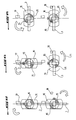
- la figure 5 est une vue éclatée en perspective agrandie de la partie cerclée en V de la figure 2 et représentant en partie les moyens de commande du pivotement des volets ;
- la figure 6 est une vue en perspective de la partie cerclée en VI de la figure 1 et représentant en partie les deux moyens de commande respectivement de deux volets adjacents occupant leur position de fermeture ;
- la figure 7 est une vue semblable à celle de la figure 6 et représentant l'un des volets en position d'ouverture ;
- la figure 8 est une vue semblable à celle de la figure 6 et représentant les deux volets à leur position d'ouverture ;
- les figures 9 à 11 représentent des ressorts de torsion utilisés dans les mécanismes de commande de pivotement des volets à des positions contraintes et non contrainte ; et
- les figures 12 à 14 représentent différentes phases de pivotement des volets de leur position de fermeture à leur position d'ouverture du cadre.
Claims (13)
- Dispositif de régulation d'un flux d'air entrant dans un espace plus ou moins clos, comprenant un support fixe (1) portant au moins un organe mobile commandé (3) déplaçable entre des positions de dégagement et d'obturation de l'ouverture (2) de passage du flux d'air délimitée par le support fixe (1), caractérisé en ce que l'organe mobile comprend un premier volet (3) monté pivotant entre deux éléments parallèles (4,5) du support fixe (1) autour de son axe longitudinal, l'une des extrémités pivotantes du volet (3) comprenant les moyens de commande du pivotement du volet constitués par une roue dentée (7) accouplée à un axe cylindrique (9) de l'extrémité du volet (3) monté à rotation dans l'élément correspondant (5), et une vis sans fin commandée (14) permettant l'entraínement de la roue dentée (7) dans un sens ou dans l'autre pour amener le volet (3) à sa position de dégagement ou d'obturation de l'ouverture (2) de passage du flux d'air, en ce qu'il comprend au moins un deuxième volet (3) monté pivotant entre les deux éléments parallèles (4,5) du support fixe (1) autour de son axe longitudinal en dessous du premier volet (3) de manière que les deux volets (3) soient disposés dans le même plan à leur position d'obturation de l'ouverture (2) de passage du flux d'air, et en ce que les moyens de commande du pivotement du deuxième volet comprennent une roue dentée (7) disposée en-dessous de la roue dentée (7) du premier volet (3) dans le même plan que cette dernière et accouplée à un axe cylindrique (9) de l'extrémité du deuxième volet (3) monté à rotation dans l'élément (5) du support fixe (1), et la vis sans fin (14) qui est commune aux deux roues dentées (7) et peut être commandée à des instants différents pour entraíner à l'unisson dans le même sens les deux roues dentées (7) de manière à amener dans un premier temps uniquement l'un des volets (3) à sa position de dégagement de l'ouverture (2) de passage du flux d'air pendant que l'autre volet (3) reste à sa position d'obturation de cette ouverture, puis dans un second temps l'autre volet (3) à sa position de dégagement de l'ouverture (2) pendant que le volet précédent (3) reste à sa position de dégagement de cette ouverture, ou réciproquement.
- Dispositif selon la revendication 1, caractérisé en ce que la vis sans fin (14) peut également être commandée pour entraíner à l'unisson dans le même sens les deux roues dentées (7) de manière à amener simultanément les deux volets (3) à leur position de dégagement ou d'obturation de l'ouverture (2) de passage du flux d'air suivant l'état qu'ils occupaient auparavant.
- Dispositif selon la revendication 1 ou 2, caractérisé en ce que le moyen d'accouplement de chaque roue dentée (7) à l'axe cylindrique (9) du volet correspondant (3) comprend deux doigts de crabotage (15) solidaires d'une face latérale de la roue dentée (7) en étant diamétralement opposés et disposés de part et d'autre de deux ailettes diamétralement opposées (16) solidaires de l'extrémité libre de l'axe cylindrique (9), les deux doigts de crabotage (15) étant en appui respectivement sur les deux faces alternes des ailettes (16), et en ce qu'en position d'obturation des volets (3), l'un d'eux est maintenu fermé par un ressort de rappel de torsion non contraint (13) interposé entre l'axe cylindrique (9) de ce volet et l'élément (5), et l'autre volet (3) est maintenu fermé par les deux doigts de crabotage (15) de la roue dentée correspondante (7) sur lesquels sont en appui les ailettes (16) de l'axe cylindrique (9) de ce volet sous l'action d'un autre ressort de rappel de torsion (13) interposé entre l'axe cylindrique (9) de l'autre volet (3) et l'élément (5) et qui est contraint dans un sens tendant à amener l'autre volet (3) à sa position de dégagement de l'ouverture (2).
- Dispositif selon la revendication 3, caractérisé en ce que lorsque la vis sans fin (14) est commandée pour amener successivement les deux volets (3) à leur position de dégagement de l'ouverture (2), les roues dentées (7) sont entraínées à chaque fois par la vis sans fin (14) de manière à provoquer une rotation de celles-ci de 90° et, dans le premier temps, les doigts de crabotage (15) de la roue dentée (7) du volet (3) restant à sa position d'obturation sont tournés pour les amener en appui sur les faces opposées des ailettes (16) de l'axe cylindrique (9) dont le ressort de rappel (13) reste non contraint et les doigts de crabotage (15) de l'autre roue dentée (7) de l'autre volet (7) sont également tournés dans le même sens à la même position angulaire que les précédents pour libérer le ressort de rappel contraint (13) qui provoque le pivotement de l'autre volet (3) à sa position de dégagement de l'ouverture (2) à laquelle il est maintenu par ce ressort (13) alors non contraint, puis, dans le second temps, les doigts de crabotage (15) de la roue dentée (7) du volet (3) maintenu à sa position d'obturation sont à nouveau tournés de manière à entraíner en rotation les ailettes (16) de l'axe cylindrique (9) de ce volet en contraignant le ressort de rappel associé (13) jusqu'à ce que le volet (3) occupe sa position de dégagement de l'ouverture (2) et les doigts de crabotage (15) de l'autre roue dentée (7) du volet (3) restant à sa position de dégagement sont tournés dans le même sens et à la même position angulaire que les précédents pour les amener en appui sur les faces opposées des ailettes (16) de l'axe cylindrique (9) dont le ressort de rappel (13) reste non contraint.
- Dispositif selon la revendication 3 ou 4, caractérisé en ce que chaque doigt de crabotage (15) présente en section transversale une forme en segment de cercle d'un angle au centre de 90°.
- Dispositif selon l'une des revendications 3 à 5, caractérisé en ce que les ressorts de rappel (13) sont en forme de bague fendue entourant leurs axes cylindriques respectifs (9) et dont l'une des extrémités (13a) est fixée à l'élément (5) du support fixe (1) et l'autre extrémité (13b) est fixée à l'axe cylindrique correspondant (9), la bague de chaque ressort de rappel (13) étant pratiquement fermée à sa position non contrainte, tandis que la bague du ressort de rappel contraint (13) associé au volet (3) maintenu avec l'autre volet (3) à sa position d'obturation de l'ouverture (2) est en partie enroulée sur elle-même et l'autre bague du ressort de rappel contraint (13) de l'autre volet amené à sa position de dégagement de l'ouverture (2) dans le second temps est ouverte élastiquement.
- Dispositif selon l'une des revendications précédentes, caractérisé en ce que chaque roue dentée (7) est montée à rotation sur un axe de support (8) immobilisé en translation par rapport à l'élément (5) et solidaire de l'axe cylindrique (9) du volet correspondant (3) coaxialement à ce dernier par une goupille (12) formée par une vis.
- Dispositif selon la revendication 7 lorsque considérée en combinaison avec la revendication 6, caractérisé en ce que l'extrémité (13b) de chaque bague de ressort de rappel (13) est fixée à une extrémité libre de la goupille (12) de l'axe cylindrique (9) du volet correspondant (3).
- Dispositif selon la revendication 7 ou 8, caractérisé en ce que l'axe de support (8) de chaque roue dentée (7) traverse cette dernière et l'élément (5) en étant monté à rotation sur ce dernier et est solidaire, à son extrémité opposée à l'axe cylindrique du volet correspondant (3), de l'extrémité d'un autre volet (3) situé dans le même plan que le précédent en prolongement de celui-ci et dont l'autre extrémité est montée pivotante sur un troisième élément (4) du support fixe (1) parallèle aux deux autres éléments de manière que ces deux volets puissent pivoter à l'unisson pour dégager ou obturer les ouvertures (2) délimitées entre les éléments (4,5).
- Dispositif selon l'une des revendications précédentes, caractérisé en ce que le support fixe (1) est en forme de cadre rectangulaire et peut être fixé derrière la grille de calandre avant d'entrée d'air circulant sous le capot d'un véhicule automobile.
- Dispositif selon l'une des revendications précédentes, caractérisé en ce que les volets (3) sont disposés sensiblement perpendiculairement au plan du cadre (1) à leur position de dégagement de l'ouverture (2) de passage du flux d'air.
- Dispositif selon l'une des revendications précédentes, caractérisé en ce que les éléments du support fixe (1) sont des montants de celui-ci.
- Véhicule automobile, caractérisé en ce qu'il est équipé d'un dispositif de régulation d'un flux d'air tel que défini dans l'une quelconque des revendications précédentes.
Applications Claiming Priority (2)
| Application Number | Priority Date | Filing Date | Title |
|---|---|---|---|
| FR0311666 | 2003-10-06 | ||
| FR0311666A FR2860575B1 (fr) | 2003-10-06 | 2003-10-06 | Dispositif de regulation d'un flux d'air entrant notamment sous le capot d'un vehicule automobile |
Publications (2)
| Publication Number | Publication Date |
|---|---|
| EP1522448A1 true EP1522448A1 (fr) | 2005-04-13 |
| EP1522448B1 EP1522448B1 (fr) | 2007-07-04 |
Family
ID=34307444
Family Applications (1)
| Application Number | Title | Priority Date | Filing Date |
|---|---|---|---|
| EP04292177A Not-in-force EP1522448B1 (fr) | 2003-10-06 | 2004-09-10 | Dispositif de régulation d'un flux d'air entrant notamment sous le capot d'un véhicule automobile |
Country Status (4)
| Country | Link |
|---|---|
| EP (1) | EP1522448B1 (fr) |
| AT (1) | ATE366197T1 (fr) |
| DE (1) | DE602004007338T2 (fr) |
| FR (1) | FR2860575B1 (fr) |
Cited By (16)
| Publication number | Priority date | Publication date | Assignee | Title |
|---|---|---|---|---|
| EP2193948A1 (fr) * | 2008-12-04 | 2010-06-09 | Faurecia Bloc Avant | Ensemble de carrosserie de véhicule automobile munie de volets montés en rotation |
| FR2939371A1 (fr) * | 2008-12-04 | 2010-06-11 | Faurecia Bloc Avant | Peau de pare-chocs de vehicule automobile munie de volets montes en rotation |
| EP2233343A2 (fr) | 2009-03-25 | 2010-09-29 | Aisin Seiki Kabushiki Kaisha | Dispositif d'obturateur de calandre amovible pour véhicule |
| CN101879917A (zh) * | 2009-05-07 | 2010-11-10 | F·波尔希名誉工学博士公司 | 用于机动车辆前罩板中的冷却风门模块的安装装置 |
| CN102198793A (zh) * | 2010-03-25 | 2011-09-28 | 爱信精机株式会社 | 用于车辆的可动格栅风门 |
| EP2407333A1 (fr) * | 2010-07-13 | 2012-01-18 | Aisin Seiki Kabushiki Kaisha | Obturateur de calandre amovible pour véhicule |
| DE102010060253A1 (de) * | 2010-10-29 | 2012-05-03 | Brose Fahrzeugteile Gmbh & Co. Kommanditgesellschaft, Coburg | Vorrichtung zur Einstellung einer Kühlluftzuströmung |
| US8561739B2 (en) | 2010-07-13 | 2013-10-22 | Aisin Seiki Kabushiki Kaisha | Movable grille shutter for vehicle |
| WO2015032990A1 (fr) * | 2013-09-09 | 2015-03-12 | Valeo Systemes Thermiques | Volet d'obturation de ventilation pour automobile |
| CN104507729A (zh) * | 2012-06-01 | 2015-04-08 | 荷兰反光镜控制器国际有限公司 | 调节装置、进气口及机动车 |
| WO2016188969A1 (fr) * | 2015-05-27 | 2016-12-01 | Valeo Klimasysteme Gmbh | Module de chauffage, ventilation et/ou climatisation d'un habitacle d'un véhicule automobile |
| EP3235671A1 (fr) * | 2016-04-19 | 2017-10-25 | Batz, S.Coop. | Dispositif d'obturation pour une calandre d'un véhicule |
| WO2019043315A1 (fr) * | 2017-09-01 | 2019-03-07 | Valeo Systemes Thermiques | Volet d'obturation pour dispositif de regulation d'un flux d'air pour module de face avant pour vehicule automobile |
| JP2019214288A (ja) * | 2018-06-12 | 2019-12-19 | 株式会社デンソー | シャッター装置 |
| FR3123261A1 (fr) * | 2021-05-31 | 2022-12-02 | Psa Automobiles Sa | Dispositif de régulation pilotée du flux d’air entrant d’un véhicule optimisé pour choc réparabilité |
| WO2023227362A1 (fr) * | 2022-05-24 | 2023-11-30 | Renault S.A.S | Cassette pour un dispositif de régulation de la circulation d'un flux d'air d'un vehicule automobile et volet pour une telle cassette |
Families Citing this family (10)
| Publication number | Priority date | Publication date | Assignee | Title |
|---|---|---|---|---|
| US8708078B2 (en) * | 2010-04-13 | 2014-04-29 | GM Global Technology Operations LLC | Flexible drive element for an angled active shutter |
| US20130264047A1 (en) * | 2012-04-10 | 2013-10-10 | GM Global Technology Operations LLC | Shielded positive stops for an active shutter |
| DE102012011594B4 (de) | 2012-06-13 | 2016-09-22 | Decoma (Germany) Gmbh | Steuerbarer Lufteinlass für ein Kraftfahrzeug mit Zylinderlamellen |
| DE102012011593B4 (de) | 2012-06-13 | 2017-10-19 | Magna Exteriors (Germany) Gmbh | Lastbegrenzer |
| DE102012011595B4 (de) | 2012-06-13 | 2016-09-15 | Decoma (Germany) Gmbh | Übertragungselement für einen steuerbaren Lufteinlass eines Kraftfahrzeugs |
| DE102012214474B4 (de) | 2012-08-14 | 2017-08-31 | Magna Exteriors (Germany) Gmbh | Steuerbarer Lufteinlass für ein Kraftfahrzeug |
| DE102015101213A1 (de) | 2015-01-28 | 2016-07-28 | Dr. Ing. H.C. F. Porsche Aktiengesellschaft | Bugteil eines Kraftfahrzeugs |
| DE102016225074A1 (de) | 2016-12-15 | 2018-06-21 | Bayerische Motoren Werke Aktiengesellschaft | Luftklappenaufbau für ein Kraftfahrzeug-Klimamodul |
| DE102016225112A1 (de) * | 2016-12-15 | 2018-06-21 | Röchling Automotive SE & Co. KG | Luftklappenvorrichtung mit einer Mehrzahl von Luftklappen mit sequenziell endender Luftklappenbewegung |
| FR3094674B1 (fr) * | 2019-04-03 | 2021-04-16 | Flex N Gate France | Dispositif d’aération pour un véhicule, procédé de montage associé |
Citations (2)
| Publication number | Priority date | Publication date | Assignee | Title |
|---|---|---|---|---|
| DE3522591A1 (de) * | 1985-06-25 | 1987-01-08 | Sueddeutsche Kuehler Behr | Kuehler fuer eine brennkraftmaschine mit einer jalousie |
| US5732666A (en) * | 1996-06-11 | 1998-03-31 | Hyundai Motor Company | Device for moving a radiator grille in an automobile |
-
2003
- 2003-10-06 FR FR0311666A patent/FR2860575B1/fr not_active Expired - Fee Related
-
2004
- 2004-09-10 EP EP04292177A patent/EP1522448B1/fr not_active Not-in-force
- 2004-09-10 DE DE602004007338T patent/DE602004007338T2/de active Active
- 2004-09-10 AT AT04292177T patent/ATE366197T1/de not_active IP Right Cessation
Patent Citations (2)
| Publication number | Priority date | Publication date | Assignee | Title |
|---|---|---|---|---|
| DE3522591A1 (de) * | 1985-06-25 | 1987-01-08 | Sueddeutsche Kuehler Behr | Kuehler fuer eine brennkraftmaschine mit einer jalousie |
| US5732666A (en) * | 1996-06-11 | 1998-03-31 | Hyundai Motor Company | Device for moving a radiator grille in an automobile |
Cited By (32)
| Publication number | Priority date | Publication date | Assignee | Title |
|---|---|---|---|---|
| FR2939373A1 (fr) * | 2008-12-04 | 2010-06-11 | Faurecia Bloc Avant | Ensemble de carrosserie de vehicule automobile munie de volets montes en rotation |
| FR2939371A1 (fr) * | 2008-12-04 | 2010-06-11 | Faurecia Bloc Avant | Peau de pare-chocs de vehicule automobile munie de volets montes en rotation |
| EP2193948A1 (fr) * | 2008-12-04 | 2010-06-09 | Faurecia Bloc Avant | Ensemble de carrosserie de véhicule automobile munie de volets montés en rotation |
| EP2233343A2 (fr) | 2009-03-25 | 2010-09-29 | Aisin Seiki Kabushiki Kaisha | Dispositif d'obturateur de calandre amovible pour véhicule |
| EP2233343A3 (fr) * | 2009-03-25 | 2010-12-15 | Aisin Seiki Kabushiki Kaisha | Dispositif d'obturateur de calandre amovible pour véhicule |
| CN101879917B (zh) * | 2009-05-07 | 2012-11-14 | F·波尔希名誉工学博士公司 | 用于机动车辆前罩板中的冷却风门模块的安装装置 |
| CN101879917A (zh) * | 2009-05-07 | 2010-11-10 | F·波尔希名誉工学博士公司 | 用于机动车辆前罩板中的冷却风门模块的安装装置 |
| US8752886B2 (en) | 2009-05-07 | 2014-06-17 | Dr. Ing. H.C. F. Porsche Aktiengesellschaft | Mounting module for a cooling air flap module in a front panel of a motor vehicle |
| CN102198793A (zh) * | 2010-03-25 | 2011-09-28 | 爱信精机株式会社 | 用于车辆的可动格栅风门 |
| US20110232981A1 (en) * | 2010-03-25 | 2011-09-29 | Aisin Seiki Kabushiki Kaisha. | Movable grille shutter for vehicle |
| EP2407333A1 (fr) * | 2010-07-13 | 2012-01-18 | Aisin Seiki Kabushiki Kaisha | Obturateur de calandre amovible pour véhicule |
| US8561739B2 (en) | 2010-07-13 | 2013-10-22 | Aisin Seiki Kabushiki Kaisha | Movable grille shutter for vehicle |
| DE102010060253A1 (de) * | 2010-10-29 | 2012-05-03 | Brose Fahrzeugteile Gmbh & Co. Kommanditgesellschaft, Coburg | Vorrichtung zur Einstellung einer Kühlluftzuströmung |
| JP2015525166A (ja) * | 2012-06-01 | 2015-09-03 | エムシーアイ(ミラー コントロールズ インターナショナル)ネザーランド ベー.フェー. | 調整装置、吸気口、および自動車 |
| CN104507729A (zh) * | 2012-06-01 | 2015-04-08 | 荷兰反光镜控制器国际有限公司 | 调节装置、进气口及机动车 |
| FR3010502A1 (fr) * | 2013-09-09 | 2015-03-13 | Valeo Systemes Thermiques | Volet d'obturation de ventilation pour automobile |
| WO2015032990A1 (fr) * | 2013-09-09 | 2015-03-12 | Valeo Systemes Thermiques | Volet d'obturation de ventilation pour automobile |
| CN105555574A (zh) * | 2013-09-09 | 2016-05-04 | 法雷奥热系统公司 | 用于汽车的通风关闭瓣片 |
| CN107667022B (zh) * | 2015-05-27 | 2021-02-19 | 法雷奥空调系统有限责任公司 | 用于机动车辆乘客舱的供暖、通风和/或空调的模块 |
| CN107667022A (zh) * | 2015-05-27 | 2018-02-06 | 法雷奥空调系统有限责任公司 | 用于机动车辆乘客舱的供暖、通风和/或空调的模块 |
| WO2016188969A1 (fr) * | 2015-05-27 | 2016-12-01 | Valeo Klimasysteme Gmbh | Module de chauffage, ventilation et/ou climatisation d'un habitacle d'un véhicule automobile |
| CN107303813B (zh) * | 2016-04-19 | 2021-11-23 | 巴兹联合公司 | 用于车辆的前格栅的遮蔽器装置 |
| CN107303813A (zh) * | 2016-04-19 | 2017-10-31 | 巴兹联合公司 | 用于车辆的前格栅的遮蔽器装置 |
| US10166858B2 (en) | 2016-04-19 | 2019-01-01 | Batz, S.Coop. | Shutter device for a front grille of a vehicle |
| EP3235671A1 (fr) * | 2016-04-19 | 2017-10-25 | Batz, S.Coop. | Dispositif d'obturation pour une calandre d'un véhicule |
| WO2019043315A1 (fr) * | 2017-09-01 | 2019-03-07 | Valeo Systemes Thermiques | Volet d'obturation pour dispositif de regulation d'un flux d'air pour module de face avant pour vehicule automobile |
| FR3070633A1 (fr) * | 2017-09-01 | 2019-03-08 | Valeo Systemes Thermiques | Volet d'obturation pour dispositif de regulation d'un flux d'air pour module de face avant pour vehicule automobile |
| JP2019214288A (ja) * | 2018-06-12 | 2019-12-19 | 株式会社デンソー | シャッター装置 |
| FR3123261A1 (fr) * | 2021-05-31 | 2022-12-02 | Psa Automobiles Sa | Dispositif de régulation pilotée du flux d’air entrant d’un véhicule optimisé pour choc réparabilité |
| WO2022254110A1 (fr) * | 2021-05-31 | 2022-12-08 | Psa Automobiles Sa | Dispositif de régulation pilotée du flux d'air entrant d'un véhicule optimisé pour choc réparabilité |
| WO2023227362A1 (fr) * | 2022-05-24 | 2023-11-30 | Renault S.A.S | Cassette pour un dispositif de régulation de la circulation d'un flux d'air d'un vehicule automobile et volet pour une telle cassette |
| FR3136048A1 (fr) * | 2022-05-24 | 2023-12-01 | Renault S.A.S. | Cassette pour un dispositif de régulation de la circulation d’un flux d’air d’un véhicule automobile et volet pour une telle cassette. |
Also Published As
| Publication number | Publication date |
|---|---|
| DE602004007338T2 (de) | 2008-03-06 |
| FR2860575B1 (fr) | 2006-10-27 |
| FR2860575A1 (fr) | 2005-04-08 |
| ATE366197T1 (de) | 2007-07-15 |
| DE602004007338D1 (de) | 2007-08-16 |
| EP1522448B1 (fr) | 2007-07-04 |
Similar Documents
| Publication | Publication Date | Title |
|---|---|---|
| EP1522448B1 (fr) | Dispositif de régulation d'un flux d'air entrant notamment sous le capot d'un véhicule automobile | |
| EP2010774A1 (fr) | Vanne a deux papillons actionnes par un moteur commun | |
| FR2558968A1 (fr) | Element de support et d'actionnement pour un dispositif a miroir | |
| WO2005021329A1 (fr) | Dispositif de vision arriere pour vehicule automobile | |
| EP0500430A1 (fr) | Dispositif à volets pivotants pour la régulation du débit d'air traversant un échangeur de chaleur | |
| FR2825326A1 (fr) | Dispositif de regulation d'un flux d'air circulant a travers une ouverture d'un vehicule automobile | |
| WO2020109685A1 (fr) | Aerateur mince a effet coanda pour vehicule automobile | |
| EP3393835B1 (fr) | Dispositif d'ouverture et de fermeture en séquence de volets d'air | |
| EP2769862A1 (fr) | Dispositif diffuseur de parfum dans l'habitacle d'un véhicule, tel qu'un véhicule automobile | |
| EP0125976A1 (fr) | Dispositif à volets pour distribuer le flux d'air dans une installation de climatisation de véhicule automobile | |
| WO2018078261A1 (fr) | Dispositif de contrôle de volet notamment pour véhicule automobile, et cadre comprenant un tel dispositif | |
| FR3102102A1 (fr) | Dispositif d’obturation pour entrée d’air de face avant de véhicule automobile comportant un dispositif de désolidarisation de volet | |
| FR2901005A1 (fr) | Butee haute pour vanne rotative | |
| FR3066565A1 (fr) | Dispositif de liaison actionneur-levier pour dispositif d'obturation de face avant de vehicule automobile, et dispositif d'obturation de face avant associe | |
| FR3068921B1 (fr) | Dispositif de liaison actionneur-levier pour dispositif d'obturation de face avant de vehicule automobile, et dispositif d'obturation de face avant associe | |
| EP4116126B1 (fr) | Dispositif d'obturation d'entrée d'air pour un véhicule automobile avec système de rappel automatique | |
| EP1132228A1 (fr) | Installation de ventilation de l'habitacle d'un véhicule automobile | |
| EP1657398A2 (fr) | Dispositif d'entrainement pour tablier de volet roulant | |
| EP0477047B1 (fr) | Dispositif de réglage de la température d'un système de climatisation, par exemple pour un véhicule automobile | |
| EP3297593B1 (fr) | Fauteuil roulant | |
| FR2783866A1 (fr) | Electro-reducteur pour l'automatisation de volets roulants | |
| WO2003070502A1 (fr) | Dispositif de reglage de l'ouverture d'entree d'air a travers un pare-chocs avant de vehicule | |
| WO2019202247A1 (fr) | Ensemble de volets mobiles pour un dispositif de regulation d'un flux d'air pour un vehicule automobile | |
| FR3077034A1 (fr) | Arbre d’entrainement et dispositif de controle de volet correspondant | |
| FR3056944A1 (fr) | Mecanisme d'articulation pour siege de vehicule et siege comportant un tel mecanisme d'articulation |
Legal Events
| Date | Code | Title | Description |
|---|---|---|---|
| PUAI | Public reference made under article 153(3) epc to a published international application that has entered the european phase |
Free format text: ORIGINAL CODE: 0009012 |
|
| AK | Designated contracting states |
Kind code of ref document: A1 Designated state(s): AT BE BG CH CY CZ DE DK EE ES FI FR GB GR HU IE IT LI LU MC NL PL PT RO SE SI SK TR |
|
| AX | Request for extension of the european patent |
Extension state: AL HR LT LV MK |
|
| 17P | Request for examination filed |
Effective date: 20050913 |
|
| AKX | Designation fees paid |
Designated state(s): AT BE BG CH CY CZ DE DK EE ES FI FR GB GR HU IE IT LI LU MC NL PL PT RO SE SI SK TR |
|
| GRAP | Despatch of communication of intention to grant a patent |
Free format text: ORIGINAL CODE: EPIDOSNIGR1 |
|
| GRAS | Grant fee paid |
Free format text: ORIGINAL CODE: EPIDOSNIGR3 |
|
| GRAA | (expected) grant |
Free format text: ORIGINAL CODE: 0009210 |
|
| AK | Designated contracting states |
Kind code of ref document: B1 Designated state(s): AT BE BG CH CY CZ DE DK EE ES FI FR GB GR HU IE IT LI LU MC NL PL PT RO SE SI SK TR |
|
| REG | Reference to a national code |
Ref country code: GB Ref legal event code: FG4D Free format text: NOT ENGLISH |
|
| REG | Reference to a national code |
Ref country code: CH Ref legal event code: EP |
|
| REG | Reference to a national code |
Ref country code: IE Ref legal event code: FG4D Free format text: LANGUAGE OF EP DOCUMENT: FRENCH |
|
| REF | Corresponds to: |
Ref document number: 602004007338 Country of ref document: DE Date of ref document: 20070816 Kind code of ref document: P |
|
| GBT | Gb: translation of ep patent filed (gb section 77(6)(a)/1977) |
Effective date: 20071004 |
|
| NLV1 | Nl: lapsed or annulled due to failure to fulfill the requirements of art. 29p and 29m of the patents act | ||
| PG25 | Lapsed in a contracting state [announced via postgrant information from national office to epo] |
Ref country code: BG Free format text: LAPSE BECAUSE OF FAILURE TO SUBMIT A TRANSLATION OF THE DESCRIPTION OR TO PAY THE FEE WITHIN THE PRESCRIBED TIME-LIMIT Effective date: 20071004 Ref country code: PT Free format text: LAPSE BECAUSE OF FAILURE TO SUBMIT A TRANSLATION OF THE DESCRIPTION OR TO PAY THE FEE WITHIN THE PRESCRIBED TIME-LIMIT Effective date: 20071204 Ref country code: NL Free format text: LAPSE BECAUSE OF FAILURE TO SUBMIT A TRANSLATION OF THE DESCRIPTION OR TO PAY THE FEE WITHIN THE PRESCRIBED TIME-LIMIT Effective date: 20070704 Ref country code: SI Free format text: LAPSE BECAUSE OF FAILURE TO SUBMIT A TRANSLATION OF THE DESCRIPTION OR TO PAY THE FEE WITHIN THE PRESCRIBED TIME-LIMIT Effective date: 20070704 Ref country code: ES Free format text: LAPSE BECAUSE OF FAILURE TO SUBMIT A TRANSLATION OF THE DESCRIPTION OR TO PAY THE FEE WITHIN THE PRESCRIBED TIME-LIMIT Effective date: 20071015 Ref country code: FI Free format text: LAPSE BECAUSE OF FAILURE TO SUBMIT A TRANSLATION OF THE DESCRIPTION OR TO PAY THE FEE WITHIN THE PRESCRIBED TIME-LIMIT Effective date: 20070704 |
|
| PG25 | Lapsed in a contracting state [announced via postgrant information from national office to epo] |
Ref country code: PL Free format text: LAPSE BECAUSE OF FAILURE TO SUBMIT A TRANSLATION OF THE DESCRIPTION OR TO PAY THE FEE WITHIN THE PRESCRIBED TIME-LIMIT Effective date: 20070704 Ref country code: AT Free format text: LAPSE BECAUSE OF FAILURE TO SUBMIT A TRANSLATION OF THE DESCRIPTION OR TO PAY THE FEE WITHIN THE PRESCRIBED TIME-LIMIT Effective date: 20070704 |
|
| REG | Reference to a national code |
Ref country code: IE Ref legal event code: FD4D |
|
| BERE | Be: lapsed |
Owner name: PEUGEOT CITROEN AUTOMOBILES S.A. Effective date: 20070930 |
|
| PG25 | Lapsed in a contracting state [announced via postgrant information from national office to epo] |
Ref country code: GR Free format text: LAPSE BECAUSE OF FAILURE TO SUBMIT A TRANSLATION OF THE DESCRIPTION OR TO PAY THE FEE WITHIN THE PRESCRIBED TIME-LIMIT Effective date: 20071005 Ref country code: MC Free format text: LAPSE BECAUSE OF NON-PAYMENT OF DUE FEES Effective date: 20070930 Ref country code: DK Free format text: LAPSE BECAUSE OF FAILURE TO SUBMIT A TRANSLATION OF THE DESCRIPTION OR TO PAY THE FEE WITHIN THE PRESCRIBED TIME-LIMIT Effective date: 20070704 |
|
| PLBE | No opposition filed within time limit |
Free format text: ORIGINAL CODE: 0009261 |
|
| STAA | Information on the status of an ep patent application or granted ep patent |
Free format text: STATUS: NO OPPOSITION FILED WITHIN TIME LIMIT |
|
| PG25 | Lapsed in a contracting state [announced via postgrant information from national office to epo] |
Ref country code: SK Free format text: LAPSE BECAUSE OF FAILURE TO SUBMIT A TRANSLATION OF THE DESCRIPTION OR TO PAY THE FEE WITHIN THE PRESCRIBED TIME-LIMIT Effective date: 20070704 Ref country code: IE Free format text: LAPSE BECAUSE OF FAILURE TO SUBMIT A TRANSLATION OF THE DESCRIPTION OR TO PAY THE FEE WITHIN THE PRESCRIBED TIME-LIMIT Effective date: 20070704 Ref country code: CZ Free format text: LAPSE BECAUSE OF FAILURE TO SUBMIT A TRANSLATION OF THE DESCRIPTION OR TO PAY THE FEE WITHIN THE PRESCRIBED TIME-LIMIT Effective date: 20070704 |
|
| 26N | No opposition filed |
Effective date: 20080407 |
|
| PG25 | Lapsed in a contracting state [announced via postgrant information from national office to epo] |
Ref country code: RO Free format text: LAPSE BECAUSE OF FAILURE TO SUBMIT A TRANSLATION OF THE DESCRIPTION OR TO PAY THE FEE WITHIN THE PRESCRIBED TIME-LIMIT Effective date: 20070704 Ref country code: SE Free format text: LAPSE BECAUSE OF FAILURE TO SUBMIT A TRANSLATION OF THE DESCRIPTION OR TO PAY THE FEE WITHIN THE PRESCRIBED TIME-LIMIT Effective date: 20071004 |
|
| PG25 | Lapsed in a contracting state [announced via postgrant information from national office to epo] |
Ref country code: BE Free format text: LAPSE BECAUSE OF NON-PAYMENT OF DUE FEES Effective date: 20070930 |
|
| PG25 | Lapsed in a contracting state [announced via postgrant information from national office to epo] |
Ref country code: EE Free format text: LAPSE BECAUSE OF FAILURE TO SUBMIT A TRANSLATION OF THE DESCRIPTION OR TO PAY THE FEE WITHIN THE PRESCRIBED TIME-LIMIT Effective date: 20070704 |
|
| REG | Reference to a national code |
Ref country code: CH Ref legal event code: PL |
|
| PG25 | Lapsed in a contracting state [announced via postgrant information from national office to epo] |
Ref country code: LI Free format text: LAPSE BECAUSE OF NON-PAYMENT OF DUE FEES Effective date: 20070930 Ref country code: CH Free format text: LAPSE BECAUSE OF NON-PAYMENT OF DUE FEES Effective date: 20070930 |
|
| PG25 | Lapsed in a contracting state [announced via postgrant information from national office to epo] |
Ref country code: CY Free format text: LAPSE BECAUSE OF FAILURE TO SUBMIT A TRANSLATION OF THE DESCRIPTION OR TO PAY THE FEE WITHIN THE PRESCRIBED TIME-LIMIT Effective date: 20070704 |
|
| PG25 | Lapsed in a contracting state [announced via postgrant information from national office to epo] |
Ref country code: LU Free format text: LAPSE BECAUSE OF NON-PAYMENT OF DUE FEES Effective date: 20070910 |
|
| PG25 | Lapsed in a contracting state [announced via postgrant information from national office to epo] |
Ref country code: HU Free format text: LAPSE BECAUSE OF FAILURE TO SUBMIT A TRANSLATION OF THE DESCRIPTION OR TO PAY THE FEE WITHIN THE PRESCRIBED TIME-LIMIT Effective date: 20080105 Ref country code: TR Free format text: LAPSE BECAUSE OF FAILURE TO SUBMIT A TRANSLATION OF THE DESCRIPTION OR TO PAY THE FEE WITHIN THE PRESCRIBED TIME-LIMIT Effective date: 20070704 |
|
| PG25 | Lapsed in a contracting state [announced via postgrant information from national office to epo] |
Ref country code: LI Free format text: LAPSE BECAUSE OF NON-PAYMENT OF DUE FEES Effective date: 20080930 Ref country code: CH Free format text: LAPSE BECAUSE OF NON-PAYMENT OF DUE FEES Effective date: 20080930 |
|
| PG25 | Lapsed in a contracting state [announced via postgrant information from national office to epo] |
Ref country code: IT Free format text: LAPSE BECAUSE OF NON-PAYMENT OF DUE FEES Effective date: 20070930 |
|
| PGFP | Annual fee paid to national office [announced via postgrant information from national office to epo] |
Ref country code: GB Payment date: 20120828 Year of fee payment: 9 |
|
| PGFP | Annual fee paid to national office [announced via postgrant information from national office to epo] |
Ref country code: DE Payment date: 20120827 Year of fee payment: 9 Ref country code: FR Payment date: 20121004 Year of fee payment: 9 |
|
| GBPC | Gb: european patent ceased through non-payment of renewal fee |
Effective date: 20130910 |
|
| REG | Reference to a national code |
Ref country code: DE Ref legal event code: R119 Ref document number: 602004007338 Country of ref document: DE Effective date: 20140401 |
|
| REG | Reference to a national code |
Ref country code: FR Ref legal event code: ST Effective date: 20140530 |
|
| PG25 | Lapsed in a contracting state [announced via postgrant information from national office to epo] |
Ref country code: GB Free format text: LAPSE BECAUSE OF NON-PAYMENT OF DUE FEES Effective date: 20130910 |
|
| PG25 | Lapsed in a contracting state [announced via postgrant information from national office to epo] |
Ref country code: DE Free format text: LAPSE BECAUSE OF NON-PAYMENT OF DUE FEES Effective date: 20140401 Ref country code: FR Free format text: LAPSE BECAUSE OF NON-PAYMENT OF DUE FEES Effective date: 20130930 |