EP1522437A1 - Luftversorgungseinrichtung zur Klimatisierung eines Fahrzeuginnenraums eines Fahrzeugs, insbesondere eines Nutzfahrzeuges - Google Patents
Luftversorgungseinrichtung zur Klimatisierung eines Fahrzeuginnenraums eines Fahrzeugs, insbesondere eines Nutzfahrzeuges Download PDFInfo
- Publication number
- EP1522437A1 EP1522437A1 EP04021650A EP04021650A EP1522437A1 EP 1522437 A1 EP1522437 A1 EP 1522437A1 EP 04021650 A EP04021650 A EP 04021650A EP 04021650 A EP04021650 A EP 04021650A EP 1522437 A1 EP1522437 A1 EP 1522437A1
- Authority
- EP
- European Patent Office
- Prior art keywords
- air
- headliner
- air duct
- supply device
- air supply
- Prior art date
- Legal status (The legal status is an assumption and is not a legal conclusion. Google has not performed a legal analysis and makes no representation as to the accuracy of the status listed.)
- Granted
Links
- 238000004378 air conditioning Methods 0.000 title abstract description 13
- 238000009826 distribution Methods 0.000 claims abstract description 45
- 238000009423 ventilation Methods 0.000 claims abstract description 23
- 238000004519 manufacturing process Methods 0.000 claims description 8
- 239000004033 plastic Substances 0.000 claims description 7
- 229920003023 plastic Polymers 0.000 claims description 7
- 229920002522 Wood fibre Polymers 0.000 claims description 5
- 239000002025 wood fiber Substances 0.000 claims description 5
- 238000006073 displacement reaction Methods 0.000 claims description 4
- 239000000463 material Substances 0.000 claims description 4
- -1 polyethylene Polymers 0.000 claims description 4
- 238000004026 adhesive bonding Methods 0.000 claims description 3
- 238000003466 welding Methods 0.000 claims description 3
- 239000004698 Polyethylene Substances 0.000 claims description 2
- 239000004743 Polypropylene Substances 0.000 claims description 2
- 239000006260 foam Substances 0.000 claims description 2
- 239000002984 plastic foam Substances 0.000 claims description 2
- 229920000573 polyethylene Polymers 0.000 claims description 2
- 229920001155 polypropylene Polymers 0.000 claims description 2
- 230000015572 biosynthetic process Effects 0.000 claims 1
- 230000003750 conditioning effect Effects 0.000 claims 1
- 238000005755 formation reaction Methods 0.000 claims 1
- 238000010137 moulding (plastic) Methods 0.000 description 7
- 238000010276 construction Methods 0.000 description 5
- 239000000243 solution Substances 0.000 description 5
- 238000000071 blow moulding Methods 0.000 description 2
- 230000008878 coupling Effects 0.000 description 2
- 238000010168 coupling process Methods 0.000 description 2
- 238000005859 coupling reaction Methods 0.000 description 2
- 239000011094 fiberboard Substances 0.000 description 2
- 238000009434 installation Methods 0.000 description 2
- 238000004080 punching Methods 0.000 description 2
- 238000005452 bending Methods 0.000 description 1
- 238000005253 cladding Methods 0.000 description 1
- 238000005516 engineering process Methods 0.000 description 1
- 239000012530 fluid Substances 0.000 description 1
- 230000004927 fusion Effects 0.000 description 1
- 238000002347 injection Methods 0.000 description 1
- 239000007924 injection Substances 0.000 description 1
- 238000009413 insulation Methods 0.000 description 1
- 230000010354 integration Effects 0.000 description 1
- 238000004091 panning Methods 0.000 description 1
- 239000002244 precipitate Substances 0.000 description 1
- 238000007789 sealing Methods 0.000 description 1
- 230000000007 visual effect Effects 0.000 description 1
Images


Classifications
-
- B—PERFORMING OPERATIONS; TRANSPORTING
- B60—VEHICLES IN GENERAL
- B60H—ARRANGEMENTS OF HEATING, COOLING, VENTILATING OR OTHER AIR-TREATING DEVICES SPECIALLY ADAPTED FOR PASSENGER OR GOODS SPACES OF VEHICLES
- B60H1/00—Heating, cooling or ventilating [HVAC] devices
- B60H1/00507—Details, e.g. mounting arrangements, desaeration devices
- B60H1/00557—Details of ducts or cables
- B60H1/00564—Details of ducts or cables of air ducts
-
- B—PERFORMING OPERATIONS; TRANSPORTING
- B60—VEHICLES IN GENERAL
- B60H—ARRANGEMENTS OF HEATING, COOLING, VENTILATING OR OTHER AIR-TREATING DEVICES SPECIALLY ADAPTED FOR PASSENGER OR GOODS SPACES OF VEHICLES
- B60H1/00—Heating, cooling or ventilating [HVAC] devices
- B60H1/00357—Air-conditioning arrangements specially adapted for particular vehicles
- B60H1/00378—Air-conditioning arrangements specially adapted for particular vehicles for tractor or load vehicle cabins
-
- B—PERFORMING OPERATIONS; TRANSPORTING
- B60—VEHICLES IN GENERAL
- B60H—ARRANGEMENTS OF HEATING, COOLING, VENTILATING OR OTHER AIR-TREATING DEVICES SPECIALLY ADAPTED FOR PASSENGER OR GOODS SPACES OF VEHICLES
- B60H1/00—Heating, cooling or ventilating [HVAC] devices
- B60H1/24—Devices purely for ventilating or where the heating or cooling is irrelevant
- B60H1/241—Devices purely for ventilating or where the heating or cooling is irrelevant characterised by the location of ventilation devices in the vehicle
- B60H1/243—Devices purely for ventilating or where the heating or cooling is irrelevant characterised by the location of ventilation devices in the vehicle located in the lateral area (e.g. doors, pillars)
-
- B—PERFORMING OPERATIONS; TRANSPORTING
- B60—VEHICLES IN GENERAL
- B60H—ARRANGEMENTS OF HEATING, COOLING, VENTILATING OR OTHER AIR-TREATING DEVICES SPECIALLY ADAPTED FOR PASSENGER OR GOODS SPACES OF VEHICLES
- B60H1/00—Heating, cooling or ventilating [HVAC] devices
- B60H1/24—Devices purely for ventilating or where the heating or cooling is irrelevant
- B60H1/241—Devices purely for ventilating or where the heating or cooling is irrelevant characterised by the location of ventilation devices in the vehicle
- B60H1/245—Devices purely for ventilating or where the heating or cooling is irrelevant characterised by the location of ventilation devices in the vehicle located in the roof
Definitions
- the invention relates to an air supply device for air conditioning a Vehicle interior of a vehicle, in particular a commercial vehicle, after the Preamble of claim 1.
- a U-shape having air distribution channel along a fond Schoen rear headliner edge area on the headliner top arranged.
- This air distribution channel is via a lateral rear vertical column with Air is supplied to the air via the air distribution channel to the individual Outlet nozzles that emanate into the vehicle interior, distribute.
- a headliner for a car is known, the one multilayer cladding element with a deformable middle carrier layer made of foamed plastic, arranged on both sides of the carrier layer another also deformable layers and with a vehicle interior facing decorative layer.
- a multi-layered chamber element On the side facing away from the vehicle interior of the Headliner is a multi-layered chamber element with a malleable middle Carrier layer of foamed plastic with both sides of the carrier layer arranged arranged further also deformable layers.
- the Chamber element is connected to flange areas with the headliner and limited together with the headliner one or more air chambers. The air chambers open into air openings, which are recessed in the headliner.
- a headliner for a car is also known, the one Air distribution chamber having a in the direction of the surface area of the Headliner surface extending air outlet wall adjacent to the passenger compartment.
- This air outlet wall is perforated with a plurality of finely distributed apertures, by which the air distribution of the air supply device supplied Air with essentially flatly extended air fronts in the passenger compartment entry.
- the air supply takes place via the cavities of the C-pillar or A-pillar.
- the object of the invention is to provide an air supply device for air conditioning Vehicle interior of a vehicle, in particular a commercial vehicle to develop, with an interior ventilation and air conditioning on simple, inexpensive and functionally safe manner is possible and further also with low Assembly effort is mountable.
- the air supply device has a in the vehicle interior extending air duct, which in the assembled state with a Air duct longitudinal side along a vehicle interior facing Roof sky base extends. This is along the Headliner extending air duct on the one hand indirectly or directly with the ventilation source and on the other hand by means of at least one Air duct connection element directly or indirectly with at least one Air distribution channel coupled on the headliner top.
- Such a construction of an air supply device allows a particularly cost-effective solution, especially for commercial vehicles, with a lower Interior comfort to be equipped, since such a structure Air supply device can be easily built and therefore fast and can be inexpensively mounted in the vehicle. That is, that in this inventive solution of the air duct from the vehicle interior remains visible, so that z. B. no consuming and therefore costly constructive solutions are required to control the airflow to the air distribution ducts concealed.
- the at least one air duct channel connection element by appropriate Connection element recess openings in the roof lining preferably positive fit and / or tightly guided and coupled to the air distribution channel.
- Terminal element recess openings can in the headliner example, on simple manner be formed by punching, z. B. in conjunction with a Headliner, which is formed by a flexible flat plate, z. B. a fiberboard, due to their flexibility in the context of assembly simply in the desired Position can be bent.
- a simple and fast Mounting of the ventilation system allows the air duct by means of at least one quick connection to the headliner releasably latched and / or locked become.
- the connection of the air duct on Headliner by means of at least one plug-in and sliding connection.
- This Steckund Sliding connection is preferably designed so that the air duct to Training the respective plug and slide connection a bolt is provided, the a bolt web and a comparatively wider bolt head, wherein the Bolt with the bolt head through a roof liner side bolt receptacle keyhole-like Dachhimmelaus principleung to which a against the Bolt head narrower and the dimensions approximately to the stud web adapted groove-shaped slot area connects, is pluggable.
- the assembly therefore only needs of the worker Air duct set, inserted and then moved to the end position be set to this on the headliner.
- a plug-in and sliding connection on an outer wall area the air duct spaced from the at least one air duct connecting element be arranged.
- An advantageous functional integration results however, if the plug and slide connection to the air duct in the area the air duct duct connection element is formed.
- the air duct after making the quick connection with the Roof lining also z. B. by means of at least one fixing screw on the headliner still be fixed.
- This fixing screw is preferably in the range of one of Provided ventilation source opposite free air duct end. Also
- the reliability in the context of attachment of the air duct be significantly increased again on the headliner.
- connection element recess opening region in Headliner but also for the production of a rattle-free construction can be one around the Air duct connection element annularly guided seal provided be in the assembled state on the one hand on a roof sky underside Recess opening edge area and on the other hand at a corresponding associated air duct region, preferably by a Outside wall portion of the air duct is formed, tightly pressed pressed.
- the at least one air duct connection element is preferred by a Formed connecting piece, which protrudes from the air duct side wall area.
- a Formed connecting piece which protrudes from the air duct side wall area.
- z. B. may be provided a rectangular cross-section.
- an air duct provided in the vehicle interior at the headliner side edge in the roof near the area extending in the vehicle longitudinal direction.
- the arrangement can be preferably done in Anlagenfond Scheme. With such a laterally in the Vehicle interior lying air duct is achieved that in the Vehicle interior existing loading height and / or the head clearance between a Vehicle occupants and the headliner by the at the headliner base extending air duct is not reduced. Because of the lateral arrangement the air duct is sure to be outside of this relevant area runs.
- this extends laterally at the edge in the vehicle interior arranged air duct to approximately in the range of a vertical column and is by means of a ventilation source arranged there, z. B. coupled to a blower.
- the Air duct in Vietnamesefond Scheme a combined or commercial vehicle up in extends approximately to a D-pillar and arranged there in the D-pillar Blower device is coupled.
- a Wheelbase of the air duct indirectly by means of at least one along the Vertical column and / or but also a Dachholmend Scheme in Vehicle longitudinal direction extending air duct element with the ventilation source be coupled.
- the Headliner arranged at least one air distribution duct over the Headliner between opposite sides of the vehicle in the vehicle transverse direction, most preferably in an unreinforced vehicle roof area, i. H. spaced from the roof bows.
- a headliner structure is possible, as much as possible Loading height and headroom in the vehicle interior allows.
- the course in the vehicle transverse direction good results in terms of a uniform vehicle air conditioning in this vehicle area.
- a rear area on the headliner top at least two Air distribution channels provided which are spaced from each other and approximately parallel are aligned with each other and in the vehicle transverse direction between opposite vehicle sides on the headliner top run. Each this separate air distribution channels is by means of a separate air duct connection element fluidly connected to the air duct. This will be a created advantageous construction that is easy to implement.
- the air distribution channel has advantageously in cross section a downwardly open U-shaped Profile on, preferably a so-called hat-shaped profile with mounting flanges at the free ends, so that the covered roof sky top area component the top air duct is.
- Such air distribution channel can be simple Way quickly and functionally by gluing and / or fusing and / or Tacking and / or welding to be connected to the headliner top.
- a particularly inexpensive and low-weight construction arises when the at least one air distribution channel z. B. from a plastic foam, z. B. one Polyethylene foam is made.
- Such air distribution channels can be advantageous be deep-drawn.
- the air distribution channels but also a good thermal insulation against a warm Roof on, has a very good flexibility and good acoustic properties.
- a headliner which is flexible, flat and preferably dimensionally stable plate, z. B.
- Air duct elements produced as a one-piece Kunststoffblasteil preferably may be grained for the sake of visual appeal.
- plastic is suitable here in particular polypropylene.
- Such hollow air ducts can thus be made in one piece be executed, in contrast to injection molded parts, where a cross section in the Usually at least two components must be assembled.
- blow moldings thus become expensive structures and also Leakage problems avoided.
- the fasteners such. B. the aforementioned Steckund Sliding joints as quick connections in a simple way integral be formed.
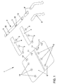
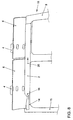
- Fig. 1 is an inventive air supply device 1 in a shown in perspective, the items of the Air supply device 1 are arranged in an exploded view.
- the Air supply device comprises an air duct 2, which over as Connecting piece trained air duct connecting elements 3 with Air distribution channels 4 can be coupled.
- the two air distribution channels 4 are Air outlet nozzles 5 assigned, which in the assembled state of Air supply device 1 on a headliner underside of a headliner. 6 a vehicle interior 7 are arranged facing.
- a Air channel element 9 is provided, in which case two different embodiments the air duct element 9 and 9 'are shown.
- the air channel element 9 ' consists of two Items, so that so depending on, for example, a wheelbase of a Vehicle in which the air supply device 1 is mounted, a simple and flexible coupling of the ventilation source 8 to the air duct 2 by means of Air duct element 9 or 9 'can be produced.
- the headliner 6 can for a simple and inexpensive variant by a flexible plane Be formed wood fiber board, in the recesses on the one hand as Heilausströmerdüse recesses 10 and on the other hand as Dachhimmelaus principle 11, for the Production of a plug-in and sliding connection during assembly of the Air ducts 2 are used, are punched out.
- Connection element recess openings 17 provided in the headliner 6.
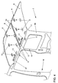
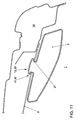
- FIG. 2 the air supply device 1 in the mounted state in a vehicle 13 shown schematically and in perspective.
- the illustrated viewing direction corresponds a view from the vehicle interior 7 obliquely upwards in the direction of a roof spar 14 of the vehicle 13.
- the vehicle 13 is only one Side part 15 shown with the corresponding roof rail 14.
- the air duct element 9 with the not here with is coupled, arranged in the region of the Roof struts 14 is fluidly coupled to the air duct 2.
- the Air duct 2 extends to the headliner underside of the headliner 6 in Vehicle longitudinal direction, wherein the air duct connecting elements 3 through the Terminal element recess openings 17 in the headliner 6 protrude.
- Air duct 2 is laterally in the vehicle 13 in the region of the roof spar 14th arranged so that arranged by the inside of the vehicle interior 7 Air duct 2, the loading height and the headroom of the vehicle interior 7 in the relevant areas, in particular in the area of the vehicle center is restricted.
- the headliner top of the headliner 6 are the two Air distribution channels 4 each in the vehicle transverse direction over the entire vehicle width running arranged, the air distribution channels 4 so on the headliner top are arranged, that the Heilausströmerdüse recesses 10 through the Air distribution channels 4 are covered.
- the Terminal end opposite to the air channel element 9 is a fixing screw 18th provided that a fuse for the air duct 2 in the assembled state in addition to the plug and slide connection between air duct 2 and Roof lining 6 forms.
- Arrows 19 the air flow path in Fig. 2 is located.
- the air flows in Area of the D-pillar 16 through the air channel element 9 vertically upwards and is in Area of the roof rail 14 deflected into the air duct 2.
- the Air duct 2 the air flows in the vehicle longitudinal direction running respectively to the Air duct connection elements 3 and of these in the associated Air distribution channels 4.
- the air distribution ducts 4 Through the air distribution ducts 4, the air flow to the entire Vehicle width distributed and can through the Heilausströmerdüsen 6 in the Vehicle interior 7 flow out.
- FIG. 3 is a schematic sectional view through an air distribution duct 4 shown.
- the air distribution channel 4 has seen in cross section a downwards open hat-shaped profile with mounting flanges 20, wherein the Mounting flanges 20 on the headliner top of the headliner 6 through Bonding and / or fusion and / or tacking and / or welding connected are.
- the headliner top forms a wall portion of the air distribution duct 4, so that the air distribution channel 4 as a simple component, for example by deep drawing can be produced inexpensively.
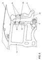
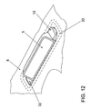
- Fig. 4 is a partial and perspective of the Air supply device 1 shown, only the assembly of the Heilausströmerdüsen 5 on the headliner 6 should be explained.
- the two air distribution channels 4 On the Headliner top of the headliner 6 are the two air distribution channels 4 in Mounted area of the air vent nozzle recesses 10, so that the Luftausströmerdüsen 5 from the vehicle interior 7 in the easy Heilausströmerdüse recesses 10 can be clipped.
- the Heilausströmerdüsen 5 also by a screw connection or by a Gluing to the headliner 6 are mounted.
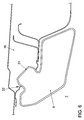
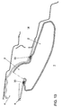
- Fig. 5 is a partial and perspective of the Air supply device 1 shown, in which case the assembly of the air duct element 9th should be shown.
- plastic moldings 21 are arranged, which are assigned to the D-pillar 16 corresponding recesses 22. So can the air channel element 9 simply plugged into the ventilation source 8 accordingly be and also with the plastic moldings 21 in the associated Recesses 22 are clipped to the D-pillar 16.
- arrows 23 is the corresponding assembly sequence in Fig. 5th located.
- Fig. 6 is a schematic sectional view through the air channel element 9 in Area of plastic molding 21 shown in the assembled state. It is too recognize that the plastic molding 21 is formed so that in the assembled Condition behind engaging the plastic molding 21 in the recess 22 takes place. Thus, the air channel element 9 is safe even while driving on the D-pillar 16 held.
- Figs. 9 and 10 is an example of the production of a plug-in and sliding connection explained in detail views.
- the bolt 12 By the during the assembly of the air duct 2 Panning (arrow 25 in Fig. 7) is the bolt 12 in the corresponding associated roof lining 11 inserted.
- the bolt 12 consists of a stud land 27 and a wider compared to the bolt head 28.
- Die Dachhimmelaus originallyung 11 is keyhole-shaped and has a Bolt holder 29 and an adjoining, narrower and of The dimensions forth in approximately the pin web 27 adapted groove-shaped Slot area 30 on.
- Fig. 11 is a schematic sectional view through the air duct 2 in Area of the bolt 12 shown in the assembled state. This is the background of the Bolt head 28 in the slot portion 30 of the headliner recess 11 can be seen.
- the bolt 12 can be spaced from an air duct connection element 3 be performed on the air duct 2. Furthermore, there is the possibility of the Arrange bolt 12 in the region of the air duct connection element 3, as this schematically and in perspective in a view obliquely from above in Fig. 12 is shown.
- the air duct 2 is shown in the assembled state on the headliner 6, so that the bolt head 28, the slot portion 30 of the headliner recess 11, in this embodiment is combined with the connection element recess opening 17, engages behind.
- the air duct connection element 3 Directly adjacent to the bolt 12 is the air duct connection element 3, which passes through the terminal recess opening 17 protrudes and thus a fluid connection between the Air duct 2 and the air distribution duct 4 (not shown here) produces.
- a seal 33 is shown in broken lines in Fig. 12, which is between the Headlining 6 on the headliner side and the air duct 2 circumferentially is arranged around the air duct connection element 3. This will be the Connection area between air duct 2 and air distribution duct 4 sealed, in addition, by the seal 33 a corresponding rattle between the Air duct 2 and the headliner 6 can be guaranteed.
- Fig. 13 is a sectional view through the air duct 2 in FIG Area of an air duct connection element 3 shown in the assembled state.
- the installation position of the seal 33 can be seen, the between the headliner. 6 and the corresponding outer wall portion of the air duct 2 tightly pressed is arranged.
- the seal 33 may be either on the roof sky underside Recess opening edge portion of the terminal recess opening 17 or on the air duct 2 in the region of the air duct connection element 3 to this be pre-assembled all around.
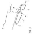
- Fig. 14 is a schematic sectional view through the air duct 2 in Area of the fixing screw 18 shown in the assembled state.
- the fixing screw 18 can be screwed into the roof rail 14.
- the arrangement of the fixing screw 18 on the air duct 2 is advantageously carried out in End portion of the air duct 2, the connection area to the air duct element 9 is opposite (see Fig. 8).
- an air supply device 1 is created in total, consisting of a few and consists inexpensive to produce components.
Landscapes
- Physics & Mathematics (AREA)
- Thermal Sciences (AREA)
- Engineering & Computer Science (AREA)
- Mechanical Engineering (AREA)
- Air-Conditioning For Vehicles (AREA)
- Duct Arrangements (AREA)
Abstract
Description
- Fig. 1
- eine schematische, perspektivische Darstellung einer erfindungsgemäßen Luftversorgungseinrichtung, wobei die Einzelteile in einer Explosionsdarstellung gezeigt sind,
- Fig. 2
- eine schematische, perspektivische Darstellung der Luftversorgungseinrichtung im montierten Zustand,
- Fig. 3
- eine schematische Schnittdarstellung durch einen Luftverteilerkanal,
- Fig. 4
- eine schematische, perspektivische Darstellung eines Teilbereiches der Luftversorgungseinrichtung, wobei die Montage von Luftausströmerdüsen gezeigt ist,
- Fig. 5
- eine schematische, perspektivische Darstellung eines Teilbereichs der Luftversorgungseinrichtung, wobei die Montage eines Luftkanalelements gezeigt ist,
- Fig. 6
- eine schematische Schnittdarstellung durch das Luftkanalelement,
- Fig. 7
- eine schematische Ansicht eines Teilbereichs der Luftversorgungseinrichtung, wobei ein erster Montageschritt zur Anbringung eines Luftführungskanals gezeigt ist,
- Fig.8
- eine schematische Ansicht analog Fig. 7, wobei der zweite Montageschritt zur Anbringung des Luftführungskanals gezeigt ist,
- Fig. 9 und 10
- schematische Detailansichten der Herstellung einer Steck- und Schiebeverbindung des Luftführungskanals an einem Dachhimmel,
- Fig. 11 eine
- schematische Schnittdarstellung durch den Luftführungskanal im montierten Zustand im Bereich der Steck- und Schiebeverbindung,
- Fig. 12
- eine schematische, perspektivische Detaildarstellung eines Luftführungskanal-Anschlusselements im montierten Zustand,
- Fig. 13
- eine schematische Schnittdarstellung durch den Luftführungskanal im Bereich des Luftführungskanal-Anschlusselements im montierten Zustand, und
- Fig. 14
- eine schematische Schnittdarstellung durch den Luftführungskanal im Bereich einer Fixierschraube.
- 1
- Luftversorgungseinrichtung
- 2
- Luftführungskanal
- 3
- Luftführungskanal-Anschlusselement
- 4
- Luftverteilerkanal
- 5
- Luftausströmerdüse
- 6
- Dachhimmel
- 7
- Fahrzeuginnenraum
- 8
- Belüftungsquelle
- 9/9'
- Luftkanalelement
- 10
- Luftausströmerdüse-Ausnehmung
- 11
- Dachhimmelausnehmung
- 12
- Bolzen
- 13
- Fahrzeug
- 14
- Dachholm
- 15
- Seitenteil
- 16
- D-Säule
- 17
- Anschlusselement-Aussparungsöffnung
- 18
- Fixierschraube
- 19
- Pfeil
- 20
- Befestigungsflansch
- 21
- Kunststoff-Ausformung
- 22
- Ausnehmung
- 23
- Pfeil
- 24
- Pfeil
- 25
- Pfeil
- 26
- Pfeil
- 27
- Bolzensteg
- 28
- Bolzenkopf
- 29
- Bolzenaufnahme
- 30
- Schlitzbereich
- 31
- Pfeil
- 32
- Fixiernase
- 33
- Dichtung
Claims (22)
- Luftversorgungseinrichtung zur Klimatisierung eines Fahrzeuginnenraums eines Fahrzeugs, insbesondere eines Nutzfahrzeuges,
mit einem in einem Fahrzeuginnenraum anordenbaren Dachhimmel, auf dessen dem Fahrzeugdach zugeordneter Dachhimmeloberseite wenigstens ein mit einer Belüftungsquelle koppelbarer Luftverteilerkanal angeordnet ist, der sich wenigstens über einen Teilbreich der Dachhimmeloberseite erstreckt und diesen überdeckt wobei im überdeckten Dachhimmeloberseitenbereich als Überdeckungsbereich wenigstens eine Luftausströmerdüse im Dachhimmel für einen Luftdurchtritt in den Fahrzeuginnenraum hinein vorgesehen ist,
dadurch gekennzeichnet, dass die Luftversorgungseinrichtung (1) einen im Fahrzeuginnenraum (7) verlaufenden Luftführungskanal (2) aufweist, der sich im montierten Zustand mit einer Luftführungskanal-Längsseite entlang einer dem Fahrzeuginnenraum (7) zugewandten Dachhimmelunterseite erstreckt, und
dass dieser sich längs entlang der Dachhimmelunterseite erstreckende Luftführungskanal (2) mittelbar oder unmittelbar mit der Belüftungsquelle (8) und mittels wenigstens einem Luftführungskanal-Anschlusselement (3) mittelbar oder unmittelbar mit wenigstens einem Luftverteilerkanal (4) auf der Dachhimmeloberseite gekoppelt ist. - Luftversorgungseinrichtung nach Anspruch 1, dadurch gekennzeichnet, dass das wenigstens eine Luftführungskanal-Anschlusselement (3) durch entsprechende Anschlusselement-Aussparungsöffnungen (17) im Dachhimmel (6) vorzugsweise formschlüssig und/oder dicht hindurchgeführt und mit dem Luftverteilerkanal (4) gekoppelt ist.
- Luftversorgungseinrichtung nach Anspruch 1 oder 2, dadurch gekennzeichnet, dass der Luftführungskanal (2) mittels wenigstens einer als Rast- und/oder als Steck- und/oder Schiebeverbindung ausgebildeten Schnellverbindung am Dachhimmel (6) vorzugsweise lösbar verrastbar und/oder verriegelbar ist.
- Luftversorgungseinrichtung nach Anspruch 3, dadurch gekennzeichnet, dass der Luftführungskanal (2) mittels wenigstens einer Steck- und Schiebeverbindung am Dachhimmel (6) verriegelbar ist dergestalt, dass am Luftführungskanal (2) zur Ausbildung der jeweiligen Steck- und Schiebeverbindung ein Bolzen (12) vorgesehen ist, der einen Bolzensteg (27) und einen demgegenüber breiteren Bolzenkopf (28) aufweist, wobei der Bolzen (12) mit dem Bolzenkopf (28) durch eine dachhimmelseitige Bolzenaufnahme (29) einer schlüssellochartigen Dachhimmelausnehmung (11), an die sich ein gegenüber dem Bolzenkopf (28) schmaler und von den Abmessungen her in etwa an den Bolzensteg (27) angepasster nutenförmiger Schlitzbereich (30) anschließt, steckbar ist, so dass anschließend der Bolzen (12) mit seinem Bolzensteg (27), vorzugsweise mit einem Klemmschluss und/oder mit einem Formschluss, von der Bolzenaufnahme (29) ausgehend in den Schlitzbereich (30) einschiebbar ist und der Bolzenkopf (28) in seiner Verschiebeendposition die Dachhimmelausnehmung (11) im Schlitzbereich (30) hintergreift.
- Luftversorgungseinrichtung nach Anspruch 4, dadurch gekennzeichnet, dass im Bereich des Bolzens (12) ferner wenigstens eine Fixiernase (32) vorgesehen ist, die nach einer Überführung des Bolzens (12) in dessen Verschiebeendposition in den Bereich der Dachhimmelausnehmung, vorzugsweise in den Bereich der Bolzenaufnahme (29), vorzugsweise lösbar einbringbar, vorzugsweise einschiebbar und/oder einschwenkbar ist, dergestalt, dass die Fixiernase (32) im Zusammenwirken mit einem dachhimmelausnehmungsseitigen Gegenelement, vorzugsweise einem Öffnungsrandbereich, ein Verschieben des Bolzens (12) und damit des Luftführungskanales (2) blockiert.
- Luftversorgungseinrichtung nach Anspruch 4 oder 5, dadurch gekennzeichnet, dass die Steck- und Schiebeverbindung an dem Luftführungskanal (2) im Bereich des Luftführungskanal-Anschlusselementes (3) ausgebildet ist.
- Luftversorgungseinrichtung nach einem der Ansprüche 4 bis 6, dadurch gekennzeichnet, dass die Steck- und Schiebeverbindung an einem Außenwandbereich des Luftführungskanals (2) beabstandet von dem wenigstens einen Luftführungskanal-Anschlusselement (3) angeordnet ist.
- Luftversorgungseinrichtung nach einem der Ansprüche 3 bis 7, dadurch gekennzeichnet, dass der Luftführungskanal (2) nach Herstellung der Schnellverbindung mit dem Dachhimmel (6) mittels wenigstens einem Fixierelement (18) am Dachhimmel (6), vorzugsweise im Bereich eines der Belüftungsquelle (8) gegenüberliegenden freien Luftführungskanalendes fixierbar ist.
- Luftversorgungseinrichtung nach einem der Ansprüche 2 bis 8, dadurch gekennzeichnet, dass eine um das Luftführungskanal-Anschlusselement (3) ringförmig herumgeführte Dichtung (33) vorgesehen ist, die im montierten Zustand einerseits an einem dachhimmelunterseitigen Aussparungsöffnungsrandbereich und andererseits an einem entsprechend zugeordneten Luftführungskanalbereich, vorzugsweise einem Außenwandbereich des Luftführungskanals (2) dicht verpresst anliegt.
- Luftversorgungseinrichtung nach einem der Ansprüche 2 bis 9, dadurch gekennzeichnet, dass das wenigstens eine Luftführungskanal-Anschusselement (3) durch einen Anschlussstutzen ausgebildet ist, der vorzugsweise einen rechteckförmigen Querschnitt aufweist.
- Luftversorgungseinrichtung nach einem der Ansprüche 1 bis 10, dadurch gekennzeichnet, dass ein Luftführungskanal (2) vorgesehen ist, der sich im Fahrzeuginnenraum (7) an der Dachhimmelunterseite randseitig im dachholmnahen Bereich (14) in Fahrzeuglängsrichtung erstreckt, vorzugsweise im Fahrzeugfondbereich.
- Luftversorgungseinrichtung nach Anspruch 11, dadurch gekennzeichnet, dass sich der Luftführungskanal (2), vorzugsweise im Fahrzeugfondbereich eines Kombi- oder Nutzfahrzeuges, bis in etwa in den Bereich einer Vertikalsäule, vorzugsweise einer D-Säule (16), erstreckt und mittels einer dort angeordneten Belüftungsquelle (8), vorzugsweise einem Gebläse, gekoppelt ist, gegebenenfalls mittelbar in Abhängigkeit von einem Radstand mittels wenigstens einem sich entlang der Vertikalsäule (16) und/oder einem Dachholmendbereich in Fahrzeuglängsrichtung erstreckenden Luftkanalelement (9; 9') mit der Belüftungsquelle (8) gekoppelt ist.
- Luftversorgungseinrichtung nach Anspruch 12, dadurch gekennzeichnet, dass das die Belüftungsquelle (8) mit dem Luftführungskanal (2) verbindende Luftkanalelement (9; 9') an der Säule (16) mittels wenigstens einer Rast- und/oder Schiebe- und/oder Steckverbindung als Schnellverbindung verrastbar ist, vorzugsweise mittels Ausnehmungen (22) in der Säule (16) hintergreifenden Kunststoff-Ausformungen (21) am Luftkanalelement (9; 9').
- Luftversorgungseinrichtung nach einem der Ansprüche 1 bis 13, dadurch gekennzeichnet, dass sich der auf der Dachhimmeloberseite angeordnete wenigstens eine Luftverteilerkanal (4) über den Dachhimmel (6) zwischen gegenüberliegenden Fahrzeugseiten in Fahrzeugquerrichtung erstreckt, vorzugsweise in einem unverstärktem Fahrzeugdachbereich.
- Luftversorgungseinrichtung nach einem der Ansprüche 2 bis 14, dadurch gekennzeichnet, dass auf der Dachhimmeloberseite wenigstens zwei Luftverteilerkanäle (4) vorgesehen sind, die beabstandet voneinander und in etwa parallel zueinander ausgerichtet sind und in Fahrzeugquerrichtung zwischen gegenüberliegenden Fahrzeugseiten auf der Dachhimmeloberseite verlaufen, und
dass jeder dieser separaten Luftverteilerkanäle (4) mittels einem separaten Luftführungskanal-Anschlusselement (3) mit dem Luftführungskanal (2) strömungsverbunden ist. - Luftversorgungseinrichtung nach einem der Ansprüche 1 bis 15, dadurch gekennzeichnet, dass der Luftverteilerkanal (4) im Querschnitt ein nach unten offenes, vorzugsweise U-förmiges und/oder hutförmiges Profil mit Befestigungsflanschen (20) an den freien Enden aufweist dergestalt, dass der überdeckte Dachhimmeloberseitenbereich Bestandteil der oberseitigen Luftführung ist.
- Luftversorgungseinrichtung nach einem der Ansprüche 1 bis 16, dadurch gekennzeichnet, dass der wenigstens eine Luftverteilerkanal (4) mit der Dachhimmeloberseite durch Kleben und/oder Verschmelzen und/oder Tackern und/oder Schweißen verbunden ist.
- Luftversorgungseinrichtung nach einem der Ansprüche 1 bis 17, dadurch gekennzeichnet, dass der wenigstens eine Luftverteilerkanal (4) aus einem flexiblen, Karton- und/oder Papp- und/oder Holzfaser- und/oder Kunststoffmaterial, vorzugsweise einem Kunststoffschaum, vorzugsweise einem Polyethylen-Schaum hergestellt ist.
- Luftversorgungseinrichtung nach einem der Ansprüche 1 bis 18, dadurch gekennzeichnet, dass der Luftführungskanal (4) und gegebenenfalls damit gekoppelte Luftkanalelemente (9; 9') zum Anschluss an eine Belüftungsquelle (8) einstückig als Kunststoffblasteile, vorzugsweise als genarbte Kunststoffblasteile, vorzugsweise aus Polypropylen, hergestellt ist.
- Luftversorgungseinrichtung nach einem der Ansprüche 1 bis 19, dadurch gekennzeichnet, dass der Dachhimmel (6) als flexible, plane und vorzugsweise dimensionsstabile Platte, vorzugsweise aus einem Kunststoff- und/oder Kartonund/oder Papp- und/oder Holzfasermaterial, hergestellt ist.
- Luftversorgungseinrichtung nach Anspruch 20, dadurch gekennzeichnet, dass die Ausnehmungen (10; 11; 17) für Funktions- und/oder Anbauteile aus dem Dachhimmel (6) ausgestanzt sind.
- Luftversorgungseinrichtung nach Anspruch 20 oder 21, dadurch gekennzeichnet, dass der Dachhimmel (6), vorzugsweise der für den Fondbereich vorgesehene Dachhimmelteil mehrteilig ausgebildet ist.
Applications Claiming Priority (2)
| Application Number | Priority Date | Filing Date | Title |
|---|---|---|---|
| DE10347308A DE10347308A1 (de) | 2003-10-08 | 2003-10-08 | Luftversorgungseinrichtung zur Klimatisierung eines Fahrzeuginnenraums eines Fahrzeugs, insbesondere eines Nutzfahrzeuges |
| DE10347308 | 2003-10-08 |
Publications (2)
| Publication Number | Publication Date |
|---|---|
| EP1522437A1 true EP1522437A1 (de) | 2005-04-13 |
| EP1522437B1 EP1522437B1 (de) | 2006-12-27 |
Family
ID=34306374
Family Applications (1)
| Application Number | Title | Priority Date | Filing Date |
|---|---|---|---|
| EP04021650A Active EP1522437B1 (de) | 2003-10-08 | 2004-09-11 | Luftversorgungseinrichtung zur Klimatisierung eines Fahrzeuginnenraums eines Fahrzeugs, insbesondere eines Nutzfahrzeuges |
Country Status (3)
| Country | Link |
|---|---|
| EP (1) | EP1522437B1 (de) |
| AT (1) | ATE349346T1 (de) |
| DE (2) | DE10347308A1 (de) |
Cited By (2)
| Publication number | Priority date | Publication date | Assignee | Title |
|---|---|---|---|---|
| DE102008024430A1 (de) | 2008-05-20 | 2009-11-26 | Dr. Ing. H.C. F. Porsche Aktiengesellschaft | Kraftfahrzeug mit Luftkanalabschnitten für die Klimatisierung des Fahrzeuginnenraums |
| JP2016222022A (ja) * | 2015-05-27 | 2016-12-28 | ヤンマー株式会社 | 作業車 |
Families Citing this family (5)
| Publication number | Priority date | Publication date | Assignee | Title |
|---|---|---|---|---|
| DE102005031875B4 (de) * | 2005-07-07 | 2013-05-29 | Webasto Ag | Dachmodul mit Belüftungskanal |
| DE102008013450B4 (de) | 2008-03-10 | 2023-08-03 | Volkswagen Ag | Fahrgastraumklimatisierung in einem Fahrzeug und Wärmeaustauscher-Einrichtung dafür |
| DE102016205254B4 (de) * | 2016-03-30 | 2018-11-15 | Volkswagen Aktiengesellschaft | Luftführungseinrichtung, bodenseitiges Luftführungssystem und Kraftfahrzeug |
| DE102018222502A1 (de) * | 2018-12-20 | 2020-06-25 | Continental Engineering Services Gmbh | Belüftungssystem für eine lokal anpassbare Temperaturzone in einem Fahrgastraum |
| DE102020208217A1 (de) | 2020-07-01 | 2022-01-05 | Volkswagen Aktiengesellschaft | Fahrzeug mit einer Luftversorgungseinrichtung |
Citations (3)
| Publication number | Priority date | Publication date | Assignee | Title |
|---|---|---|---|---|
| US4640184A (en) * | 1984-05-07 | 1987-02-03 | Toyota Jidosha Kabushiki Kaisha | Mounting structure for a roof duct |
| EP0962342A2 (de) * | 1998-06-03 | 1999-12-08 | Ohtsuka Co., Ltd. | Stossenergieaufnehmende Luftzufuhrleitung |
| DE10058366A1 (de) * | 1999-11-26 | 2001-06-13 | Honda Motor Co Ltd | Luftleit- und Verkleidungsstruktur für ein Automobil |
Family Cites Families (6)
| Publication number | Priority date | Publication date | Assignee | Title |
|---|---|---|---|---|
| JPS5815204Y2 (ja) * | 1978-04-11 | 1983-03-28 | 日産自動車株式会社 | 車両用空気吹出し装置 |
| US4893866A (en) * | 1988-06-10 | 1990-01-16 | United Technologies Automotive Inc. | Motor vehicle body structure for receiving snap-fit modular headliner fasteners |
| DE4237344C2 (de) * | 1992-11-05 | 1996-09-19 | Beneform Gmbh | Autohimmel für die Dachinnenverkleidung eines Personenkraftfahrzeugs oder Kleinbusses |
| US6062635A (en) * | 1998-03-20 | 2000-05-16 | Lear Automotive Dearborn, Inc, | Plastic air duct integrated to headliner |
| DE19832738A1 (de) * | 1998-07-21 | 2000-01-27 | Christian P Rassaerts | Fahrgastzelle für ein Transportfahrzeug |
| US20030164219A1 (en) * | 2002-02-20 | 2003-09-04 | Joerg Brahm | Headliner/duct assembly and welding process therefor |
-
2003
- 2003-10-08 DE DE10347308A patent/DE10347308A1/de not_active Withdrawn
-
2004
- 2004-09-11 EP EP04021650A patent/EP1522437B1/de active Active
- 2004-09-11 AT AT04021650T patent/ATE349346T1/de not_active IP Right Cessation
- 2004-09-11 DE DE502004002426T patent/DE502004002426D1/de active Active
Patent Citations (3)
| Publication number | Priority date | Publication date | Assignee | Title |
|---|---|---|---|---|
| US4640184A (en) * | 1984-05-07 | 1987-02-03 | Toyota Jidosha Kabushiki Kaisha | Mounting structure for a roof duct |
| EP0962342A2 (de) * | 1998-06-03 | 1999-12-08 | Ohtsuka Co., Ltd. | Stossenergieaufnehmende Luftzufuhrleitung |
| DE10058366A1 (de) * | 1999-11-26 | 2001-06-13 | Honda Motor Co Ltd | Luftleit- und Verkleidungsstruktur für ein Automobil |
Cited By (5)
| Publication number | Priority date | Publication date | Assignee | Title |
|---|---|---|---|---|
| DE102008024430A1 (de) | 2008-05-20 | 2009-11-26 | Dr. Ing. H.C. F. Porsche Aktiengesellschaft | Kraftfahrzeug mit Luftkanalabschnitten für die Klimatisierung des Fahrzeuginnenraums |
| CN101585309B (zh) * | 2008-05-20 | 2013-03-27 | F.波尔希名誉工学博士公司 | 具有用于汽车内室空气调节的气道段的汽车 |
| DE102008024430B4 (de) * | 2008-05-20 | 2017-03-02 | Dr. Ing. H.C. F. Porsche Aktiengesellschaft | Kraftfahrzeug mit Luftkanalabschnitten für die Klimatisierung des Fahrzeuginnenraums |
| US9694648B2 (en) | 2008-05-20 | 2017-07-04 | Dr. Ing, H.C.F. Porsche Aktiengesellschaft | Motor vehicle with air duct sections for the air conditioning of the vehicle interior space |
| JP2016222022A (ja) * | 2015-05-27 | 2016-12-28 | ヤンマー株式会社 | 作業車 |
Also Published As
| Publication number | Publication date |
|---|---|
| DE502004002426D1 (de) | 2007-02-08 |
| DE10347308A1 (de) | 2005-05-04 |
| EP1522437B1 (de) | 2006-12-27 |
| ATE349346T1 (de) | 2007-01-15 |
Similar Documents
| Publication | Publication Date | Title |
|---|---|---|
| DE102005031875B4 (de) | Dachmodul mit Belüftungskanal | |
| EP0964814B1 (de) | Fahrzeugdach und verfahren zur montage des fahrzeugdachs an einer karosserie | |
| EP1532040B1 (de) | Kraftwagen-karosserie mit einer tragstruktur aus grossformatigen teilmodulen | |
| DE102007036918B4 (de) | Instrumententräger | |
| EP0808736A2 (de) | Instrumententafel für ein Kraftfahrzeug | |
| WO2007140892A1 (de) | Stossfängermodul | |
| DE102011009605B4 (de) | Anordnung einer Instrumententafel im Innenraum eines Kraftfahrzeuges | |
| EP2230159B1 (de) | Verkleidungsteil in einem Kotflügel eines Kraftfahrzeugs mit strömungstechnischer Verbindung zu einer Scheinwerfereinheit | |
| EP1265777B1 (de) | Strukturelement zur montage an einer fahrzeugstruktur | |
| WO2007124912A1 (de) | Kraftwagenheck sowie zugehörige heckleuchte | |
| EP1522437B1 (de) | Luftversorgungseinrichtung zur Klimatisierung eines Fahrzeuginnenraums eines Fahrzeugs, insbesondere eines Nutzfahrzeuges | |
| DE10146694A1 (de) | Verkleidungselement für das Dach eines Fahrzeuginnenraums | |
| EP1291266B1 (de) | Hybridträger für ein Kraftfahrzeug | |
| EP1562820A1 (de) | Baugruppe für ein cockpit-bereich | |
| DE102018101490A1 (de) | Strukturelle luftleitung für fahrzeuge | |
| DE10062151B4 (de) | Instrumententafel, insbesondere für ein Kraftfahrzeug, mit einem Grundkörper und einer Abdeckung | |
| DE102013013363A1 (de) | Halteanordnung einer Instrumententafel an einem Querträger für einen Kraftwagen | |
| EP2615014B1 (de) | Verfahren zum Herstellen eines Fahrerhauses für ein Kraftfahrzeug | |
| EP3424805B1 (de) | Kabine für ein landwirtschaftliches arbeitsfahrzeug | |
| DE102007029859A1 (de) | Pkw-Rohkarosserie | |
| DE10347309B4 (de) | Luftversorgungseinrichtung zur Klimatisierung eines Fahrzeuginneraums eines Fahrzeugs, insbesondere eines Nutzfahrzeuges | |
| EP2799265B1 (de) | Türrahmenmodul für eine modular aufgebaute Kraftfahrzeugtür und modular aufgebaute Kraftfahrzeugtür mit einem solchen Türrahmenmodul | |
| DE10347847B3 (de) | Kraftwagenkarosserie mit zentraler Tragsäule | |
| EP0891892B1 (de) | Aus thermoplastischem Kunststoff im Blasverfahren hergestellte Türverkleidung für Kraftfahrzeuge | |
| DE19948223B4 (de) | Fahrgastzelle eines Fahrzeugs |
Legal Events
| Date | Code | Title | Description |
|---|---|---|---|
| PUAI | Public reference made under article 153(3) epc to a published international application that has entered the european phase |
Free format text: ORIGINAL CODE: 0009012 |
|
| AK | Designated contracting states |
Kind code of ref document: A1 Designated state(s): AT BE BG CH CY CZ DE DK EE ES FI FR GB GR HU IE IT LI LU MC NL PL PT RO SE SI SK TR |
|
| AX | Request for extension of the european patent |
Extension state: AL HR LT LV MK |
|
| 17P | Request for examination filed |
Effective date: 20051013 |
|
| AKX | Designation fees paid |
Designated state(s): AT BE BG CH CY CZ DE DK EE ES FI FR GB GR HU IE IT LI LU MC NL PL PT RO SE SI SK TR |
|
| GRAP | Despatch of communication of intention to grant a patent |
Free format text: ORIGINAL CODE: EPIDOSNIGR1 |
|
| GRAS | Grant fee paid |
Free format text: ORIGINAL CODE: EPIDOSNIGR3 |
|
| GRAA | (expected) grant |
Free format text: ORIGINAL CODE: 0009210 |
|
| AK | Designated contracting states |
Kind code of ref document: B1 Designated state(s): AT BE BG CH CY CZ DE DK EE ES FI FR GB GR HU IE IT LI LU MC NL PL PT RO SE SI SK TR |
|
| PG25 | Lapsed in a contracting state [announced via postgrant information from national office to epo] |
Ref country code: IT Free format text: LAPSE BECAUSE OF FAILURE TO SUBMIT A TRANSLATION OF THE DESCRIPTION OR TO PAY THE FEE WITHIN THE PRESCRIBED TIME-LIMIT;WARNING: LAPSES OF ITALIAN PATENTS WITH EFFECTIVE DATE BEFORE 2007 MAY HAVE OCCURRED AT ANY TIME BEFORE 2007. THE CORRECT EFFECTIVE DATE MAY BE DIFFERENT FROM THE ONE RECORDED. Effective date: 20061227 Ref country code: NL Free format text: LAPSE BECAUSE OF FAILURE TO SUBMIT A TRANSLATION OF THE DESCRIPTION OR TO PAY THE FEE WITHIN THE PRESCRIBED TIME-LIMIT Effective date: 20061227 Ref country code: SK Free format text: LAPSE BECAUSE OF FAILURE TO SUBMIT A TRANSLATION OF THE DESCRIPTION OR TO PAY THE FEE WITHIN THE PRESCRIBED TIME-LIMIT Effective date: 20061227 Ref country code: SI Free format text: LAPSE BECAUSE OF FAILURE TO SUBMIT A TRANSLATION OF THE DESCRIPTION OR TO PAY THE FEE WITHIN THE PRESCRIBED TIME-LIMIT Effective date: 20061227 Ref country code: FI Free format text: LAPSE BECAUSE OF FAILURE TO SUBMIT A TRANSLATION OF THE DESCRIPTION OR TO PAY THE FEE WITHIN THE PRESCRIBED TIME-LIMIT Effective date: 20061227 Ref country code: RO Free format text: LAPSE BECAUSE OF FAILURE TO SUBMIT A TRANSLATION OF THE DESCRIPTION OR TO PAY THE FEE WITHIN THE PRESCRIBED TIME-LIMIT Effective date: 20061227 Ref country code: CZ Free format text: LAPSE BECAUSE OF FAILURE TO SUBMIT A TRANSLATION OF THE DESCRIPTION OR TO PAY THE FEE WITHIN THE PRESCRIBED TIME-LIMIT Effective date: 20061227 Ref country code: DK Free format text: LAPSE BECAUSE OF FAILURE TO SUBMIT A TRANSLATION OF THE DESCRIPTION OR TO PAY THE FEE WITHIN THE PRESCRIBED TIME-LIMIT Effective date: 20061227 Ref country code: PL Free format text: LAPSE BECAUSE OF FAILURE TO SUBMIT A TRANSLATION OF THE DESCRIPTION OR TO PAY THE FEE WITHIN THE PRESCRIBED TIME-LIMIT Effective date: 20061227 Ref country code: IE Free format text: LAPSE BECAUSE OF FAILURE TO SUBMIT A TRANSLATION OF THE DESCRIPTION OR TO PAY THE FEE WITHIN THE PRESCRIBED TIME-LIMIT Effective date: 20061227 |
|
| REG | Reference to a national code |
Ref country code: GB Ref legal event code: FG4D Free format text: NOT ENGLISH |
|
| REG | Reference to a national code |
Ref country code: IE Ref legal event code: FG4D Free format text: LANGUAGE OF EP DOCUMENT: GERMAN |
|
| REF | Corresponds to: |
Ref document number: 502004002426 Country of ref document: DE Date of ref document: 20070208 Kind code of ref document: P |
|
| PG25 | Lapsed in a contracting state [announced via postgrant information from national office to epo] |
Ref country code: SE Free format text: LAPSE BECAUSE OF FAILURE TO SUBMIT A TRANSLATION OF THE DESCRIPTION OR TO PAY THE FEE WITHIN THE PRESCRIBED TIME-LIMIT Effective date: 20070327 Ref country code: BG Free format text: LAPSE BECAUSE OF FAILURE TO SUBMIT A TRANSLATION OF THE DESCRIPTION OR TO PAY THE FEE WITHIN THE PRESCRIBED TIME-LIMIT Effective date: 20070327 |
|
| PG25 | Lapsed in a contracting state [announced via postgrant information from national office to epo] |
Ref country code: ES Free format text: LAPSE BECAUSE OF FAILURE TO SUBMIT A TRANSLATION OF THE DESCRIPTION OR TO PAY THE FEE WITHIN THE PRESCRIBED TIME-LIMIT Effective date: 20070407 |
|
| PG25 | Lapsed in a contracting state [announced via postgrant information from national office to epo] |
Ref country code: PT Free format text: LAPSE BECAUSE OF FAILURE TO SUBMIT A TRANSLATION OF THE DESCRIPTION OR TO PAY THE FEE WITHIN THE PRESCRIBED TIME-LIMIT Effective date: 20070528 |
|
| NLV1 | Nl: lapsed or annulled due to failure to fulfill the requirements of art. 29p and 29m of the patents act | ||
| GBV | Gb: ep patent (uk) treated as always having been void in accordance with gb section 77(7)/1977 [no translation filed] |
Effective date: 20061227 |
|
| EN | Fr: translation not filed | ||
| REG | Reference to a national code |
Ref country code: IE Ref legal event code: FD4D |
|
| PLBE | No opposition filed within time limit |
Free format text: ORIGINAL CODE: 0009261 |
|
| STAA | Information on the status of an ep patent application or granted ep patent |
Free format text: STATUS: NO OPPOSITION FILED WITHIN TIME LIMIT |
|
| PG25 | Lapsed in a contracting state [announced via postgrant information from national office to epo] |
Ref country code: GB Free format text: LAPSE BECAUSE OF FAILURE TO SUBMIT A TRANSLATION OF THE DESCRIPTION OR TO PAY THE FEE WITHIN THE PRESCRIBED TIME-LIMIT Effective date: 20061227 |
|
| 26N | No opposition filed |
Effective date: 20070928 |
|
| BERE | Be: lapsed |
Owner name: VOLKSWAGEN AG Effective date: 20070930 |
|
| PG25 | Lapsed in a contracting state [announced via postgrant information from national office to epo] |
Ref country code: MC Free format text: LAPSE BECAUSE OF NON-PAYMENT OF DUE FEES Effective date: 20070930 Ref country code: FR Free format text: LAPSE BECAUSE OF FAILURE TO SUBMIT A TRANSLATION OF THE DESCRIPTION OR TO PAY THE FEE WITHIN THE PRESCRIBED TIME-LIMIT Effective date: 20070817 Ref country code: GR Free format text: LAPSE BECAUSE OF FAILURE TO SUBMIT A TRANSLATION OF THE DESCRIPTION OR TO PAY THE FEE WITHIN THE PRESCRIBED TIME-LIMIT Effective date: 20070328 |
|
| PG25 | Lapsed in a contracting state [announced via postgrant information from national office to epo] |
Ref country code: BE Free format text: LAPSE BECAUSE OF NON-PAYMENT OF DUE FEES Effective date: 20070930 |
|
| PG25 | Lapsed in a contracting state [announced via postgrant information from national office to epo] |
Ref country code: FR Free format text: LAPSE BECAUSE OF FAILURE TO SUBMIT A TRANSLATION OF THE DESCRIPTION OR TO PAY THE FEE WITHIN THE PRESCRIBED TIME-LIMIT Effective date: 20061227 Ref country code: AT Free format text: LAPSE BECAUSE OF NON-PAYMENT OF DUE FEES Effective date: 20070911 |
|
| PG25 | Lapsed in a contracting state [announced via postgrant information from national office to epo] |
Ref country code: EE Free format text: LAPSE BECAUSE OF FAILURE TO SUBMIT A TRANSLATION OF THE DESCRIPTION OR TO PAY THE FEE WITHIN THE PRESCRIBED TIME-LIMIT Effective date: 20061227 |
|
| REG | Reference to a national code |
Ref country code: CH Ref legal event code: PL |
|
| PG25 | Lapsed in a contracting state [announced via postgrant information from national office to epo] |
Ref country code: LI Free format text: LAPSE BECAUSE OF NON-PAYMENT OF DUE FEES Effective date: 20070930 Ref country code: CH Free format text: LAPSE BECAUSE OF NON-PAYMENT OF DUE FEES Effective date: 20070930 |
|
| PG25 | Lapsed in a contracting state [announced via postgrant information from national office to epo] |
Ref country code: LU Free format text: LAPSE BECAUSE OF NON-PAYMENT OF DUE FEES Effective date: 20070911 Ref country code: CY Free format text: LAPSE BECAUSE OF FAILURE TO SUBMIT A TRANSLATION OF THE DESCRIPTION OR TO PAY THE FEE WITHIN THE PRESCRIBED TIME-LIMIT Effective date: 20061227 |
|
| PG25 | Lapsed in a contracting state [announced via postgrant information from national office to epo] |
Ref country code: HU Free format text: LAPSE BECAUSE OF FAILURE TO SUBMIT A TRANSLATION OF THE DESCRIPTION OR TO PAY THE FEE WITHIN THE PRESCRIBED TIME-LIMIT Effective date: 20070628 Ref country code: TR Free format text: LAPSE BECAUSE OF FAILURE TO SUBMIT A TRANSLATION OF THE DESCRIPTION OR TO PAY THE FEE WITHIN THE PRESCRIBED TIME-LIMIT Effective date: 20061227 |
|
| PG25 | Lapsed in a contracting state [announced via postgrant information from national office to epo] |
Ref country code: LI Free format text: LAPSE BECAUSE OF NON-PAYMENT OF DUE FEES Effective date: 20080930 Ref country code: CH Free format text: LAPSE BECAUSE OF NON-PAYMENT OF DUE FEES Effective date: 20080930 |
|
| REG | Reference to a national code |
Ref country code: DE Ref legal event code: R084 Ref document number: 502004002426 Country of ref document: DE |
|
| REG | Reference to a national code |
Ref country code: DE Ref legal event code: R085 Ref document number: 502004002426 Country of ref document: DE |
|
| P01 | Opt-out of the competence of the unified patent court (upc) registered |
Effective date: 20230523 |
|
| PGFP | Annual fee paid to national office [announced via postgrant information from national office to epo] |
Ref country code: DE Payment date: 20230930 Year of fee payment: 20 |