EP1522388A1 - Kassette für einen bürohefter - Google Patents
Kassette für einen bürohefter Download PDFInfo
- Publication number
- EP1522388A1 EP1522388A1 EP03730677A EP03730677A EP1522388A1 EP 1522388 A1 EP1522388 A1 EP 1522388A1 EP 03730677 A EP03730677 A EP 03730677A EP 03730677 A EP03730677 A EP 03730677A EP 1522388 A1 EP1522388 A1 EP 1522388A1
- Authority
- EP
- European Patent Office
- Prior art keywords
- staple
- staples
- cassette
- feeder
- stapler
- Prior art date
- Legal status (The legal status is an assumption and is not a legal conclusion. Google has not performed a legal analysis and makes no representation as to the accuracy of the status listed.)
- Withdrawn
Links
Images




Classifications
-
- B—PERFORMING OPERATIONS; TRANSPORTING
- B25—HAND TOOLS; PORTABLE POWER-DRIVEN TOOLS; MANIPULATORS
- B25C—HAND-HELD NAILING OR STAPLING TOOLS; MANUALLY OPERATED PORTABLE STAPLING TOOLS
- B25C5/00—Manually operated portable stapling tools; Hand-held power-operated stapling tools; Staple feeding devices therefor
- B25C5/16—Staple-feeding devices, e.g. with feeding means, supports for staples or accessories concerning feeding devices
- B25C5/1606—Feeding means
- B25C5/1617—Feeding means employing a spring-loaded pusher
-
- B—PERFORMING OPERATIONS; TRANSPORTING
- B25—HAND TOOLS; PORTABLE POWER-DRIVEN TOOLS; MANIPULATORS
- B25C—HAND-HELD NAILING OR STAPLING TOOLS; MANUALLY OPERATED PORTABLE STAPLING TOOLS
- B25C5/00—Manually operated portable stapling tools; Hand-held power-operated stapling tools; Staple feeding devices therefor
- B25C5/02—Manually operated portable stapling tools; Hand-held power-operated stapling tools; Staple feeding devices therefor with provision for bending the ends of the staples on to the work
- B25C5/0221—Stapling tools of the table model type, i.e. tools supported by a table or the work during operation
- B25C5/0242—Stapling tools of the table model type, i.e. tools supported by a table or the work during operation having a pivoting upper leg and a leg provided with an anvil supported by the table or work
- B25C5/025—Stapling tools of the table model type, i.e. tools supported by a table or the work during operation having a pivoting upper leg and a leg provided with an anvil supported by the table or work the plunger being manually operated
-
- B—PERFORMING OPERATIONS; TRANSPORTING
- B25—HAND TOOLS; PORTABLE POWER-DRIVEN TOOLS; MANIPULATORS
- B25C—HAND-HELD NAILING OR STAPLING TOOLS; MANUALLY OPERATED PORTABLE STAPLING TOOLS
- B25C5/00—Manually operated portable stapling tools; Hand-held power-operated stapling tools; Staple feeding devices therefor
- B25C5/16—Staple-feeding devices, e.g. with feeding means, supports for staples or accessories concerning feeding devices
-
- B—PERFORMING OPERATIONS; TRANSPORTING
- B25—HAND TOOLS; PORTABLE POWER-DRIVEN TOOLS; MANIPULATORS
- B25C—HAND-HELD NAILING OR STAPLING TOOLS; MANUALLY OPERATED PORTABLE STAPLING TOOLS
- B25C5/00—Manually operated portable stapling tools; Hand-held power-operated stapling tools; Staple feeding devices therefor
- B25C5/16—Staple-feeding devices, e.g. with feeding means, supports for staples or accessories concerning feeding devices
- B25C5/1637—Supports for the staples being fed
- B25C5/1641—Supports for the staples being fed allowing the feeding of a variety of elements
- B25C5/1658—Supports for the staples being fed allowing the feeding of a variety of elements of different sizes of staples
Definitions
- the present invention relates to a cassette for a stapler, which can be stored with staples having needle legs of different lengths.
- a stapler cassette has been proposed by us in JP-KOKAI(unexamined patent publication)-HEI07-96475.
- a frame 32 is provided at its leading end with a cap 33, and accommodates a guide 34 loaded with staples 35.
- a pusher head 37 which is attached to the leading end of a pusher spring 36 so as to slide the rear end of the staples 35 back and forth.
- the staples 35 are pushed at all times toward the cap 33 by the pusher head 37.
- Numeral 38 designates a rear end cap of the pusher spring 36.
- the staples 35 stored in the stapler cassette are extruded down by the downward push of the cap 33.
- cassettes of the prior art are insufficient for storing the staples and are encountered by the phenomenon of staple clogging and by the deficient stability of products.
- the invention has been conceived in view of the problems of the prior art thus far described, and has an obj ect to provide a cassette, which can store the staples having the different needle leg lengths without increasing the kinds of the cassette and which can be manufactured at a low cost.
- a cassette for a stapler stored with a multiplicity of juxtaposed staples each having a pair of opposed needle legs comprising: a cassette body formed slender with a channel-shaped cross section and having a staple guide slit opened in the upper face thereof, through which the blade for extruding staples stored on the upper face of the leading end portion is moved up and down; a staple holder fitted in the channel-shaped open face of the cassette body and having a staple extrusion groove opened below the blade guide slit of the cassette body and at a position to confront the blade guide slit and having a pair of erected guide walls supporting the needle legs; a feeder pushing the staples toward the staple extrusion groove of the staple holder; a spring for urging the feeder toward the stapler extrusion groove of the staple holder; and a guide rod for guiding the movement of the feeder.
- the cassette is characterized in that the staples are extruded,
- the stapler cassette according to Claim 2 is characterized in that a pair of guide walls for supporting the leading ends of the needle legs are erected along the side edge portions of the staple holder.
- the stapler cassette according to Claim 3 is characterized in that retaining projections for fixing the loading position of the cassette stored with the staples are formed on the upper face of the rear portion of the cassette body and/or on the lower face of the rear portion of the staple holder.
- the stapler cassette according to Claim 4 is characterized in that the cassette is made of a hard synthetic resin.
- the stapler cassette of the invention is constructed such that the staple holder is separately incorporated into the cassette body.
- the staple holder provided with the guide walls having a height corresponding to the length of the needle legs, therefore, the cassette can be efficiently used without any change in its entirety while meeting the demand for the staples of different needle leg lengths.
- the paired confronting guide walls act as rails to mount the needle legs of the staples thereon. Therefore, the staples are carried on the ceiling portion so that they are not encountered by any rattling. Moreover, the guide walls have no clearance from the ceiling portion of the staples so that they guide the staples to the staple extrusion groove. Therefore, neither rattling nor clogging occurs in the staples being carried.
- the retaining projections are formed on the upper face of the rear portion of the cassette body and/or on the lower face of the rear portion of the staple holder. As a result, the cassette can be loaded no matter whether the stapler-side retained portion might be positioned on the upper or lower side.
- the cassette is made of plastics at a low cost so that it can be disposed of.
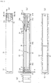
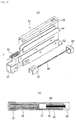
- Fig. 1 presents explanatory side elevations of the state, in which a cassette for a stapler according to the invention is inserted into a stapler body
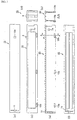
- Fig. 2 presents explanatory views showing the state, in which the stapler cassette according to a first embodiment of the invention is partially cut away
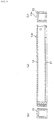
- Fig. 3 presents explanatory views of a cassette body of Fig. 2
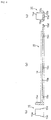
- Fig. 4 also presents explanatory views of a staple holder shown in Fig. 2
- Fig. 5 presents explanatory views of a staple holder shown in Fig. 2
- Fig. 6 presents explanatory sections of a staple holder of a stapler cassette according to a second embodiment of the invention
- FIG. 7 presents sections showing the sides, on which the staple holder having guide walls formed, as shown in Fig. 6, is incorporated into a cassette body;
- Fig. 8 presents enlarged sections showing the sides, on which staples shown in the first embodiment are loaded into the cassette; and
- Fig. 9 presents enlarged sections showing the sides, on which staples shown in the second embodiment are loaded into the cassette.
- a stapler cassette 1 As shown in Fig. 1 (a) and (b), staples 4 are loaded into a stapler body 2 of a cassette type stapler to be driven downward.
- the stapler body 2 is constructed to include integrally a frame 5 having an insertion hole for fitting the cassette 1, and a cover portion 7 supported by the frame 5 with a guide portion 6.
- the handle 8 is biased upward by bias means such as a spring to turn on the (not-shown) pin below the rear end of the cassette guide portion 6, and is disposed over the frame 5.
- reference numeral 9 designates a take-out lever disposedat the rear end of the cover 7 for extracting the cassette 1
- numeral 10 designates a base for the stapler body 2 of the cassette type stapler.
- the blade 3 is driven downward in association with the handle 8 so that it can shoot the staples 4 down onto the base 10.
- the lever 9 disposed at the back of the cover portion 7 is pushed downward, and the cassette 1 retained automatically by retaining projections is then released from the retention.
- the cassette 1 is projected forward so that it can be replaced.
- the cassette 1 is constructed to comprise: a cassette body 13 formed slender with a channel-shaped cross section and having a blade guide slit 11 opened in the upper face thereof, through which the blade 3 for extruding the staples 4 stored on the upper face of the leading end portion is moved up and down; a staple holder 15 fitted in the channel-shaped open face of the cassette body 13 and having a staple extrusion groove 12 opened below the blade guide slit 11 of the cassette body 13 and at a position to confront the staple guide slit 11; a feeder 16 pushing the staples 4 toward the staple extrusion groove 12 of the staple holder 15; a spring 17 for urging the feeder 16 toward the stapler extrusion groove 12 of the staple holder 15; and a guide rod 18 for guiding the movement of the feeder 16.
- the staplers 4 are pushed from the stapler extrusion groove 12 onto the base 10 by- the vertical movements of the blade 3.
- the cassette body 13 is provided with a retaining projection 15a on the upper face of the rear portion for fixing the loading position when the cassette body 13 is loaded with the staples 4, and retaining holes 13b at three longitudinal portions on the two side faces for retaining the staple holder 15.
- the cassette body 13 has an internal width set to accommodate the external width of the staples 4 slidably.
- the staple holder 15 to be incorporated into the cassette body 13 is formed, as shown in Fig. 2(a), to include a guide head 20 having a width to guide the internal width of the staples 4 slidably, and a longitudinal base plate 21 leading to the rear end of the cassettebody 13.
- the base plate 21 is provided at three longitudinal portions on its side faces with retaining projections 15c to be fitted in the sides of the cassette body 13.
- the base plate 21 is further provided on the lower face of its rear end with a retaining projection 21b for fixing the loading position when the staple holder is loaded into the stapler 2.
- the feeder 16 for pushing the staples 4 toward the leading end of the cassette 1 is provided on its front face with a pushing end face 16a which is shaped to correspond to the channel shape of the staples 4, and on its rear face with a spring seat 16b for receiving the abutment of the spring 17.
- a hole 16c In the center of the spring seat 16b, moreover, there is formed a hole 16c, through which the guide rod 18 can slidably move.
- the guide rod 18 has a length from the leading end of the staple 4 on the side of the staple extrusion groove 12 to the rear end.
- the guide rod 18 has a fixing end portion 18a formed integrally with its rear end, and is fixed in retaining recesses 18c on the cassette body-side, as shown in Fig. 1(b), through retaining projections 18b formed on the two sides of the fixing end portion 18a.
- the feeder 16 is mounted on the guide rod 18, and the spring 17 is interposed between the feeder 16 and the fixing end portion 18a.
- a cassette 1 is constructed to comprise: the cassette body 13 formed slender with the channel-shaped cross section and having the staple guide slit 11 opened in the upper face thereof, through which the blade 3 for extruding the staples 4 stored on the upper face of the leading end portion is moved up and down; the staple holder 15 fitted in the channel-shaped open face of the cassette body 13, having the staple extrusion groove 12 opened below the blade guide slit 11 of the cassette body 13 and at a position to confront the staple guide slit 11, and a pair of guide walls 14 erected along the side edges thereof for supporting the needle legs of the staples 4; the feeder 16 pushing the staples 4 on the guide walls 14 toward the staple extrusion groove 12 of the staple holder 15; the spring 17 for urging the feeder 16 toward the staple extrusion groove 12 of the staple holder 15; and the guide rod 18 for guiding the movement of the feeder 16.
- the staples 4 on the guide walls 14 are pushed from the staple extrusion groove 12 onto the base 10 by the vertical movements of the blade 3.
- This embodiment is characterized, as shown in Fig. 4 to Fig. 5, in that the guide walls 14 are so formed in the longitudinal direction on the two sides of the upper face of the base plate 21 as to have various heights corresponding to the needle lengths of the staples 4. As shown in Fig. 9, the guide walls 14 are divided into guide walls 14a, 14b and 14c corresponding to the staples 4 having the largest needle length. By changing the heights of the guide walls 14, therefore, the guide walls 14 can hold and accommodate the various staples 4 having the different needle lengths at a predetermined height.
- the cassette thus constructed is wholly made of plastics excepting the spring for pushing the staples.
- the staple holder 15 which is provided with the guide walls 14 having the heights corresponding to the needle lengths of the staples 4, is loaded into the cassette body 13 so that the edges of the staples 4 are held on the guide walls 14.
- the staples 4 are held at the predetermined height so that the staples 4 on the guide walls 14 take positions contacting with the upper face of the cassette body 13, as shown at (b) in Fig. 8 to Fig. 12.
- the relative positions between the upper end of the staples 4 and the lower end of the blade 3 become identical independently of the needle lengths so that the staples 4 can be shot under the identical conditions.
- the staples are supported on the inner wall faces of the cassette body 13, and the rattling at the feeding time is prevented by the guide head 20.
- the blade can be smoothly actuated.
- the cassette can store the staples having the different needle leg lengths without increasing the kinds of the cassette and can be manufactured at a low cost.
- the staple holder having the guide walls with the heights corresponding to the needle lengths is separately incorporated into the cassette body so that the cassette can be wholly accommodated without any change even with the different needle lengths of the staples.
- the guide walls confronting each other act as rails to carry the staples on the ceiling portion so that they guide the staples without any rattling.
- the staples move without any rattling to cause no staple clogging.
- the retaining projections for fitting the staples are provided on the two upper and lower faces so that the cassette can be loaded no matter whether it might be directed to have the stapler-side retained portion on the upper or lower side.
- the cassette is made of plastics at the low cost so that it can be disposed of.
Landscapes
- Engineering & Computer Science (AREA)
- Mechanical Engineering (AREA)
- Portable Nailing Machines And Staplers (AREA)
Applications Claiming Priority (3)
| Application Number | Priority Date | Filing Date | Title |
|---|---|---|---|
| JP2002154343 | 2002-05-28 | ||
| JP2002154343 | 2002-05-28 | ||
| PCT/JP2003/006708 WO2003099521A1 (en) | 2002-05-28 | 2003-05-28 | Cassette for stapler |
Publications (2)
| Publication Number | Publication Date |
|---|---|
| EP1522388A1 true EP1522388A1 (de) | 2005-04-13 |
| EP1522388A4 EP1522388A4 (de) | 2008-02-13 |
Family
ID=29561353
Family Applications (1)
| Application Number | Title | Priority Date | Filing Date |
|---|---|---|---|
| EP03730677A Withdrawn EP1522388A4 (de) | 2002-05-28 | 2003-05-28 | Kassette für einen bürohefter |
Country Status (6)
| Country | Link |
|---|---|
| US (1) | US7066370B2 (de) |
| EP (1) | EP1522388A4 (de) |
| JP (1) | JP4295720B2 (de) |
| CN (1) | CN100377844C (de) |
| AU (1) | AU2003241863A1 (de) |
| WO (1) | WO2003099521A1 (de) |
Cited By (2)
| Publication number | Priority date | Publication date | Assignee | Title |
|---|---|---|---|---|
| WO2009109455A1 (de) * | 2008-03-04 | 2009-09-11 | Esselte Leitz Gmbh & Co Kg | Heftklammergerät |
| WO2009112404A1 (de) * | 2008-03-10 | 2009-09-17 | Esselte Leitz Gmbh & Co Kg | Heftklammergerät |
Families Citing this family (5)
| Publication number | Priority date | Publication date | Assignee | Title |
|---|---|---|---|---|
| JP3559862B2 (ja) * | 2002-12-26 | 2004-09-02 | 株式会社イートップ | カセット式ステープラのカセット |
| EP1867440A4 (de) * | 2005-03-31 | 2010-11-03 | Sebek Ltd | Klammerlagermagazin und heftvorrichtung mit magazin |
| US7681771B2 (en) | 2005-06-17 | 2010-03-23 | Acco Brands Usa Llc | Stapler |
| JP5778682B2 (ja) * | 2010-09-30 | 2015-09-16 | 日本たばこ産業株式会社 | 物品陳列押出装置 |
| CN112697801A (zh) * | 2020-12-14 | 2021-04-23 | 深圳市几米物联有限公司 | 电子装订机视觉检测装置 |
Family Cites Families (18)
| Publication number | Priority date | Publication date | Assignee | Title |
|---|---|---|---|---|
| US3115991A (en) * | 1958-03-03 | 1963-12-31 | American Can Co | Cutting blade magazine and dispenser |
| US4556161A (en) * | 1983-02-16 | 1985-12-03 | Daichiku Co., Ltd. | Stapler and staples to be mounted |
| US4546909A (en) * | 1984-01-17 | 1985-10-15 | Etona, Co., Ltd. | Stapler |
| JPS62136382A (ja) * | 1985-11-14 | 1987-06-19 | 海老原 代師行 | ステ−プラ |
| JPS62140776A (ja) * | 1985-12-16 | 1987-06-24 | 海老原 代師行 | ステ−プラ |
| JPH0661707B2 (ja) * | 1986-03-18 | 1994-08-17 | 代師行 海老原 | ステ−プラ用カセツト |
| US4802011A (en) * | 1986-06-24 | 1989-01-31 | U.S. Philips Corp. | Picture pick-up device with an image sensor in the form of a charge transfer device |
| JPS6347076A (ja) * | 1986-08-15 | 1988-02-27 | 海老原 代師行 | ステ−プラのカセツト |
| JPH0435106Y2 (de) * | 1987-05-22 | 1992-08-20 | ||
| JPH0295581A (ja) * | 1988-09-29 | 1990-04-06 | Etona Kk | ステープラ用カセット |
| US5364000A (en) * | 1993-04-14 | 1994-11-15 | Stanley-Bostitch, Inc. | Stapling plier |
| US5335839A (en) * | 1993-08-13 | 1994-08-09 | Stanley-Bostitch, Inc. | Spring actuated fastener driving tool |
| US5816470A (en) * | 1995-08-30 | 1998-10-06 | Black & Decker Inc. | Fastening device |
| CN2271810Y (zh) * | 1996-12-26 | 1998-01-07 | 祝振卿 | 用于农田除害保益流动灭虫灯 |
| US6152347A (en) * | 1998-01-30 | 2000-11-28 | Acco Brands, Inc. | Vertical Stapler |
| CN2344168Y (zh) * | 1998-08-13 | 1999-10-20 | 上海订书机厂 | 一种双钉订书机 |
| CN2436308Y (zh) * | 2000-07-31 | 2001-06-27 | 深圳日星文教制造有限公司 | 一种使用不同长度钉书针的订书机 |
| CN2485136Y (zh) * | 2001-04-28 | 2002-04-10 | 董建伟 | 多功能订书机 |
-
2003
- 2003-05-28 JP JP2004507030A patent/JP4295720B2/ja not_active Expired - Fee Related
- 2003-05-28 EP EP03730677A patent/EP1522388A4/de not_active Withdrawn
- 2003-05-28 AU AU2003241863A patent/AU2003241863A1/en not_active Abandoned
- 2003-05-28 US US10/516,125 patent/US7066370B2/en not_active Expired - Fee Related
- 2003-05-28 CN CNB038181517A patent/CN100377844C/zh not_active Expired - Fee Related
- 2003-05-28 WO PCT/JP2003/006708 patent/WO2003099521A1/ja not_active Ceased
Cited By (3)
| Publication number | Priority date | Publication date | Assignee | Title |
|---|---|---|---|---|
| WO2009109455A1 (de) * | 2008-03-04 | 2009-09-11 | Esselte Leitz Gmbh & Co Kg | Heftklammergerät |
| US8622273B2 (en) | 2008-03-04 | 2014-01-07 | Esselte Leitz Gmbh & Co Kg | Stapler |
| WO2009112404A1 (de) * | 2008-03-10 | 2009-09-17 | Esselte Leitz Gmbh & Co Kg | Heftklammergerät |
Also Published As
| Publication number | Publication date |
|---|---|
| HK1080789A1 (zh) | 2006-05-04 |
| CN100377844C (zh) | 2008-04-02 |
| US20050173488A1 (en) | 2005-08-11 |
| JP4295720B2 (ja) | 2009-07-15 |
| EP1522388A4 (de) | 2008-02-13 |
| JPWO2003099521A1 (ja) | 2005-11-17 |
| AU2003241863A1 (en) | 2003-12-12 |
| WO2003099521A1 (en) | 2003-12-04 |
| US7066370B2 (en) | 2006-06-27 |
| CN1671516A (zh) | 2005-09-21 |
Similar Documents
| Publication | Publication Date | Title |
|---|---|---|
| US6296167B1 (en) | Nail cartridge for a pneumatic nail driving device | |
| US6745474B1 (en) | Blade pushing device of cutting knives | |
| US11084178B2 (en) | Box cutter | |
| CN101132886B (zh) | 在钉盒中具有驱动条阻挡机构的动力射钉器 | |
| US3437249A (en) | Fastener driving apparatus | |
| US4878608A (en) | Hand stapler for use with a bar of ornamented staples | |
| JPH07246575A (ja) | 釘打機 | |
| US5320269A (en) | Apparatus for dispensing individual plastic fasteners from continuously connected ladder stock | |
| US7066370B2 (en) | Cassette for stapler | |
| US20130152744A1 (en) | Automatic screw feeding device | |
| US20140367442A1 (en) | Staple cartridge, stapler, and interface | |
| US6685077B1 (en) | Device for dispensing plastic fasteners | |
| JP5212249B2 (ja) | ステープラ | |
| US5971206A (en) | Clip dispensing device | |
| US5181645A (en) | Medical stapler | |
| JP4406797B2 (ja) | クリップドライバ | |
| US6609647B1 (en) | Staple positioning device for stapling gun | |
| US2528444A (en) | Staple feed mechanism for fastener applying implements | |
| JP3101023U (ja) | 釘打ち機のマガジン装置 | |
| JP6727720B2 (ja) | クリップ取付具 | |
| KR200381058Y1 (ko) | 정렬대 | |
| KR200201916Y1 (ko) | 정렬대 | |
| US10022849B2 (en) | Nail guiding device for nailer | |
| CN214857063U (zh) | 切割刀机构及吻合器 | |
| JPH0616666Y2 (ja) | ホッチキス |
Legal Events
| Date | Code | Title | Description |
|---|---|---|---|
| PUAI | Public reference made under article 153(3) epc to a published international application that has entered the european phase |
Free format text: ORIGINAL CODE: 0009012 |
|
| 17P | Request for examination filed |
Effective date: 20041221 |
|
| AK | Designated contracting states |
Kind code of ref document: A1 Designated state(s): AT BE BG CH CY CZ DE DK EE ES FI FR GB GR HU IE IT LI LU MC NL PT RO SE SI SK TR |
|
| AX | Request for extension of the european patent |
Extension state: AL LT LV MK |
|
| DAX | Request for extension of the european patent (deleted) | ||
| RBV | Designated contracting states (corrected) |
Designated state(s): DE FR GB IT |
|
| A4 | Supplementary search report drawn up and despatched |
Effective date: 20080116 |
|
| 17Q | First examination report despatched |
Effective date: 20100203 |
|
| STAA | Information on the status of an ep patent application or granted ep patent |
Free format text: STATUS: THE APPLICATION IS DEEMED TO BE WITHDRAWN |
|
| 18D | Application deemed to be withdrawn |
Effective date: 20100618 |