EP1522357B1 - Elektrodenschliessmechanikvorrichtung - Google Patents
Elektrodenschliessmechanikvorrichtung Download PDFInfo
- Publication number
- EP1522357B1 EP1522357B1 EP04021849A EP04021849A EP1522357B1 EP 1522357 B1 EP1522357 B1 EP 1522357B1 EP 04021849 A EP04021849 A EP 04021849A EP 04021849 A EP04021849 A EP 04021849A EP 1522357 B1 EP1522357 B1 EP 1522357B1
- Authority
- EP
- European Patent Office
- Prior art keywords
- welding
- electrode
- force
- link system
- welding apparatus
- Prior art date
- Legal status (The legal status is an assumption and is not a legal conclusion. Google has not performed a legal analysis and makes no representation as to the accuracy of the status listed.)
- Expired - Lifetime
Links
- 230000007246 mechanism Effects 0.000 title claims abstract description 34
- 238000003466 welding Methods 0.000 claims abstract description 136
- 230000033001 locomotion Effects 0.000 claims abstract description 43
- 230000009467 reduction Effects 0.000 claims description 10
- 230000008878 coupling Effects 0.000 claims description 5
- 238000010168 coupling process Methods 0.000 claims description 5
- 238000005859 coupling reaction Methods 0.000 claims description 5
- 238000004070 electrodeposition Methods 0.000 claims description 3
- 230000000295 complement effect Effects 0.000 claims description 2
- 230000013011 mating Effects 0.000 claims 1
- 210000002414 leg Anatomy 0.000 description 12
- 230000006835 compression Effects 0.000 description 11
- 238000007906 compression Methods 0.000 description 11
- 238000006073 displacement reaction Methods 0.000 description 11
- 238000005096 rolling process Methods 0.000 description 8
- 230000002349 favourable effect Effects 0.000 description 7
- 230000000977 initiatory effect Effects 0.000 description 5
- 230000005540 biological transmission Effects 0.000 description 4
- 239000000969 carrier Substances 0.000 description 4
- 238000000926 separation method Methods 0.000 description 4
- 230000009471 action Effects 0.000 description 3
- 230000008859 change Effects 0.000 description 3
- 230000007704 transition Effects 0.000 description 3
- 230000006378 damage Effects 0.000 description 2
- 230000008901 benefit Effects 0.000 description 1
- 238000009795 derivation Methods 0.000 description 1
- 230000005764 inhibitory process Effects 0.000 description 1
- 210000000629 knee joint Anatomy 0.000 description 1
- 238000004519 manufacturing process Methods 0.000 description 1
- 238000002844 melting Methods 0.000 description 1
- 230000008018 melting Effects 0.000 description 1
- 238000000034 method Methods 0.000 description 1
- 230000008447 perception Effects 0.000 description 1
- 238000002360 preparation method Methods 0.000 description 1
- 230000008569 process Effects 0.000 description 1
- 230000000284 resting effect Effects 0.000 description 1
- 230000035945 sensitivity Effects 0.000 description 1
- 238000010008 shearing Methods 0.000 description 1
- 230000035939 shock Effects 0.000 description 1
Images


Classifications
-
- B—PERFORMING OPERATIONS; TRANSPORTING
- B23—MACHINE TOOLS; METAL-WORKING NOT OTHERWISE PROVIDED FOR
- B23K—SOLDERING OR UNSOLDERING; WELDING; CLADDING OR PLATING BY SOLDERING OR WELDING; CUTTING BY APPLYING HEAT LOCALLY, e.g. FLAME CUTTING; WORKING BY LASER BEAM
- B23K11/00—Resistance welding; Severing by resistance heating
- B23K11/30—Features relating to electrodes
- B23K11/31—Electrode holders and actuating devices therefor
- B23K11/314—Spot welding guns, e.g. mounted on robots
-
- H—ELECTRICITY
- H01—ELECTRIC ELEMENTS
- H01H—ELECTRIC SWITCHES; RELAYS; SELECTORS; EMERGENCY PROTECTIVE DEVICES
- H01H11/00—Apparatus or processes specially adapted for the manufacture of electric switches
- H01H11/04—Apparatus or processes specially adapted for the manufacture of electric switches of switch contacts
Definitions
- the present invention relates to a welding apparatus according to the preamble of claim 1.
- a generic welding device is from the US-A-4,933,531 known.
- a movable welding electrode is connected via a scissor mechanism and subsequent other link with a device frame.
- the frame-near end points of the scissor mechanism can be displaced via a spindle drive.
- the entire link mechanism including the scissor mechanism can be rotated to move the welding electrode about a rotation axis substantially orthogonal to the welding plane.
- An inventive Embodiment of a welding device comprises at least one lever mechanism as the power transmission mechanism, wherein the lever mechanism comprises a first link system, which is rotatable about a frame rotation axis at a stationary relative to stationary parts of the welding device articulation, and wherein the lever mechanism further comprises a second link system, which at a first articulated to the first link system is rotatably articulated about a first axis of rotation and rotatably connected to a second pivot point about a second axis of rotation with the movable electrode.
- the second linkage system comprises a plurality of links, which essentially have a common first and a common second axis of rotation and are arranged in the direction of the second axis of rotation at a distance from each other.
- redundancy is achieved by the plurality of linkage systems, so that the welding device remains at least capable of emergency operation even in the unlikely event of a breakage of a link.
- this embodiment allows a favorable symmetrical force and movement initiation and creates the prerequisite for a play-free displacement of the movable welding electrode.
- lever mechanism described above is not excluded that in addition to the mentioned Anschorten more Anschorte are available. Rather, the description of the lever mechanism is to be understood such that at least the mentioned Anschorte should be present.
- connection to the movable electrode does not necessarily mean an immediate articulation on the movable electrode.
- the rotatable connection can also be realized by means of a device part which transmits movement associated with the movable electrode.
- welding readiness position while a position of the electrodes is designated, in which by contact contact between conductive parts in the welding gap from a technical point of view, a welding operation can take place, d. H. a position at which a welding current can flow through the adherend between the electrodes.
- the lever mechanism is a toggle mechanism, in which the frame rotation axis, the first and the second rotation axis are in pairs substantially parallel to each other.
- the substantially parallel arrangement of the axes of rotation to each other provides for easily calculable ratios and for a lower operating wear and thus for a long life and low-friction operation of the welding device.
- the first linkage system can also comprise a plurality of links which essentially have a common frame pivot axis and are arranged at a distance from one another in the direction of the frame pivot axis.
- the second as the first link system preferably each comprises two links.
- the parts to be joined discussed here are components with thickness dimensions in the range of hundredths or tenths of a millimeter.
- a movement of the movable welding electrode to or from the other electrode which is helpful as far as possible for precise positioning can be achieved by forming the second articulation location such that a force extending in the direction of movement of the electrode from the second link system to the electrode and, at least temporarily , Moreover, in the direction of the second axis of rotation extending, opposing forces are transferable.
- the opposing forces can be caused in a very simple manner in that the second articulation point is designed such that on one side: handlebar system side or electrode side, a projection with conical lateral surface is provided, which with a corresponding inclined, preferably one complementary conical boundary surface of a provided on the other side coupling recess is at least temporarily in engagement therewith.
- the opposing forces cause a strain of the at least one movable electrode with respect to the second linkage system, so that it is displaceable substantially free of lateral deviations in the direction of movement.
- the longer this state of stress can be maintained during a displacement of the movable electrode the more favorable it is with regard to the achieved welding connection.
- the thus-stressed welding electrode can be arranged with great accuracy at the joint due to the thus substantially avoided side deviations, which in turn leads to an improved dimensional accuracy of the welding result.
- the coupling recess may be formed as an elongated hole and arranged such that the longitudinal direction of the oblong hole extends in a welding ready electrode position substantially in the direction of movement of the movable electrode.
- a slot formed in this way permits a low-friction setting of the at least one movable electrode during welding, for example caused by a melting of welding lugs provided specifically on the component or on the carrier object.
- the at least one movable welding electrode can be arranged in a linearly displaceable manner on the welding device according to an embodiment of the invention. However, it can also be rotatably mounted in the manner known from the prior art at a pivot bearing about an electrode axis of rotation, wherein it is connected by a Sch beideelektrodenarm with the pivot bearing.
- the welding electrode arm achieves a quasi-linear displacement of the movable electrode with sufficient welding electrode arm length and only a small change in the welding gap, without the need for complicated linear guidance.
- the welding electrode arm may be difficult to arrange in such a way that it does not disturb other parts of the device of the welding device, in particular the transport device.
- One for collision avoidance In the direction of the electrode rotation axis staggered arrangement of the welding electrode arm may under certain circumstances lead to an undesired twisting of the welding electrode arm about the longitudinal axis of the welding electrode arm. This twisting can be prevented if the welding electrode arm has two supports spaced apart in the direction of the axis of rotation of the electrode.
- Important welding device parts, with which a collision should be avoided can be provided according to an embodiment of the invention between the two carriers.
- the carriers are preferably arranged symmetrically with respect to the associated with it movable welding electrode. In order to avoid a relative movement of the two carriers to one another, according to the invention, both carriers can be connected in a rotationally fixed manner to a common rotary shaft.
- a particularly favorable for a positionally accurate displacement of the welding electrode, symmetrical as possible force introduction into the carrier can be further characterized in that each handlebar of the second link system is rotatably articulated to a respective carrier about the second axis of rotation.
- the power source of the welding apparatus may be a double-acting power source so that the welding electrodes can be moved toward and away from each other.
- the welding devices described here are part of a larger system, which operates clocked, the clock is specified by eccentric cam as power sources.
- Such cams allow only unidirectional forces to be transmitted without undesirable complicated measures, such as the provision of engagement grooves.
- the welding device has a force element which forces the movable electrode in one direction: welding gap enlargement or welding gap width reduction, in order to supply the necessary Provide force for a change in the welding gap width in this direction.
- the force element can be overcome by the power source.
- the power source can in principle attack the second link system for force and movement initiation.
- a force and movement initiation by the power source in the first link system are preferred.
- the force element also on one of the handlebar systems, due to the favorable movement conditions preferably on the first link system, force-transmitting attack.
- a favorable spatial separation of force or movement initiation into the first link system and force or movement derivation from the first to the second link system can be achieved according to an embodiment of the invention, when the first link system comprises at least one angle link with two legs enclosing a predetermined angle wherein the one leg has a force introduction region for introducing force of the power source and an attack location of the force element, and wherein on the second leg of the first articulation point is formed for articulation of the second link system.
- this force can be the gravitational force acting on the electrode.
- the welding device comprises a force device which exerts a force acting in the direction of the welding gap reduction on the movable electrode, preferably on the welding electrode arm.
- a force device which exerts a force acting in the direction of the welding gap reduction on the movable electrode, preferably on the welding electrode arm.
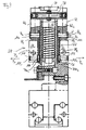
- Fig. 1 is a welding system generally designated 10.
- the welding system 10 comprises a contact belt feed unit 12, a contact part separation unit 14, a transport device 16 and a welding device 18.
- contact band 20 runs in the plane of the Fig. 1 Clocked driven by the contact belt feed unit 12 to the contact part separation unit 14.
- contact part separation unit 14 are separated by shearing the contact strip contact parts of defined length. These contact parts are received in the transport device 16 of an assembly 22 comprising a holding and a release device in a holding device receiving position and transported to a holding device dispensing position.
- the welding device 18 comprises a lower welding electrode 24 fixed relative to a device frame of the welding device and a movable welding electrode 26 rotatable about an electrode rotation axis E.
- the movable welding electrode 26 is connected via a welding electrode arm 28 to the pivot bearing about the electrode rotation axis E and in the direction of the Double arrow K on the electrode 24 to and from this movable.
- the welding electrode arm 28 is shown only in sections, partly by dashed lines.
- the cycle for the contact belt feed unit 12 and for the raising and lowering of the movable welding electrode 26 is transmitted via an indicated first eccentric cam 30 to a first plunger 32 which bears against the eccentric cam jacket surface 30a by spring force.
- a clock for moving the transport device 16 via a second eccentric cam 34 is transmitted to a voltage applied to the eccentric cam shell surface 34a second plunger 36 by spring force.
- the long leg 38b causes a displacement movement of the assembly 22 in up and down movement of the second plunger 36.
- the assembly 22 or a non-rotatably connected thereto component comprises a toothed pitch circle, which rolls on a rack during the sliding movement, so that the assembly 22 performs a combined sliding and rotating movement. This allows the overcoming of large distances between holding device receiving position and holding device delivery position.
- the kinematics of the assembly 22 at the transition from the holding device receiving position to the holding device discharge position and vice versa is in DE 197 55 166 A1 , the disclosure of which is to be part of the present application, described in detail.
- first plunger 32 40 movement is transmitted to a first link system 42 via a plate nut. From the first link system 42, the movement is transmitted to the welding electrode arm 28 via a second link system 44.
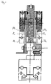
- Fig. 2 A more detailed description is the Fig. 2 refer to. First, however, the transport device 16 for feeding the welding device 18 to be joined with components (parts to be joined) will be described.
- a longitudinal end of the long leg 38b of the L-shaped lever 38 is rotatably received in a sliding member 46, which along a plane parallel to the plane of the Fig. 2 arranged guide rod 48 is slidably disposed.
- a connecting bolt 50 and a connecting rivet 52 which is non-rotatably connected to the rotatably mounted in the displacement element 46 connecting pin 50, the assembly 22 and a rolling part 54 are connected to the displacement element 46.
- the assembly 22, comprising the holding device 56 and the release device 58, and the rolling part 54 are connected to each other for common movement.
- Fig. 2 For example, the assembly 22, the rolling member 54 and the shifting member 46 are shown in solid lines at the left edge of the transport device 16 in the retainer delivery position.
- the holding device 56 'or the assembly 22' together with the rolling part 54 ' shown in dashed lines in the holding device receiving position, in which of the holding device 56, a joining part is received for transport in the holding device dispensing position.
- the toothing on the rolling part 54 disengages from the rack, whereupon the holding device 56 and with it the release device 58, the rolling part 54 and the displacement element 46 perform a linear movement into the holding device receiving position.
- the transport movement of the component ie the movement of the holding device 56 from the holding device receiving position into the holding device discharge position, follows the sequence in the reverse order.
- the assembly 22 further comprises a biasing compression spring 60, which biases the holding device 56 with respect to the release device 58 in a position in which the release device 58 is retracted with respect to the holding device 56.
- a lever mechanism 41 for raising and lowering the welding electrode arm 28 is shown.
- the welding electrode arm itself is in Fig. 2 Not shown.
- a closing force S acts on a roller 64, which is arranged rotatably on a first leg 42a of the first linkage system 42.
- the opening force O in the opposite direction acts on the first leg 42a.
- the opening force O is generated by compressing the welding gap opening pressure spring 66.
- the welding gap opening compression spring 66 is selected in spring rate such that it can lift the welding electrode arm 28 but is compressible by the first eccentric cam 30.
- the first linkage system is rotatably articulated about a stationary or transport frame-fixed frame pivot axis G at a fixed articulation point 68 on the device frame.
- the second link system 44 is pivoted at a first articulation location 70 about a first axis of rotation H.
- the second linkage system 44 is rotatable about the second pivot axis J at a second articulation point 72 Fig. 2 not shown movable electrode 62 connected.
- a slot 74 is formed in the second link system 44, which will be discussed below.
- the slot 74 may also be formed on the welding electrode arm 28 which the second link system 44 is articulated directly at the second pivot point 72.
- Fig. 3 is a section along the line VV in Fig. 2 shown.
- Fig. 5 Both the welding gap opening compression spring 66 and its spring abutment and the first and second linkage systems 42 and 44 are shown in section.
- the first link system 42 consists of two links 42 1 and 42 2 , which are connected to each other via a common cross member 98. On the Traverse 98, the roller 64 is rotatably supported.
- the links 42 1 and 42 2 of the first linkage system 42 are rotatably connected to the second linkage system 44 about the first axis of rotation H.
- the second link system 44 also includes a first link 44 1 and a second link 44 2 .
- the first link 44 1 of the second link system is articulated to the handlebar 42 1 of the first link system 42
- the second link 44 2 of the second link system is articulated to the handlebar 42 2 of the first link system 42.
- both first articulation points 70 1 and 70 2 have a common first axis of rotation H.
- the articulation of the second Lenkersystsems 44 on the first link system 42 is effected by bolts 100, which allow a relative rotation between the first and second link system.
- the Sch hasslektrodenarm 28 is formed in the example shown here by two substantially mutually parallel support 28 1 and 28 2 , which are connected to a common, not shown rotating shaft and rotate without the possibility of relative rotation to each other about the electrode axis of rotation E.
- the shafts of cone head rivets 104 are added.
- the conical head 106 of the conical head rivet 104 has a frustoconical head, which extends into the slot 74 of the second link system 44.
- the slots are also marked with subscript numbers to identify the assignment to the respective links of the second link system 44.
- the slots 74 1 and 74 2 of the second link system 44 have according to the cone opening angle of the conical head 106 inclined side surfaces 74 b 1 and 74 b 2 , against which the outer surface of the conical head 106 is applied.
- Fig. 4 is a section along the line VI-VI in Fig. 2 shown. Essentially only interested is the application of force to the carrier 28 1 and 28 2 by welding gap-closing compression springs 108 1 and 108 second Each of these welding gap-closing compression springs 108 1 and 108 2 exerts a force Z 1 or Z 2 on their respective assigned carrier 28 1 or 28 2 , which ensures a defined closing force in the welding ready position of the welding device.
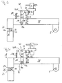
- FIGS. 5a to 5d is schematically simplified, the movement of the lever mechanism 41, the electrodes 24 and 26 and associated parts shown.
- the movement of the lever mechanism 41 and the pivot arm 28 is in the FIGS. 5a to 5d shown exaggerated for better perception.
- Fig. 5a the welding device 18 is opened, that is represented with a large welding gap width.
- a component 84 is arranged in the welding gap 25 in the welding gap 25 in the welding gap 25 in the welding gap 25 in the welding gap 25 in the welding gap 25 in the welding gap 25 in the welding gap 25 in the welding gap 25 in the welding gap 25 in the welding gap 25 in the welding gap 25 in the welding gap 25 in the welding gap 25 in the welding gap 25 in the welding gap 25, a component 84 is arranged.
- the first leg 42a of the first link system 42 is now pressed down against the biasing force of the welding gap opening compression spring 66 in Fig. 7b, resulting in a clockwise rotation of the first link system 42 about the frame pivot G.
- the first pivot point 70 also pivots clockwise about the frame rotation axis G, which under the action of the welding gap-closing compression spring 108 to an extension of the lever mechanism 41 leads (see Fig. 5b ).
- the compressive force of the welding gap closing compression spring 108 causes the Kegelkopfniet 104 abuts the slot bottom 74 a.
- Fig. 5c a position is reached in which the electrode active surface 26a rests on the component 84, so that a further closing of the welding gap 25 is mechanically inhibited by the component 84.
- the welding gap closing compression spring 108 still provides for abutment of the Kegelkopfniets 104 at the slot bottom 74 a.
- Fig. 5d the welding device 18 is shown in a fully ready for welding position.
- the lever mechanism 41 is in an extended state, which causes due to the movement inhibition in the closing direction of the Sch thoroughlyelektrodenarms 28 by the component 84 that the Kegelkopfniet 104 is no longer resting on the slot base 74 a and in the direction of movement of the electrode 26 from the lever mechanism 41 does not transmit force to the Sch hassleelektrodenarm 28 can be. Since the force of the welding gap opening compression spring 66 is overcome by the first eccentric cam 30 and the plate nut 40, only the welding gap closing compression spring 108 determines the force exerted on the component 84 by the movable electrode 26.
- This design of the completely ready for welding position has the further advantage that a low-friction setting of Welding electrode arm 28 is possible during welding. Namely, if the component 84 is provided with welding projections which are to be melted during a welding operation, it is possible to set the welding electrode arm 28 due to the play existing between the cone head rivet 104 and the slot base 74a, so that the contact between the welding electrode 26 and the component 84 will not interrupted. This allows a contact transition defined until the end of the welding process.
Landscapes
- Engineering & Computer Science (AREA)
- Robotics (AREA)
- Mechanical Engineering (AREA)
- Manufacturing & Machinery (AREA)
- Resistance Welding (AREA)
- Compression, Expansion, Code Conversion, And Decoders (AREA)
- Oscillators With Electromechanical Resonators (AREA)
- Medicines Containing Material From Animals Or Micro-Organisms (AREA)
- Discharge Heating (AREA)
- Superconductors And Manufacturing Methods Therefor (AREA)
Priority Applications (1)
| Application Number | Priority Date | Filing Date | Title |
|---|---|---|---|
| PL04021849T PL1522357T3 (pl) | 2003-10-10 | 2004-09-14 | Urządzenie do zamykania elektrody |
Applications Claiming Priority (2)
| Application Number | Priority Date | Filing Date | Title |
|---|---|---|---|
| DE10347074A DE10347074A1 (de) | 2003-10-10 | 2003-10-10 | Elektrodenschließmechanikvorrichtung |
| DE10347074 | 2003-10-10 |
Publications (3)
| Publication Number | Publication Date |
|---|---|
| EP1522357A2 EP1522357A2 (de) | 2005-04-13 |
| EP1522357A3 EP1522357A3 (de) | 2006-05-31 |
| EP1522357B1 true EP1522357B1 (de) | 2008-07-16 |
Family
ID=34306350
Family Applications (1)
| Application Number | Title | Priority Date | Filing Date |
|---|---|---|---|
| EP04021849A Expired - Lifetime EP1522357B1 (de) | 2003-10-10 | 2004-09-14 | Elektrodenschliessmechanikvorrichtung |
Country Status (5)
| Country | Link |
|---|---|
| EP (1) | EP1522357B1 (pl) |
| AT (1) | ATE401149T1 (pl) |
| DE (2) | DE10347074A1 (pl) |
| ES (1) | ES2309430T3 (pl) |
| PL (1) | PL1522357T3 (pl) |
Families Citing this family (2)
| Publication number | Priority date | Publication date | Assignee | Title |
|---|---|---|---|---|
| DE102011077754A1 (de) | 2011-06-17 | 2012-12-20 | Otto Bihler Handels-Beteiligungs-Gmbh | Schweißvorrichtung mit Wärmestrahlungsdetektion und Verfahren zur Überwachung des Schweißvorgangs |
| CN115213570A (zh) * | 2022-07-09 | 2022-10-21 | 广东国玉科技有限公司 | 用于电阻料带的光纤激光切割设备 |
Family Cites Families (6)
| Publication number | Priority date | Publication date | Assignee | Title |
|---|---|---|---|---|
| FR622674A (fr) * | 1926-02-06 | 1927-06-03 | Perfectionnements aux machines à souder électriques | |
| DE712053C (de) * | 1939-05-26 | 1941-10-10 | Aeg | Vorrichtung zum UEbertragen des Druckes vom Antrieb auf die bewegliche Elektrode beielektrischen Widerstandspunkt- oder Nahtschweissmaschinen |
| US3745842A (en) * | 1971-11-02 | 1973-07-17 | J Brems | Force transferring and multiplying system |
| US5046706A (en) * | 1988-05-10 | 1991-09-10 | Peninsular, Inc. | Power clamp |
| JPH0236083A (ja) * | 1988-07-22 | 1990-02-06 | Kiyouhou Seisakusho:Kk | パンタグラフ型ロボットアーム |
| DE19755166A1 (de) * | 1997-12-11 | 1999-06-17 | Bihler Otto Handels Beteiligungs Gmbh | Einrichtung und Verfahren zum Anbringen eines Kontaktmetallteils an einem Trägerteil durch Schweißen |
-
2003
- 2003-10-10 DE DE10347074A patent/DE10347074A1/de not_active Withdrawn
-
2004
- 2004-09-14 EP EP04021849A patent/EP1522357B1/de not_active Expired - Lifetime
- 2004-09-14 PL PL04021849T patent/PL1522357T3/pl unknown
- 2004-09-14 ES ES04021849T patent/ES2309430T3/es not_active Expired - Lifetime
- 2004-09-14 DE DE502004007596T patent/DE502004007596D1/de not_active Expired - Lifetime
- 2004-09-14 AT AT04021849T patent/ATE401149T1/de not_active IP Right Cessation
Also Published As
| Publication number | Publication date |
|---|---|
| EP1522357A2 (de) | 2005-04-13 |
| EP1522357A3 (de) | 2006-05-31 |
| DE502004007596D1 (de) | 2008-08-28 |
| ATE401149T1 (de) | 2008-08-15 |
| DE10347074A1 (de) | 2005-05-04 |
| ES2309430T3 (es) | 2008-12-16 |
| PL1522357T3 (pl) | 2008-11-28 |
Similar Documents
| Publication | Publication Date | Title |
|---|---|---|
| DE112010004255B4 (de) | Schalterbetätigungsmechanismus | |
| DE2820613A1 (de) | Reibungsschweissgeraet | |
| EP3110578B1 (de) | Werkzeug zum anbringen eines fuege- oder funktionselements an einem bauteilabschnitt | |
| EP2694231B1 (de) | TRANSFEREINRICHTUNG FÜR EINE PRESSE ODER PRESSENSTRAßE MIT ACHSANTRIEB UND AUSWECHSELBAREM GRUNDTRÄGER | |
| EP2684824B1 (de) | Separiervorrichtung | |
| EP3634834A1 (de) | Loslager, lenkgetriebe und lenksystem | |
| EP2236384B1 (de) | Verschlusskomponente für Stellzungen-Verschlussvorrichtung, Stellzungen-Verschlussvorrichtung und Weiche mit Stellzungen-Verschlussvorrichtung | |
| EP3752694B1 (de) | Autoparkvorrichtung | |
| EP3433193A1 (de) | Anschlagmodul zum positionsgenauen anhalten eines gegenstands | |
| DE102006036654B4 (de) | Keiltrieb mit Zwangsrückholeinrichtung | |
| CH653302A5 (de) | Transportkette. | |
| DE1503119A1 (de) | Bearbeitungsvorrichtung | |
| WO2007137629A1 (de) | Förderkette mit aufklappbarem greifköpf | |
| EP2835254B1 (de) | Presse zur Herstellung eines Presslings aus pulverförmigen Material | |
| EP4006275B1 (de) | Bewegungsanordnung für eine türgriffanordnung | |
| DE1477405C3 (de) | Einstellvorrichtung für Werkzeugträger, insbesondere für Bohrstangen von Feinbohrmaschinen mit einer drehbaren Bohrspindel | |
| DE2611285C2 (de) | Schrittschalteinrichtung für Drehelemente bei Werkzeugmaschinen | |
| EP1522357B1 (de) | Elektrodenschliessmechanikvorrichtung | |
| DE1123021B (de) | Schwenkeinrichtung zur Betaetigung eines elektrischen Endschalters | |
| DE102010007917B4 (de) | Handbetätigtes Werkzeug | |
| EP1522374B1 (de) | Bauteil-Transportvorrichtung | |
| DE20001092U1 (de) | Spannbackenvorrichtung | |
| WO2024231235A1 (de) | FORMSCHLIEßEINHEIT UND VERFAHREN ZUM BETREIBEN DERSELBEN | |
| DE2704267C2 (de) | Steuervorrichtung mit einem auf einer Schwenkachse schwenkbar gelagerten Haupthebel | |
| EP0672359B1 (de) | Vorrichtung für die Zuführung von Montageteilen |
Legal Events
| Date | Code | Title | Description |
|---|---|---|---|
| PUAI | Public reference made under article 153(3) epc to a published international application that has entered the european phase |
Free format text: ORIGINAL CODE: 0009012 |
|
| AK | Designated contracting states |
Kind code of ref document: A2 Designated state(s): AT BE BG CH CY CZ DE DK EE ES FI FR GB GR HU IE IT LI LU MC NL PL PT RO SE SI SK TR |
|
| AX | Request for extension of the european patent |
Extension state: AL HR LT LV MK |
|
| PUAL | Search report despatched |
Free format text: ORIGINAL CODE: 0009013 |
|
| AK | Designated contracting states |
Kind code of ref document: A3 Designated state(s): AT BE BG CH CY CZ DE DK EE ES FI FR GB GR HU IE IT LI LU MC NL PL PT RO SE SI SK TR |
|
| AX | Request for extension of the european patent |
Extension state: AL HR LT LV MK |
|
| 17P | Request for examination filed |
Effective date: 20061004 |
|
| 17Q | First examination report despatched |
Effective date: 20061115 |
|
| AKX | Designation fees paid |
Designated state(s): AT BE BG CH CY CZ DE DK EE ES FI FR GB GR HU IE IT LI LU MC NL PL PT RO SE SI SK TR |
|
| GRAP | Despatch of communication of intention to grant a patent |
Free format text: ORIGINAL CODE: EPIDOSNIGR1 |
|
| GRAS | Grant fee paid |
Free format text: ORIGINAL CODE: EPIDOSNIGR3 |
|
| GRAA | (expected) grant |
Free format text: ORIGINAL CODE: 0009210 |
|
| AK | Designated contracting states |
Kind code of ref document: B1 Designated state(s): AT BE BG CH CY CZ DE DK EE ES FI FR GB GR HU IE IT LI LU MC NL PL PT RO SE SI SK TR |
|
| REG | Reference to a national code |
Ref country code: GB Ref legal event code: FG4D Free format text: NOT ENGLISH |
|
| REG | Reference to a national code |
Ref country code: CH Ref legal event code: EP |
|
| REF | Corresponds to: |
Ref document number: 502004007596 Country of ref document: DE Date of ref document: 20080828 Kind code of ref document: P |
|
| REG | Reference to a national code |
Ref country code: IE Ref legal event code: FG4D Free format text: LANGUAGE OF EP DOCUMENT: GERMAN |
|
| REG | Reference to a national code |
Ref country code: PL Ref legal event code: T3 |
|
| REG | Reference to a national code |
Ref country code: ES Ref legal event code: FG2A Ref document number: 2309430 Country of ref document: ES Kind code of ref document: T3 |
|
| NLV1 | Nl: lapsed or annulled due to failure to fulfill the requirements of art. 29p and 29m of the patents act | ||
| PG25 | Lapsed in a contracting state [announced via postgrant information from national office to epo] |
Ref country code: NL Free format text: LAPSE BECAUSE OF FAILURE TO SUBMIT A TRANSLATION OF THE DESCRIPTION OR TO PAY THE FEE WITHIN THE PRESCRIBED TIME-LIMIT Effective date: 20080716 Ref country code: PT Free format text: LAPSE BECAUSE OF FAILURE TO SUBMIT A TRANSLATION OF THE DESCRIPTION OR TO PAY THE FEE WITHIN THE PRESCRIBED TIME-LIMIT Effective date: 20081216 |
|
| PG25 | Lapsed in a contracting state [announced via postgrant information from national office to epo] |
Ref country code: BG Free format text: LAPSE BECAUSE OF FAILURE TO SUBMIT A TRANSLATION OF THE DESCRIPTION OR TO PAY THE FEE WITHIN THE PRESCRIBED TIME-LIMIT Effective date: 20081016 Ref country code: SI Free format text: LAPSE BECAUSE OF FAILURE TO SUBMIT A TRANSLATION OF THE DESCRIPTION OR TO PAY THE FEE WITHIN THE PRESCRIBED TIME-LIMIT Effective date: 20080716 Ref country code: FI Free format text: LAPSE BECAUSE OF FAILURE TO SUBMIT A TRANSLATION OF THE DESCRIPTION OR TO PAY THE FEE WITHIN THE PRESCRIBED TIME-LIMIT Effective date: 20080716 |
|
| REG | Reference to a national code |
Ref country code: IE Ref legal event code: FD4D |
|
| BERE | Be: lapsed |
Owner name: OTTO BIHLER HANDELS-BETEILIGUNGS-GMBH Effective date: 20080930 |
|
| PG25 | Lapsed in a contracting state [announced via postgrant information from national office to epo] |
Ref country code: EE Free format text: LAPSE BECAUSE OF FAILURE TO SUBMIT A TRANSLATION OF THE DESCRIPTION OR TO PAY THE FEE WITHIN THE PRESCRIBED TIME-LIMIT Effective date: 20080716 Ref country code: DK Free format text: LAPSE BECAUSE OF FAILURE TO SUBMIT A TRANSLATION OF THE DESCRIPTION OR TO PAY THE FEE WITHIN THE PRESCRIBED TIME-LIMIT Effective date: 20080716 Ref country code: MC Free format text: LAPSE BECAUSE OF NON-PAYMENT OF DUE FEES Effective date: 20080930 Ref country code: IE Free format text: LAPSE BECAUSE OF FAILURE TO SUBMIT A TRANSLATION OF THE DESCRIPTION OR TO PAY THE FEE WITHIN THE PRESCRIBED TIME-LIMIT Effective date: 20080716 |
|
| REG | Reference to a national code |
Ref country code: CH Ref legal event code: PL |
|
| PLBE | No opposition filed within time limit |
Free format text: ORIGINAL CODE: 0009261 |
|
| STAA | Information on the status of an ep patent application or granted ep patent |
Free format text: STATUS: NO OPPOSITION FILED WITHIN TIME LIMIT |
|
| PG25 | Lapsed in a contracting state [announced via postgrant information from national office to epo] |
Ref country code: SK Free format text: LAPSE BECAUSE OF FAILURE TO SUBMIT A TRANSLATION OF THE DESCRIPTION OR TO PAY THE FEE WITHIN THE PRESCRIBED TIME-LIMIT Effective date: 20080716 Ref country code: RO Free format text: LAPSE BECAUSE OF FAILURE TO SUBMIT A TRANSLATION OF THE DESCRIPTION OR TO PAY THE FEE WITHIN THE PRESCRIBED TIME-LIMIT Effective date: 20080716 |
|
| 26N | No opposition filed |
Effective date: 20090417 |
|
| PG25 | Lapsed in a contracting state [announced via postgrant information from national office to epo] |
Ref country code: BE Free format text: LAPSE BECAUSE OF NON-PAYMENT OF DUE FEES Effective date: 20080930 |
|
| PG25 | Lapsed in a contracting state [announced via postgrant information from national office to epo] |
Ref country code: LI Free format text: LAPSE BECAUSE OF NON-PAYMENT OF DUE FEES Effective date: 20080930 Ref country code: CH Free format text: LAPSE BECAUSE OF NON-PAYMENT OF DUE FEES Effective date: 20080930 Ref country code: AT Free format text: LAPSE BECAUSE OF NON-PAYMENT OF DUE FEES Effective date: 20080914 |
|
| PG25 | Lapsed in a contracting state [announced via postgrant information from national office to epo] |
Ref country code: SE Free format text: LAPSE BECAUSE OF FAILURE TO SUBMIT A TRANSLATION OF THE DESCRIPTION OR TO PAY THE FEE WITHIN THE PRESCRIBED TIME-LIMIT Effective date: 20081016 |
|
| PG25 | Lapsed in a contracting state [announced via postgrant information from national office to epo] |
Ref country code: LU Free format text: LAPSE BECAUSE OF NON-PAYMENT OF DUE FEES Effective date: 20080914 Ref country code: CY Free format text: LAPSE BECAUSE OF FAILURE TO SUBMIT A TRANSLATION OF THE DESCRIPTION OR TO PAY THE FEE WITHIN THE PRESCRIBED TIME-LIMIT Effective date: 20080716 Ref country code: HU Free format text: LAPSE BECAUSE OF FAILURE TO SUBMIT A TRANSLATION OF THE DESCRIPTION OR TO PAY THE FEE WITHIN THE PRESCRIBED TIME-LIMIT Effective date: 20090117 |
|
| PG25 | Lapsed in a contracting state [announced via postgrant information from national office to epo] |
Ref country code: TR Free format text: LAPSE BECAUSE OF FAILURE TO SUBMIT A TRANSLATION OF THE DESCRIPTION OR TO PAY THE FEE WITHIN THE PRESCRIBED TIME-LIMIT Effective date: 20080716 |
|
| PG25 | Lapsed in a contracting state [announced via postgrant information from national office to epo] |
Ref country code: GR Free format text: LAPSE BECAUSE OF FAILURE TO SUBMIT A TRANSLATION OF THE DESCRIPTION OR TO PAY THE FEE WITHIN THE PRESCRIBED TIME-LIMIT Effective date: 20081017 |
|
| REG | Reference to a national code |
Ref country code: FR Ref legal event code: PLFP Year of fee payment: 13 |
|
| REG | Reference to a national code |
Ref country code: FR Ref legal event code: PLFP Year of fee payment: 14 |
|
| REG | Reference to a national code |
Ref country code: FR Ref legal event code: PLFP Year of fee payment: 15 |
|
| PGFP | Annual fee paid to national office [announced via postgrant information from national office to epo] |
Ref country code: GB Payment date: 20220920 Year of fee payment: 19 Ref country code: DE Payment date: 20220630 Year of fee payment: 19 Ref country code: CZ Payment date: 20220912 Year of fee payment: 19 |
|
| PGFP | Annual fee paid to national office [announced via postgrant information from national office to epo] |
Ref country code: PL Payment date: 20220902 Year of fee payment: 19 Ref country code: FR Payment date: 20220922 Year of fee payment: 19 |
|
| PGFP | Annual fee paid to national office [announced via postgrant information from national office to epo] |
Ref country code: IT Payment date: 20220926 Year of fee payment: 19 Ref country code: ES Payment date: 20221121 Year of fee payment: 19 |
|
| P01 | Opt-out of the competence of the unified patent court (upc) registered |
Effective date: 20230512 |
|
| REG | Reference to a national code |
Ref country code: DE Ref legal event code: R119 Ref document number: 502004007596 Country of ref document: DE |
|
| PG25 | Lapsed in a contracting state [announced via postgrant information from national office to epo] |
Ref country code: CZ Free format text: LAPSE BECAUSE OF NON-PAYMENT OF DUE FEES Effective date: 20230914 |
|
| GBPC | Gb: european patent ceased through non-payment of renewal fee |
Effective date: 20230914 |
|
| PG25 | Lapsed in a contracting state [announced via postgrant information from national office to epo] |
Ref country code: GB Free format text: LAPSE BECAUSE OF NON-PAYMENT OF DUE FEES Effective date: 20230914 |
|
| PG25 | Lapsed in a contracting state [announced via postgrant information from national office to epo] |
Ref country code: GB Free format text: LAPSE BECAUSE OF NON-PAYMENT OF DUE FEES Effective date: 20230914 Ref country code: FR Free format text: LAPSE BECAUSE OF NON-PAYMENT OF DUE FEES Effective date: 20230930 Ref country code: DE Free format text: LAPSE BECAUSE OF NON-PAYMENT OF DUE FEES Effective date: 20240403 |
|
| PG25 | Lapsed in a contracting state [announced via postgrant information from national office to epo] |
Ref country code: PL Free format text: LAPSE BECAUSE OF NON-PAYMENT OF DUE FEES Effective date: 20230914 |
|
| PG25 | Lapsed in a contracting state [announced via postgrant information from national office to epo] |
Ref country code: PL Free format text: LAPSE BECAUSE OF NON-PAYMENT OF DUE FEES Effective date: 20230914 |
|
| REG | Reference to a national code |
Ref country code: ES Ref legal event code: FD2A Effective date: 20241031 |
|
| PG25 | Lapsed in a contracting state [announced via postgrant information from national office to epo] |
Ref country code: IT Free format text: LAPSE BECAUSE OF NON-PAYMENT OF DUE FEES Effective date: 20230914 |
|
| PG25 | Lapsed in a contracting state [announced via postgrant information from national office to epo] |
Ref country code: IT Free format text: LAPSE BECAUSE OF NON-PAYMENT OF DUE FEES Effective date: 20230914 |
|
| PG25 | Lapsed in a contracting state [announced via postgrant information from national office to epo] |
Ref country code: ES Free format text: LAPSE BECAUSE OF NON-PAYMENT OF DUE FEES Effective date: 20230915 |
|
| PG25 | Lapsed in a contracting state [announced via postgrant information from national office to epo] |
Ref country code: ES Free format text: LAPSE BECAUSE OF NON-PAYMENT OF DUE FEES Effective date: 20230915 |