EP1522234B1 - Method for producing brushes, particularly toothbrushes - Google Patents
Method for producing brushes, particularly toothbrushes Download PDFInfo
- Publication number
- EP1522234B1 EP1522234B1 EP04024201.8A EP04024201A EP1522234B1 EP 1522234 B1 EP1522234 B1 EP 1522234B1 EP 04024201 A EP04024201 A EP 04024201A EP 1522234 B1 EP1522234 B1 EP 1522234B1
- Authority
- EP
- European Patent Office
- Prior art keywords
- bristle
- bristle bundles
- motion
- hole
- bundles
- Prior art date
- Legal status (The legal status is an assumption and is not a legal conclusion. Google has not performed a legal analysis and makes no representation as to the accuracy of the status listed.)
- Active
Links
- 238000004519 manufacturing process Methods 0.000 title description 6
- 238000000034 method Methods 0.000 claims description 33
- 238000003780 insertion Methods 0.000 claims description 3
- 230000037431 insertion Effects 0.000 claims description 3
- 230000014759 maintenance of location Effects 0.000 claims 2
- 238000000926 separation method Methods 0.000 claims 2
- 238000003860 storage Methods 0.000 description 5
- 239000000969 carrier Substances 0.000 description 2
- 230000002093 peripheral effect Effects 0.000 description 2
- 238000002360 preparation method Methods 0.000 description 2
- 239000000463 material Substances 0.000 description 1
- 238000000465 moulding Methods 0.000 description 1
- 238000007789 sealing Methods 0.000 description 1
Images

Classifications
-
- A—HUMAN NECESSITIES
- A46—BRUSHWARE
- A46D—MANUFACTURE OF BRUSHES
- A46D3/00—Preparing, i.e. Manufacturing brush bodies
- A46D3/08—Parts of brush-making machines
- A46D3/082—Magazines for bristles; Feeding bristles to magazines; Knot picking
-
- A—HUMAN NECESSITIES
- A46—BRUSHWARE
- A46B—BRUSHES
- A46B2200/00—Brushes characterized by their functions, uses or applications
- A46B2200/10—For human or animal care
- A46B2200/1066—Toothbrush for cleaning the teeth or dentures
Definitions
- the present invention relates to a method for producing brushes, in particular toothbrushes, in which the bristle bundles are divided from at least one bristle supply in a first direction of movement by a single compartment element which bears sealingly against an opening of the bristle supply and is fastened to at least one bristle carrier by the latter Abforcelement be removed in a second direction of movement, wherein, after in the first direction of movement a plurality of bristle bundles have been divided with the one Abwellement, the Abforcelement is stopped and these bristle bundles are removed simultaneously in the second direction of movement from the Abforcelement.
- the present invention is based on the problem to improve the generic method in terms of its speed and performance.
- a plurality of bristle bundles with a first circular segment-shaped movement can be divided off from a bristle supply and provided at the same time for attachment to at least one bristle carrier.
- the performance of the method can be improved.
- inventive Methods for providing bundles of bristles for attachment to the bristle carrier are initially separated from a bristle supply by a compartment element in a first circular segment-shaped movement direction. After the bundles of bristles have been divided by means of the dividing element, the dividing element is stopped and the bundles of bristles held on the dividing element are grasped in a second direction of movement, preferably orthogonal to the first direction of movement, and removed at the same time.
- the bristle bundles are removed substantially simultaneously, namely that the bundles of bristles initially provided in a first direction of movement are removed from the dividing element before it is set in motion again for dividing further bristle bundles.
- the bundles of bristles removed in the second direction of movement are finished bundles of bristles, which can be seen as individual bundles on the finished brush or form the subset of an enlarged bundle of bristles in which a plurality of bristle bundles are combined with identical or substantially identical number of bristle filaments.
- the bristle bundles thus produced are removed from the compartment element for attachment to the bristle carrier. This means that the bristle bundles are removed from the compartment element.
- the bristle bundles can either be gripped with a stuffing tool in a manner known per se and fastened directly to the bristle carrier.
- the bristle bundles can also be transferred to a holder for further preparation of the bristle bundles for later attachment to a bristle carrier.
- the bristle bundles are simultaneously introduced into at least one perforated field pattern in the second direction of movement, which corresponds to a bristle arrangement of a single bristle carrier.
- the perforated field pattern according to the invention is a pattern of holes which are provided in an arrangement corresponding to the size, number and relative orientation of the bristles of the finished brush. Since the bundles of bristles are introduced at the same time in the or the hole field pattern in the second movement, such a perforated field pattern can be stuffed faster with bristle bundles.
- the bristle bundles are held in the second direction of movement via a common stuffing tool and at the same time introduced into different holes of the at least one hole field pattern.
- the stuffing tool required to carry out this preferred method of operation can be designed, despite increased output, with only slightly higher mass than a stuffing tool for stuffing only one bristle bundle.
- the bristle bundles are held in the second direction of movement over a plurality of stuffing tools and at the same time introduced into different holes of the at least one hole field pattern.
- the different stuffing tools are preferably coordinated so that even in the event of failure of one or more Stopftechnikmaschineen the still working stuffing tools can ensure production.
- the bristle bundles are simultaneously introduced into corresponding holes of different perforated field patterns in the second direction of movement.
- This preferred process facilitates mass production of a plurality of identical hole pattern brushes.
- the relative movement between the hole field pattern and the stuffing tool in a direction substantially transverse to the extension of the holes required to stuff a hole field pattern to provide empty holes for the stuffing device in this embodiment detects a plurality of hole field patterns whose corresponding holes are stuffed with bristle bundles at the same time ,
- This preferred development of the method according to the invention initially simplifies the structural design of the device required for carrying out the method.
- the preferred method is particularly suitable for the preparation of bundles of bristles which are stuffed into a perforated field pattern whose holes have identical lateral spacing from each other. The lateral spacing of the recesses provided on the dividing element and accommodating the bristle bundles corresponds exactly to this lateral spacing of individual holes of the perforated field pattern.
- the prepared bundles of bristles taken from the dividing element at the removal position are directly introduced into adjacent holes of the perforated field pattern in this preferred embodiment without changing their lateral spacing.
- the movement in the second direction of movement may be an exclusively linear movement, resulting in a fast and simple procedure.
- the bristle bundles are held in the second direction of movement via a common stuffing tool and at the same time introduced into a single hole of the perforated field pattern.
- the bundles of bristles are thereby conveyed while maintaining their lateral distance to an opening of a hole and moved toward each other when introduced into the hole.
- the bristle bundles slide on insertion into the hole on the surface of a funnel-shaped opening of the hole. This ensures a safe introduction of the bristle bundles into the hole with a simple configuration of the device for carrying out the method.
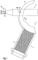
- FIG. 1 and 2 each schematically show essential parts of a device for carrying out the method, which has a bristle storage container 2, a circular-arc-shaped dividing element 4 and a stuffing tool 6.
- the compartment element 4 lies with its outer peripheral surface 8 sealingly against an opening of the bristle reservoir 2. Furthermore, the compartment element 4 has two recesses 10a, 10b positioned next to one another.
- bristle filaments 12 are removed from the storage container 2 by means of the compartment element 4.
- a certain number of bristle filaments 12 are removed from the bristle storage container 2 only when the recesses 10a, 10b of the compartment element 4 at the opening the bristle reservoir 2 are passed.
- the bristle filaments 12 are thereby divided into two different bristle bundles 14 in a controlled manner.
- the bristle bundles 14 are guided in a continuous movement in the direction of the arrow P to a stuffing tool 6.
- the circular compartment element 4 terminates the first direction of movement only when the bristle bundles 14 have reached a position in which the bristle bundles 14 can be introduced in a linear movement in holes 16 provided for them of a bristle carrier 18 at the same time.
- this second movement which is substantially orthogonal to the first movement, ie substantially perpendicular to the instantaneous movement of the bristle bundles 14 immediately prior to stopping of the dividing element 4 for removal of the bristle bundles 14, the bristle bundles 14a, 14b are spaced apart so that the distance between the bristle bundles 14a, 14b, the distance between the holes 16a, 16b and the distance between the recesses 10a, 10b (at right angles to the direction of movement of the stuffing tool 6) corresponds.
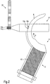
- FIG. 2 is different from the one in FIG. 1 shown embodiment in that the bristle bundles are introduced into a single hole field plate 20. Thereafter, the perforated field plate 20 can either be attached directly to a bristle carrier or serves as a support while the bundles of bristles are attached to a bristle carrier.
- FIG. 2 - as well as in the FIGS. 4 . 5 -
- the introduction of the bristle bundles in the hole field plate 20 is shown schematically simplified. In fact, the bundles 14a, 14b are removed from the tamping tool and introduced into the perforated field plate 20 in the axial direction, ie perpendicular to the plane of the drawing.
- the dividing element 4 abuts on its outer circumferential surface 8 on a counter surface, are closed by the recesses 10a, 10b.
- the bristle bundles 14a, 14b can be removed from the compartment element 4, for example, by a punch engaging in the recesses 10a, 10b.
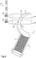
- FIGS. 3 to 5 show further embodiments of the method according to the invention.
- FIGS. 1 and 2 like parts, marked with the same reference numerals.
- the in the FIG. 3 shown bristle arrangement has two stuffing tools 22a, 22b.
- the sealing element abutting against the bristle storage container 2 is moved in a first circular arc-shaped movement in the direction of the arrow P.
- bristle filaments are removed from the first recess 24b from the bristle storage container 2 and divided into a bristle bundle 26b.
- further bristle filaments 12 are divided into a bristle bundle 26a by means of the second recess 24a.
- the bristle bundles 26 are guided in the direction of the arrow P until they are in a position in which the bundles of bristles 26a, 26b are each moved simultaneously by a tamping tool 24a, 24b into a respective hole 28a, 28b of one of the bristle carriers 30a, 30b can be introduced.
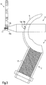
- FIG. 4 is different from the one in FIG. 3 shown embodiment in that the bristle bundles are simultaneously introduced into corresponding holes of a plurality of hole field pattern formed in a perforated field plate.
- FIG. 5 shows a further embodiment in which the bristle bundles 16a, 16b are introduced into a single hole of a perforated field pattern.
- FIG. 5 shows a perforated field plate 19 having a hole 17 with a funnel-shaped opening.
- the bristle bundles 16a, 16b become, as in the in FIG. 1 shown embodiment, separated from the bristle supply 2 and conveyed by the Abteielement 4 to the stuffing tool 6.
- the bristle bundles are then removed at the same time by means of the stuffing tool 6 of the compartment element 4 and are conveyed in a linear movement to the mouth of the hole 17.
- the bristle bundles 16a, 16b are then introduced into the hole 17 at the same time, with the bristle bundles 16a, 16b sliding off the funnel-shaped surface of the opening.
- the distance between the recesses of the compartment element and the distance between the holes to be stuffed is preferably matched to one another such that the divided bristle bundles can be introduced into the holes while maintaining their lateral spacing.
- the divided bristle bundles the bundles of bristles which can be seen as individual bristle bundles on the finished brush, can be, on the other hand, the divided bristle bundles can form the subset of an enlarged bristle bundle.
Description
Die vorliegende Erfindung betrifft ein Verfahren zur Herstellung von Bürsten, insbesondere Zahnbürsten, bei dem Borstenbündel in einer ersten Bewegungsrichtung aus mindestens einem Borstenvorrat von einem mit seiner äußeren Umfangsfläche dichtend an einer Öffnung des Borstenvorrats anliegenden einzigen Abteilelement abgeteilt und zur Befestigung an mindestens einem Borstenträger von dem Abteilelement in einer zweiten Bewegungsrichtung entnommen werden, wobei, nachdem in der ersten Bewegungsrichtung mehrere Borstenbündel mit dem einen Abteilelement abgeteilt worden sind, das Abteilelement angehalten wird und diese Borstenbündel in der zweiten Bewegungsrichtung zeitgleich aus dem Abteilelement entnommen werden.The present invention relates to a method for producing brushes, in particular toothbrushes, in which the bristle bundles are divided from at least one bristle supply in a first direction of movement by a single compartment element which bears sealingly against an opening of the bristle supply and is fastened to at least one bristle carrier by the latter Abteilelement be removed in a second direction of movement, wherein, after in the first direction of movement a plurality of bristle bundles have been divided with the one Abteilelement, the Abteilelement is stopped and these bristle bundles are removed simultaneously in the second direction of movement from the Abteilelement.
Ein derartiges Verfahren ist aus der
Ähnliche Verfahren zur Herstellung von Bürsten sind dem Fachmann aus der
Die vorbekannten Verfahren bedürfen der Verbesserung hinsichtlich Geschwindigkeit und Leistungsfähigkeit.The prior art methods require improvement in speed and performance.
Der vorliegenden Erfindung liegt das Problem zugrunde, das gattungsbildende Verfahren hinsichtlich seiner Geschwindigkeit und Leistungsfähigkeit zu verbessern.The present invention is based on the problem to improve the generic method in terms of its speed and performance.
Das der Erfindung zugrundeliegende technische Problem wird erfindungsgemäß durch ein Verfahren mit den Merkmalen von Anspruch 1 gelöst.The technical problem underlying the invention is achieved by a method having the features of claim 1.
Bei dem erfindungsgemäßen Verfahren können mehrere Borstenbündel mit einer ersten kreissegmentförmigen Bewegung aus einem Borstenvorrat abgeteilt und zur Befestigung an mindestens einem Borstenträger zeitgleich bereitgestellt werden. Dies führt dazu, dass die Leistungsfähigkeit des Verfahrens verbessert werden kann. Bei dem erfindungsgemäßen Verfahren werden zur Bereitstellung von Borstenbündeln zur Befestigung am Borstenträger diese zunächst von einem Abteilelement in einer ersten kreissegmentförmigen Bewegungsrichtung aus einem Borstenvorrat abgeteilt. Nachdem die Borstenbündel mittels des Abteilelementes abgeteilt worden sind, wird das Abteilelement angehalten und die an dem Abteilelement gehaltenen Borstenbündel werden in einer zweiten, vorzugsweise zur ersten Bewegungsrichtung orthogonalen Bewegungsrichtung erfasst und zeitgleich entnommen. Zeitgleich im Sinne der vorliegenden Erfindung bedeutet, dass die Borstenbündel im Wesentlichen zeitgleich entnommen werden, nämlich dass die über das Abteielement zunächst in einer ersten Bewegungsrichtung bereitgestellten Borstenbündel von dem Abteilelement entnommen werden, bevor dieses zum Abteilen weiterer Borstenbündel erneut in Bewegung gesetzt wird. Die bei der zweiten Bewegungsrichtung entnommenen Borstenbündel sind fertige Borstenbündel, die als einzelne Bündel an der fertigen Bürste zu sehen sind oder aber die Teilmenge eines vergrößerten Borstenbündels bilden, in dem mehrere Borstenbündel mit identischer oder im Wesentlichen identischer Anzahl von Borstenfilamenten vereinigt sind. Bei dem erfindungsgemäßen Verfahren werden die so hergestellten Borstenbündel zur Befestigung an dem Borstenträger von dem Abteilelement entnommen. Dies bedeutet, dass die Borstenbündel von dem Abteilelement entfernt werden. Die Borstenbündel können hierzu entweder in an sich bekannter Weise mit einem Stopfwerkzeug gegriffen und unmittelbar an dem Borstenträger befestigt werden. Alternativ können die Borstenbündel auch an eine Halterung zur weiteren Vorbereitung der Borstenbündel zur späteren Befestigung an einem Borstenträger überführt werden.In the method according to the invention, a plurality of bristle bundles with a first circular segment-shaped movement can be divided off from a bristle supply and provided at the same time for attachment to at least one bristle carrier. As a result, the performance of the method can be improved. In the inventive Methods for providing bundles of bristles for attachment to the bristle carrier are initially separated from a bristle supply by a compartment element in a first circular segment-shaped movement direction. After the bundles of bristles have been divided by means of the dividing element, the dividing element is stopped and the bundles of bristles held on the dividing element are grasped in a second direction of movement, preferably orthogonal to the first direction of movement, and removed at the same time. At the same time in the sense of the present invention means that the bristle bundles are removed substantially simultaneously, namely that the bundles of bristles initially provided in a first direction of movement are removed from the dividing element before it is set in motion again for dividing further bristle bundles. The bundles of bristles removed in the second direction of movement are finished bundles of bristles, which can be seen as individual bundles on the finished brush or form the subset of an enlarged bundle of bristles in which a plurality of bristle bundles are combined with identical or substantially identical number of bristle filaments. In the method according to the invention, the bristle bundles thus produced are removed from the compartment element for attachment to the bristle carrier. This means that the bristle bundles are removed from the compartment element. For this purpose, the bristle bundles can either be gripped with a stuffing tool in a manner known per se and fastened directly to the bristle carrier. Alternatively, the bristle bundles can also be transferred to a holder for further preparation of the bristle bundles for later attachment to a bristle carrier.
Erfindungsgemäß werden die Borstenbündel in der zweiten Bewegungsrichtung zeitgleich in zumindest ein Lochfeldmuster eingebracht, welches einer Borstenanordnung eines einzigen Borstenträgers entspricht. Das Lochfeldmuster im Sinne der Erfindung ist ein Muster von Löchern, die in einer der Größe, Anzahl und relativen Ausrichtung der Borsten der fertigen Bürste entsprechenden Anordnung vorgesehen sind. Da die Borstenbündel in der zweiten Bewegung zeitgleich in das bzw. die Lochfeldmuster eingebracht werden, kann ein derartiges Lochfeldmuster schneller mit Borstenbündeln gestopft werden.According to the invention, the bristle bundles are simultaneously introduced into at least one perforated field pattern in the second direction of movement, which corresponds to a bristle arrangement of a single bristle carrier. The perforated field pattern according to the invention is a pattern of holes which are provided in an arrangement corresponding to the size, number and relative orientation of the bristles of the finished brush. Since the bundles of bristles are introduced at the same time in the or the hole field pattern in the second movement, such a perforated field pattern can be stuffed faster with bristle bundles.
Das zeitgleiche Bestopfen von mehreren Lochfeldmustern, die in einer gemeinsamen Lochfeldplatte ausgebildet sind, kann vereinfacht durchgeführt werden und im Übrigen kann auch der zeitaufwendigste Schritt zur Vorbereitung der Borstenbündel zur nachfolgenden Befestigung durch Umspritzen mit Kunststoffmasse beschleunigt werden.The simultaneous filling of several hole field patterns, which in a common Perforated field plate are formed, can be performed in a simplified and incidentally, the most time-consuming step for preparing the bristle bundles for subsequent attachment by molding with plastic material can be accelerated.
Vorzugsweise werden bei dem erfindungsgemäßen Verfahren die Borstenbündel in der zweiten Bewegungsrichtung über ein gemeinsames Stopfwerkzeug gehalten und zeitgleich in unterschiedliche Löcher des wenigstens einen Lochfeldmusters eingebracht. Das zur Durchführung dieser bevorzugten Verfahrensführung erforderliche Stopfwerkzeug kann trotz erhöhten Ausstoßes mit nur unwesentlich höherer Masse als ein Stopfwerkzeug zum Stopfen lediglich eines Borstenbündels ausgebildet sein.Preferably, in the method according to the invention, the bristle bundles are held in the second direction of movement via a common stuffing tool and at the same time introduced into different holes of the at least one hole field pattern. The stuffing tool required to carry out this preferred method of operation can be designed, despite increased output, with only slightly higher mass than a stuffing tool for stuffing only one bristle bundle.
Bei einer weiteren bevorzugten Ausgestaltung des erfindungsgemäßen Verfahrens werden die Borstenbündel in der zweiten Bewegungsrichtung über mehrere Stopfwerkzeuge gehalten und zeitgleich in unterschiedliche Löcher des wenigstens einen Lochfeldmusters eingebracht. Die unterschiedlichen Stopfwerkzeuge werden vorzugsweise so aufeinander abgestimmt, dass auch im Falle eines Ausfalles von einem oder mehreren Stopfwerkzeugen die noch funktionsfähigen Stopfwerkzeuge die Produktion gewährleisten können.In a further preferred embodiment of the method according to the invention, the bristle bundles are held in the second direction of movement over a plurality of stuffing tools and at the same time introduced into different holes of the at least one hole field pattern. The different stuffing tools are preferably coordinated so that even in the event of failure of one or more Stopfwerkzeugen the still working stuffing tools can ensure production.
Gemäß einer vorteilhaften Weiterbildung werden die Borstenbündel in der zweiten Bewegungsrichtung zeitgleich in korrespondierende Löcher unterschiedlicher Lochfeldmuster eingebracht. Diese bevorzugte Verfahrensführung erleichtert die Massenherstellung von einer Vielzahl von Bürsten mit identischem Lochfeldmuster. Die zum Bestopfen eines Lochfeldmusters erforderliche Relativbewegung zwischen dem Lochfeldmuster und dem Stopfwerkzeug in einer Richtung im Wesentlichen quer zur Erstreckung der Löcher zum Bereitstellen jeweils leerer Löcher für die Stopfeinrichtung, erfasst bei dieser Ausführungsform eine Vielzahl von Lochfeldmustern, deren korrespondierende Löcher jeweils zeitgleich mit Borstenbündeln gestopft werden.According to an advantageous development, the bristle bundles are simultaneously introduced into corresponding holes of different perforated field patterns in the second direction of movement. This preferred process facilitates mass production of a plurality of identical hole pattern brushes. The relative movement between the hole field pattern and the stuffing tool in a direction substantially transverse to the extension of the holes required to stuff a hole field pattern to provide empty holes for the stuffing device in this embodiment detects a plurality of hole field patterns whose corresponding holes are stuffed with bristle bundles at the same time ,
Gemäß einer bevorzugten Weiterbildung der vorliegenden Erfindung werden die Borstenbündel in der zweiten Bewegungsrichtung unter Beibehalt ihres seitlichen Abstandes zeitgleich in die Löcher des wenigstens einen Lochfeldmusters eingebracht. Diese bevorzugte Weiterbildung des erfindungsgemäßen Verfahrens vereinfacht zunächst den konstruktiven Aufbau der zur Durchführung des Verfahrens erforderlichen Vorrichtung. Ferner eignet sich das bevorzugte Verfahren insbesondere zur Vorbereitung von Borstenbündeln, die in ein Lochfeldmuster gestopft werden, deren Löcher identischen seitlichen Abstand zueinander haben. Der seitliche Abstand der an dem Abteilelement vorgesehenen und die Borstenbündel aufnehmenden Ausnehmungen entspricht genau diesem seitlichen Abstand einzelner Löcher des Lochfeldmusters. Die an der Entnahmeposition von dem Abteilelement entnommenen, vorbereiteten Borstenbündel werden bei dieser bevorzugten Ausgestaltung ohne Veränderung ihres seitlichen Abstandes unmittelbar in benachbarte Löcher des Lochfeldmusters eingebracht. Hierbei kann die Bewegung in der zweiten Bewegungsrichtung eine ausschließlich lineare Bewegung sein, wodurch sich eine schnelle und einfache Verfahrensführung ergibt.According to a preferred embodiment of the present invention, the bristle bundles in the second direction of movement while maintaining its lateral distance at the same time introduced into the holes of the at least one hole field pattern. This preferred development of the method according to the invention initially simplifies the structural design of the device required for carrying out the method. Furthermore, the preferred method is particularly suitable for the preparation of bundles of bristles which are stuffed into a perforated field pattern whose holes have identical lateral spacing from each other. The lateral spacing of the recesses provided on the dividing element and accommodating the bristle bundles corresponds exactly to this lateral spacing of individual holes of the perforated field pattern. The prepared bundles of bristles taken from the dividing element at the removal position are directly introduced into adjacent holes of the perforated field pattern in this preferred embodiment without changing their lateral spacing. In this case, the movement in the second direction of movement may be an exclusively linear movement, resulting in a fast and simple procedure.
Bei einer weiteren bevorzugten Ausgestaltung des erfindungsgemäßen Verfahrens werden die Borstenbündel in der zweiten Bewegungsrichtung über ein gemeinsames Stopfwerkzeug gehalten und zeitgleich in ein einziges Loch des Lochfeldmusters eingebracht. Diese vorteilhafte Verfahrensführung bringt den Vorteil mit sich, dass unterschiedliche Bündelgrößen hergestellt werden können. Der vorstehend beschriebene Zusammenhang zwischen der Borstenfilamente aufnehmenden Ausnehmung des Abteilelementes und der Größe des Loches wird damit aufgelöst.In a further preferred embodiment of the method according to the invention, the bristle bundles are held in the second direction of movement via a common stuffing tool and at the same time introduced into a single hole of the perforated field pattern. This advantageous process procedure has the advantage that different bundle sizes can be produced. The above-described relationship between the bristle filament receiving recess of the compartment element and the size of the hole is thus resolved.
Vorzugsweise werden hierbei die Borstenbündel unter Beibehalt ihres seitlichen Abstandes bis an eine Mündung eines Loches gefördert und beim Einbringen in das Loch aufeinander zu bewegt.Preferably, the bundles of bristles are thereby conveyed while maintaining their lateral distance to an opening of a hole and moved toward each other when introduced into the hole.
Gemäß einer bevorzugten Weiterbildung der vorliegenden Erfindung gleiten die Borstenbündel beim Einbringen in das Loch auf der Oberfläche einer trichterförmigen Öffnung des Loches ab. Dies gewährleistet ein sicheres Einbringen der Borstenbündel in das Loch bei einfacher Ausgestaltung der Vorrichtung zur Durchführung des Verfahrens.According to a preferred embodiment of the present invention, the bristle bundles slide on insertion into the hole on the surface of a funnel-shaped opening of the hole. This ensures a safe introduction of the bristle bundles into the hole with a simple configuration of the device for carrying out the method.
Weitere Einzelheiten, Vorteile und Merkmale der vorliegenden Erfindung ergeben sich aus der nachfolgenden Beschreibung einiger Ausführungsbeispiele in Verbindung mit der Zeichnung. In dieser zeigen:
- Figur 1
- eine schematische Ansicht eines ersten Ausführungsbeispiels, in dem mehrere Borstenbündel an einem Borstenträger befestigt werden;
Figur 2- eine schematische Ansicht eines zweiten Ausführungsbeispiels, in dem mehrere Borstenbündel in eine Lochfeldplatte eingebracht werden;
- Figur 3
- eine schematische Ansicht eines dritten Ausführungsbeispiels, in dem Borstenbündel in korrespondierende Löcher von unterschiedlichen Borstenträgern eingebracht werden;
Figur 4- eine schematische Ansicht eines vierten Ausführungsbeispiels, in dem mehrere Borstenbündel mittels zwei Stopfwerkzeugen in korrespondierende Löcher einer Lochfeldplatte eingebracht werden; und
- Figur 5
- eine schematische Ansicht eines fünften Ausführungsbeispiels, in dem mehrere Borstenbündel in ein Loch eines Borstenträgers eingebracht werden.
- FIG. 1
- a schematic view of a first embodiment in which a plurality of bristle bundles are attached to a bristle carrier;
- FIG. 2
- a schematic view of a second embodiment in which a plurality of bristle bundles are introduced into a perforated field plate;
- FIG. 3
- a schematic view of a third embodiment in which bristle bundles are introduced into corresponding holes of different bristle carriers;
- FIG. 4
- a schematic view of a fourth embodiment, in which a plurality of bristle bundles are introduced by means of two stuffing tools in corresponding holes of a perforated field plate; and
- FIG. 5
- a schematic view of a fifth embodiment in which a plurality of bristle bundles are introduced into a hole of a bristle carrier.
Zur Herstellung von Bürsten, insbesondere Zahnbürsten werden Borstenfilamente 12 aus dem Vorratsbehälter 2 mittels des Abteilelementes 4 entnommen. In einer ersten Bewegungsrichtung des Abteilelements 4 in Richtung des Pfeils P werden eine bestimmte Anzahl von Borstenfilamenten 12 aus dem Borstenvorratsbehälter 2 erst dann entnommen, wenn die Ausnehmungen 10a, 10b des Abteilelementes 4 an der Öffnung des Borstenvorratsbehälters 2 vorbeigeführt werden. Die Borstenfilamente 12 werden dadurch in einer kontrollierten Art und Weise in zwei verschiedene Borstenbündel 14 abgeteilt. Die Borstenbündel 14 werden bei einer fortlaufenden Bewegung in Richtung des Pfeils P zu einem Stopfwerkzeug 6 geführt. Das kreisförmige Abteilelement 4 beendet die erste Bewegungsrichtung erst dann, wenn die Borstenbündel 14 eine Position erreicht haben, in der die Borstenbündel 14 in einer linearen Bewegung in für sie vorgesehene Löcher 16 eines Borstenträgers 18 zeitgleich eingebracht werden können. Während dieser zweiten Bewegung, die im wesentlichen orthogonal zu der ersten Bewegung erfolgt, d.h. im wesentlichen rechtwinklig zu der Momentanbewegung der Borstenbündel 14 unmittelbar vor dem Stoppen des Abteilelementes 4 zur Entnahme der Borstenbündel 14, sind die Borstenbündel 14a, 14b so voneinander beabstandet, so dass der Abstand zwischen den Borstenbündel 14a, 14b, dem Abstand zwischen den Löchern 16a, 16b und dem Abstand zwischen den Ausnehmungen 10a, 10b (rechtwinklig zur Bewegungsrichtung des Stopfwerkzeuges 6) entspricht.To produce brushes, in particular toothbrushes, bristle
Das Ausführungsbeispiel in
Die in der
Das Ausführungsbeispiel in
Bei dem erfindungsgemäßen Verfahren wird der Abstand zwischen den Ausnehmungen des Abteilelements und der Abstand zwischen der zu stopfenden Löcher vorzugsweise so aufeinander abgestimmt, dass die abgeteilten Borstenbündel unter Beibehalt ihres seitlichen Abstandes in die Löcher eingebracht werden können. Dies führt dazu, dass eine Vielzahl von Löchern, beispielsweise eines einzigen Lochfeldmusters in einer fest vorgegebenen Anordnung relativ zueinander schnell und effektiv gestopft werden können. Nach einer bevorzugten Weiterbildung des erfindungsgemäßen Verfahrens besteht aber nur bedingt ein Zusammenhang zwischen der Größe und relativen Anordnung zueinander der die Borstenfilamente aufnehmenden Ausnehmungen des Abteilelements und der Größe und Anordnung der zu stopfenden Löcher. Einerseits können die abgeteilten Borstenbündel, die Borstenbündel, die als einzelne Borstenbündel an der fertigen Bürste zu sehen sind, sein, andererseits können die abgeteilten Borstenbündel die Teilmenge eines vergrößerten Borstenbündels bilden.In the method according to the invention, the distance between the recesses of the compartment element and the distance between the holes to be stuffed is preferably matched to one another such that the divided bristle bundles can be introduced into the holes while maintaining their lateral spacing. This leads to a plurality of holes, for example, a single hole pattern in a fixed predetermined arrangement relative to each other can be quickly and effectively stuffed. According to a preferred embodiment of the method according to the invention, however, there is only a limited connection between the size and relative arrangement of the recesses of the compartment element receiving the bristle filaments and the size and arrangement of the holes to be stuffed. On the one hand, the divided bristle bundles, the bundles of bristles which can be seen as individual bristle bundles on the finished brush, can be, on the other hand, the divided bristle bundles can form the subset of an enlarged bristle bundle.
- 22
- BorstenvorratsbehälterBristle reservoir
- 44
- Abteilelementcompartment element
- 66
- Stopfwerkzeugfilling tool
- 88th
- äußere Umfangsflächeouter peripheral surface
- 10a,b10a, b
- Ausnehmungrecess
- 1212
- BorstenfilamentBorstenfilament
- 14a,b14a, b
- Borstenbündelbristle bundles
- 16a,b16a, b
- Lochhole
- 1717
- trichterförmiges Lochfunnel-shaped hole
- 1818
- Borstenträgerbristle carrier
- 1919
- LochfeldplatteHole field plate
- 2020
- LochfeldplatteHole field plate
- 22a,b22a, b
- Stopfwerkzeugfilling tool
- 24a,b24a, b
- Ausnehmungrecess
- 26a,b26a, b
- Borstenbündelbristle bundles
- 28a,b28a, b
- Lochhole
- 30a,b30a, b
- Borstenträgerbristle carrier
Claims (8)
- Process for producing brushes, in particular toothbrushes, in case of which bristle bundles (14, 26) in a first direction of motion are separated from at least one bristle supply (2) by a single separating element (4) with its outer circumferential surface (8) lying tightly against an opening of the bristle supply (2) and are removed in a second direction of motion from the separating element (4) for fastening at least at one bristle holder (18), with, after several bristle bundles (14, 26) have been separated by the one separating element (4) in the first direction of motion, the separating element (4) being stopped, and these bristle bundles (14, 26) being simultaneously removed from the separating element (4) in the second direction of motion,
characterised in that
the first direction of motion is an arc-shaped direction of motion and the bristle bundles (26) in the second direction of motion are simultaneously inserted into several hole array patterns or one hole array pattern, which corresponds to a bristle arrangement of a single bristle holder. - The process according to Claim 1, characterised in that the bristle bundles (14) are held via a common tamping tool (6) in the second direction of motion and simultaneously inserted into different holes (16) of the hole array pattern.
- The process according to Claim 1, characterised in that the bristle bundles (26) are held in the second direction of motion via several tamping tools (22) and simultaneously inserted into different holes (28) of the hole array pattern.
- The process according to Claim 1, characterised in that the bristle bundles (26) are inserted in the second direction of motion simultaneously into corresponding holes of different hole array patterns.
- The process according to one of the preceding Claims, characterised in that the bristle bundles (14, 26) are simultaneously inserted into the holes of the (16, 28) of the hole array pattern in the second direction of motion with retention of their lateral separation.
- The process according to one of the preceding Claims, characterised in that the bristle bundles (14) are held via a common tamping tool (6) in the second direction of motion and simultaneously inserted into a single hole (17) of one of the hole array patterns.
- The process according to Claim 6 characterised in that the bristle bundles (14) are conveyed with retention of their lateral separation to an opening of a hole (17) and moved towards one another at the time of insertion into the hole.
- The process according to Claim 7, characterised in that the bristle bundles (14) upon insertion into the hole (17) slide on the surface of a funnel-shaped opening of the hole (17).
Applications Claiming Priority (2)
| Application Number | Priority Date | Filing Date | Title |
|---|---|---|---|
| DE10346867A DE10346867A1 (en) | 2003-10-09 | 2003-10-09 | Method for producing brushes, in particular toothbrushes |
| DE10346867 | 2003-10-09 |
Publications (4)
| Publication Number | Publication Date |
|---|---|
| EP1522234A2 EP1522234A2 (en) | 2005-04-13 |
| EP1522234A3 EP1522234A3 (en) | 2010-06-30 |
| EP1522234B1 true EP1522234B1 (en) | 2017-12-06 |
| EP1522234B2 EP1522234B2 (en) | 2020-11-18 |
Family
ID=34306335
Family Applications (1)
| Application Number | Title | Priority Date | Filing Date |
|---|---|---|---|
| EP04024201.8A Active EP1522234B2 (en) | 2003-10-09 | 2004-10-11 | Method for producing brushes, particularly toothbrushes |
Country Status (2)
| Country | Link |
|---|---|
| EP (1) | EP1522234B2 (en) |
| DE (1) | DE10346867A1 (en) |
Families Citing this family (5)
| Publication number | Priority date | Publication date | Assignee | Title |
|---|---|---|---|---|
| EP3138436A1 (en) * | 2015-09-03 | 2017-03-08 | The Procter and Gamble Company | Tuft picking device for a brush making machine |
| EP3138438B1 (en) * | 2015-09-03 | 2018-09-05 | The Procter and Gamble Company | Tuft picker for a tuft picking device of a brush making machine |
| EP3267835B1 (en) | 2016-04-08 | 2022-08-03 | M+C Schiffer GmbH | Feeding device for feeding batches of bristle filaments to a bristle filament cartridge |
| EP3351142B1 (en) | 2017-01-24 | 2019-10-16 | The Procter and Gamble Company | Tuft picker for a brush making machine |
| EP3351143B1 (en) | 2017-01-24 | 2019-11-06 | The Procter and Gamble Company | Tuft picker for a brush making machine |
Citations (1)
| Publication number | Priority date | Publication date | Assignee | Title |
|---|---|---|---|---|
| EP0405204A2 (en) * | 1989-06-24 | 1991-01-02 | Frisetta GmbH | Method and apparatus for forming zones or tufts of bristles |
Family Cites Families (6)
| Publication number | Priority date | Publication date | Assignee | Title |
|---|---|---|---|---|
| DE7016156U (en) * | 1969-05-08 | 1973-06-07 | Robert Lardenois | HAIRBRUSH. |
| DE1938937A1 (en) | 1969-07-31 | 1971-02-11 | Zahoransky Anton Fa | Method and device for producing brushes with at least two types of bristles |
| DE2849510A1 (en) * | 1978-11-15 | 1980-06-04 | Zahoransky Anton Fa | Brush with several bristle tufts offset relative to each other - is mfd. by positioning member on machine for correct alignment |
| GB2289236B (en) * | 1994-05-09 | 1997-08-06 | Boucherie Nv G B | A brush making machine |
| BE1009051A3 (en) * | 1995-01-24 | 1996-11-05 | Boucherie Nv G B | Brush manufacturing machine and method for producing brushes. |
| ES2200491T3 (en) * | 1998-07-14 | 2004-03-01 | Firma G.B. Boucherie, Naamloze Vennootschap | METHOD FOR THE MANUFACTURE OF BRUSHES AND MACHINE FOR THE MANUFACTURE OF BRUSHES APPLYING SUCH METHOD. |
-
2003
- 2003-10-09 DE DE10346867A patent/DE10346867A1/en not_active Withdrawn
-
2004
- 2004-10-11 EP EP04024201.8A patent/EP1522234B2/en active Active
Patent Citations (1)
| Publication number | Priority date | Publication date | Assignee | Title |
|---|---|---|---|---|
| EP0405204A2 (en) * | 1989-06-24 | 1991-01-02 | Frisetta GmbH | Method and apparatus for forming zones or tufts of bristles |
Also Published As
| Publication number | Publication date |
|---|---|
| DE10346867A1 (en) | 2005-05-04 |
| EP1522234A3 (en) | 2010-06-30 |
| EP1522234A2 (en) | 2005-04-13 |
| EP1522234B2 (en) | 2020-11-18 |
Similar Documents
| Publication | Publication Date | Title |
|---|---|---|
| EP2408334B1 (en) | Method and apparatus for manufacturing bristle fields for brushes | |
| EP3223650A1 (en) | Method and device for producing an interdental cleaner | |
| EP3037016B1 (en) | Brush manufacturing machine and method for introducing bristle sets in openings of a bundle carrier | |
| EP1864588A2 (en) | Tooth brush and method for its production | |
| DE102005061193B4 (en) | Handling method and device, in particular on an injection molding machine | |
| EP0135238A2 (en) | Device for closing tubelike package envelopes with U formed staples | |
| DE3832520A1 (en) | Method and device for producing brushes, in particular brushes for hygiene requirements, such as toothbrushes | |
| EP1522234B1 (en) | Method for producing brushes, particularly toothbrushes | |
| WO1999001055A1 (en) | Injection moulding device | |
| DE1919859A1 (en) | Process for the group-wise supply of workpieces to a work machine as well as a device for performing the process | |
| EP0710534B1 (en) | Method and apparatus for manufacturing brush bodies of at least two plastic components | |
| DE60114214T2 (en) | METHOD FOR PRODUCING A TOOTHBRUSH | |
| DE102019204653B3 (en) | Gripper device and method for positioning a plurality of copper bars | |
| EP3612054B1 (en) | Method and device for producing brushes | |
| DE10062398C5 (en) | A method for forming a bundle of bristles and a device suitable for carrying out the method | |
| EP2110325A1 (en) | Blocking gate unit for a supply and sorting device for packaging machines | |
| DE10030811C2 (en) | Method and device for manufacturing brushes | |
| EP0371108B1 (en) | Device for making wire hoops for securing bottle closures | |
| WO2023138931A1 (en) | Device and method for dividing up bristle bundles from a supply of loose bristle filaments | |
| DE102022111906B3 (en) | Device for compacting bristle bundles, brushware manufacturing machine and method for compacting bristle bundles | |
| EP3496568B1 (en) | Method and device for producing bristle arrays for brushes, and a bristle production machine | |
| DE202006017919U1 (en) | Apparatus for making brushes | |
| EP1476043B1 (en) | Clamping device and method for holding bunches of filaments | |
| WO1989011359A1 (en) | Device for making wire hoods for securing bottle corks | |
| EP1290961A1 (en) | Apparatus for manufacturing brushware, in particular toothbrushes |
Legal Events
| Date | Code | Title | Description |
|---|---|---|---|
| PUAI | Public reference made under article 153(3) epc to a published international application that has entered the european phase |
Free format text: ORIGINAL CODE: 0009012 |
|
| AK | Designated contracting states |
Kind code of ref document: A2 Designated state(s): AT BE BG CH CY CZ DE DK EE ES FI FR GB GR HU IE IT LI LU MC NL PL PT RO SE SI SK TR |
|
| AX | Request for extension of the european patent |
Extension state: AL HR LT LV MK |
|
| PUAL | Search report despatched |
Free format text: ORIGINAL CODE: 0009013 |
|
| AK | Designated contracting states |
Kind code of ref document: A3 Designated state(s): AT BE BG CH CY CZ DE DK EE ES FI FR GB GR HU IE IT LI LU MC NL PL PT RO SE SI SK TR |
|
| AX | Request for extension of the european patent |
Extension state: AL HR LT LV MK |
|
| 17P | Request for examination filed |
Effective date: 20100729 |
|
| AKX | Designation fees paid |
Designated state(s): BE CH DE FR GB IT LI |
|
| 17Q | First examination report despatched |
Effective date: 20120412 |
|
| GRAP | Despatch of communication of intention to grant a patent |
Free format text: ORIGINAL CODE: EPIDOSNIGR1 |
|
| STAA | Information on the status of an ep patent application or granted ep patent |
Free format text: STATUS: GRANT OF PATENT IS INTENDED |
|
| INTG | Intention to grant announced |
Effective date: 20170519 |
|
| GRAS | Grant fee paid |
Free format text: ORIGINAL CODE: EPIDOSNIGR3 |
|
| GRAA | (expected) grant |
Free format text: ORIGINAL CODE: 0009210 |
|
| STAA | Information on the status of an ep patent application or granted ep patent |
Free format text: STATUS: THE PATENT HAS BEEN GRANTED |
|
| AK | Designated contracting states |
Kind code of ref document: B1 Designated state(s): BE CH DE FR GB IT LI |
|
| REG | Reference to a national code |
Ref country code: GB Ref legal event code: FG4D Free format text: NOT ENGLISH |
|
| REG | Reference to a national code |
Ref country code: CH Ref legal event code: EP Ref country code: CH Ref legal event code: NV Representative=s name: BOVARD AG PATENT- UND MARKENANWAELTE, CH |
|
| REG | Reference to a national code |
Ref country code: DE Ref legal event code: R096 Ref document number: 502004015615 Country of ref document: DE |
|
| REG | Reference to a national code |
Ref country code: DE Ref legal event code: R026 Ref document number: 502004015615 Country of ref document: DE |
|
| PLBI | Opposition filed |
Free format text: ORIGINAL CODE: 0009260 |
|
| PLAX | Notice of opposition and request to file observation + time limit sent |
Free format text: ORIGINAL CODE: EPIDOSNOBS2 |
|
| 26 | Opposition filed |
Opponent name: ZAHORANSKY AG Effective date: 20180905 |
|
| PLBB | Reply of patent proprietor to notice(s) of opposition received |
Free format text: ORIGINAL CODE: EPIDOSNOBS3 |
|
| GBPC | Gb: european patent ceased through non-payment of renewal fee |
Effective date: 20181011 |
|
| PG25 | Lapsed in a contracting state [announced via postgrant information from national office to epo] |
Ref country code: GB Free format text: LAPSE BECAUSE OF NON-PAYMENT OF DUE FEES Effective date: 20181011 Ref country code: FR Free format text: LAPSE BECAUSE OF NON-PAYMENT OF DUE FEES Effective date: 20181031 |
|
| PUAH | Patent maintained in amended form |
Free format text: ORIGINAL CODE: 0009272 |
|
| STAA | Information on the status of an ep patent application or granted ep patent |
Free format text: STATUS: PATENT MAINTAINED AS AMENDED |
|
| REG | Reference to a national code |
Ref country code: CH Ref legal event code: AELC |
|
| 27A | Patent maintained in amended form |
Effective date: 20201118 |
|
| AK | Designated contracting states |
Kind code of ref document: B2 Designated state(s): BE CH DE FR GB IT LI |
|
| REG | Reference to a national code |
Ref country code: DE Ref legal event code: R102 Ref document number: 502004015615 Country of ref document: DE |
|
| PGFP | Annual fee paid to national office [announced via postgrant information from national office to epo] |
Ref country code: IT Payment date: 20201030 Year of fee payment: 17 Ref country code: CH Payment date: 20201023 Year of fee payment: 17 |
|
| REG | Reference to a national code |
Ref country code: CH Ref legal event code: PL |
|
| PG25 | Lapsed in a contracting state [announced via postgrant information from national office to epo] |
Ref country code: LI Free format text: LAPSE BECAUSE OF NON-PAYMENT OF DUE FEES Effective date: 20211031 Ref country code: CH Free format text: LAPSE BECAUSE OF NON-PAYMENT OF DUE FEES Effective date: 20211031 |
|
| PG25 | Lapsed in a contracting state [announced via postgrant information from national office to epo] |
Ref country code: IT Free format text: LAPSE BECAUSE OF NON-PAYMENT OF DUE FEES Effective date: 20211011 |
|
| PGFP | Annual fee paid to national office [announced via postgrant information from national office to epo] |
Ref country code: BE Payment date: 20221021 Year of fee payment: 19 |
|
| P01 | Opt-out of the competence of the unified patent court (upc) registered |
Effective date: 20230523 |
|
| PGFP | Annual fee paid to national office [announced via postgrant information from national office to epo] |
Ref country code: DE Payment date: 20231026 Year of fee payment: 20 |