EP1520838A1 - Verfahren und Vorrichtung zum Koppeln von Hohlfasern an ein mikrofluidisches Netzwerk - Google Patents
Verfahren und Vorrichtung zum Koppeln von Hohlfasern an ein mikrofluidisches Netzwerk Download PDFInfo
- Publication number
- EP1520838A1 EP1520838A1 EP04022269A EP04022269A EP1520838A1 EP 1520838 A1 EP1520838 A1 EP 1520838A1 EP 04022269 A EP04022269 A EP 04022269A EP 04022269 A EP04022269 A EP 04022269A EP 1520838 A1 EP1520838 A1 EP 1520838A1
- Authority
- EP
- European Patent Office
- Prior art keywords
- channel
- adhesive
- hollow fiber
- microfluidic
- network
- Prior art date
- Legal status (The legal status is an assumption and is not a legal conclusion. Google has not performed a legal analysis and makes no representation as to the accuracy of the status listed.)
- Granted
Links
- 239000012510 hollow fiber Substances 0.000 title claims abstract description 102
- 238000000034 method Methods 0.000 title claims description 29
- 230000008878 coupling Effects 0.000 title claims description 5
- 238000010168 coupling process Methods 0.000 title claims description 5
- 238000005859 coupling reaction Methods 0.000 title claims description 5
- 239000000853 adhesive Substances 0.000 claims abstract description 87
- 230000001070 adhesive effect Effects 0.000 claims abstract description 87
- 239000007788 liquid Substances 0.000 claims abstract description 15
- 230000005855 radiation Effects 0.000 claims abstract description 10
- 239000000835 fiber Substances 0.000 claims abstract description 8
- 238000000502 dialysis Methods 0.000 claims abstract description 7
- 239000011521 glass Substances 0.000 claims abstract description 6
- 229920002678 cellulose Polymers 0.000 claims abstract description 5
- 239000001913 cellulose Substances 0.000 claims abstract description 5
- 239000000919 ceramic Substances 0.000 claims abstract description 5
- 239000002184 metal Substances 0.000 claims abstract description 5
- 239000002861 polymer material Substances 0.000 claims abstract description 5
- 239000003292 glue Substances 0.000 claims description 12
- 238000012545 processing Methods 0.000 claims description 12
- 238000001723 curing Methods 0.000 claims description 8
- 238000007789 sealing Methods 0.000 claims description 6
- 239000000463 material Substances 0.000 claims description 4
- 238000003848 UV Light-Curing Methods 0.000 claims description 2
- 239000011888 foil Substances 0.000 claims 2
- 230000002146 bilateral effect Effects 0.000 claims 1
- 230000005540 biological transmission Effects 0.000 claims 1
- 230000035515 penetration Effects 0.000 claims 1
- 239000012530 fluid Substances 0.000 abstract description 2
- 238000004026 adhesive bonding Methods 0.000 description 7
- 230000000694 effects Effects 0.000 description 3
- 239000010408 film Substances 0.000 description 3
- 238000004519 manufacturing process Methods 0.000 description 3
- 239000000243 solution Substances 0.000 description 3
- 239000013039 cover film Substances 0.000 description 2
- 238000013461 design Methods 0.000 description 2
- 238000005516 engineering process Methods 0.000 description 2
- 239000013307 optical fiber Substances 0.000 description 2
- 230000008569 process Effects 0.000 description 2
- 239000004793 Polystyrene Substances 0.000 description 1
- XUIMIQQOPSSXEZ-UHFFFAOYSA-N Silicon Chemical compound [Si] XUIMIQQOPSSXEZ-UHFFFAOYSA-N 0.000 description 1
- 150000001252 acrylic acid derivatives Chemical class 0.000 description 1
- 230000000712 assembly Effects 0.000 description 1
- 238000000429 assembly Methods 0.000 description 1
- 230000008901 benefit Effects 0.000 description 1
- 230000000903 blocking effect Effects 0.000 description 1
- 230000001419 dependent effect Effects 0.000 description 1
- 238000011161 development Methods 0.000 description 1
- 230000018109 developmental process Effects 0.000 description 1
- 239000000385 dialysis solution Substances 0.000 description 1
- 238000009826 distribution Methods 0.000 description 1
- 239000003822 epoxy resin Substances 0.000 description 1
- LNEPOXFFQSENCJ-UHFFFAOYSA-N haloperidol Chemical compound C1CC(O)(C=2C=CC(Cl)=CC=2)CCN1CCCC(=O)C1=CC=C(F)C=C1 LNEPOXFFQSENCJ-UHFFFAOYSA-N 0.000 description 1
- 238000012986 modification Methods 0.000 description 1
- 230000004048 modification Effects 0.000 description 1
- 230000003287 optical effect Effects 0.000 description 1
- 239000004033 plastic Substances 0.000 description 1
- 229920000515 polycarbonate Polymers 0.000 description 1
- 239000004417 polycarbonate Substances 0.000 description 1
- 229920000647 polyepoxide Polymers 0.000 description 1
- 229920000728 polyester Polymers 0.000 description 1
- 229920000642 polymer Polymers 0.000 description 1
- 229920002223 polystyrene Polymers 0.000 description 1
- 229920000915 polyvinyl chloride Polymers 0.000 description 1
- 238000011160 research Methods 0.000 description 1
- 229910052710 silicon Inorganic materials 0.000 description 1
- 239000010703 silicon Substances 0.000 description 1
- 229910001220 stainless steel Inorganic materials 0.000 description 1
- 239000010935 stainless steel Substances 0.000 description 1
- 239000012780 transparent material Substances 0.000 description 1
- 150000003673 urethanes Chemical class 0.000 description 1
- 238000009736 wetting Methods 0.000 description 1
Images

Classifications
-
- B—PERFORMING OPERATIONS; TRANSPORTING
- B01—PHYSICAL OR CHEMICAL PROCESSES OR APPARATUS IN GENERAL
- B01J—CHEMICAL OR PHYSICAL PROCESSES, e.g. CATALYSIS OR COLLOID CHEMISTRY; THEIR RELEVANT APPARATUS
- B01J19/00—Chemical, physical or physico-chemical processes in general; Their relevant apparatus
- B01J19/0093—Microreactors, e.g. miniaturised or microfabricated reactors
-
- B—PERFORMING OPERATIONS; TRANSPORTING
- B01—PHYSICAL OR CHEMICAL PROCESSES OR APPARATUS IN GENERAL
- B01L—CHEMICAL OR PHYSICAL LABORATORY APPARATUS FOR GENERAL USE
- B01L3/00—Containers or dishes for laboratory use, e.g. laboratory glassware; Droppers
- B01L3/50—Containers for the purpose of retaining a material to be analysed, e.g. test tubes
- B01L3/502—Containers for the purpose of retaining a material to be analysed, e.g. test tubes with fluid transport, e.g. in multi-compartment structures
- B01L3/5027—Containers for the purpose of retaining a material to be analysed, e.g. test tubes with fluid transport, e.g. in multi-compartment structures by integrated microfluidic structures, i.e. dimensions of channels and chambers are such that surface tension forces are important, e.g. lab-on-a-chip
- B01L3/502707—Containers for the purpose of retaining a material to be analysed, e.g. test tubes with fluid transport, e.g. in multi-compartment structures by integrated microfluidic structures, i.e. dimensions of channels and chambers are such that surface tension forces are important, e.g. lab-on-a-chip characterised by the manufacture of the container or its components
-
- B—PERFORMING OPERATIONS; TRANSPORTING
- B01—PHYSICAL OR CHEMICAL PROCESSES OR APPARATUS IN GENERAL
- B01L—CHEMICAL OR PHYSICAL LABORATORY APPARATUS FOR GENERAL USE
- B01L3/00—Containers or dishes for laboratory use, e.g. laboratory glassware; Droppers
- B01L3/50—Containers for the purpose of retaining a material to be analysed, e.g. test tubes
- B01L3/502—Containers for the purpose of retaining a material to be analysed, e.g. test tubes with fluid transport, e.g. in multi-compartment structures
- B01L3/5027—Containers for the purpose of retaining a material to be analysed, e.g. test tubes with fluid transport, e.g. in multi-compartment structures by integrated microfluidic structures, i.e. dimensions of channels and chambers are such that surface tension forces are important, e.g. lab-on-a-chip
- B01L3/502715—Containers for the purpose of retaining a material to be analysed, e.g. test tubes with fluid transport, e.g. in multi-compartment structures by integrated microfluidic structures, i.e. dimensions of channels and chambers are such that surface tension forces are important, e.g. lab-on-a-chip characterised by interfacing components, e.g. fluidic, electrical, optical or mechanical interfaces
-
- B—PERFORMING OPERATIONS; TRANSPORTING
- B81—MICROSTRUCTURAL TECHNOLOGY
- B81C—PROCESSES OR APPARATUS SPECIALLY ADAPTED FOR THE MANUFACTURE OR TREATMENT OF MICROSTRUCTURAL DEVICES OR SYSTEMS
- B81C3/00—Assembling of devices or systems from individually processed components
- B81C3/001—Bonding of two components
-
- B—PERFORMING OPERATIONS; TRANSPORTING
- B01—PHYSICAL OR CHEMICAL PROCESSES OR APPARATUS IN GENERAL
- B01J—CHEMICAL OR PHYSICAL PROCESSES, e.g. CATALYSIS OR COLLOID CHEMISTRY; THEIR RELEVANT APPARATUS
- B01J2219/00—Chemical, physical or physico-chemical processes in general; Their relevant apparatus
- B01J2219/00781—Aspects relating to microreactors
- B01J2219/00783—Laminate assemblies, i.e. the reactor comprising a stack of plates
-
- B—PERFORMING OPERATIONS; TRANSPORTING
- B01—PHYSICAL OR CHEMICAL PROCESSES OR APPARATUS IN GENERAL
- B01J—CHEMICAL OR PHYSICAL PROCESSES, e.g. CATALYSIS OR COLLOID CHEMISTRY; THEIR RELEVANT APPARATUS
- B01J2219/00—Chemical, physical or physico-chemical processes in general; Their relevant apparatus
- B01J2219/00781—Aspects relating to microreactors
- B01J2219/00801—Means to assemble
- B01J2219/0081—Plurality of modules
- B01J2219/00813—Fluidic connections
-
- B—PERFORMING OPERATIONS; TRANSPORTING
- B01—PHYSICAL OR CHEMICAL PROCESSES OR APPARATUS IN GENERAL
- B01L—CHEMICAL OR PHYSICAL LABORATORY APPARATUS FOR GENERAL USE
- B01L2200/00—Solutions for specific problems relating to chemical or physical laboratory apparatus
- B01L2200/02—Adapting objects or devices to another
- B01L2200/026—Fluid interfacing between devices or objects, e.g. connectors, inlet details
- B01L2200/027—Fluid interfacing between devices or objects, e.g. connectors, inlet details for microfluidic devices
-
- B—PERFORMING OPERATIONS; TRANSPORTING
- B01—PHYSICAL OR CHEMICAL PROCESSES OR APPARATUS IN GENERAL
- B01L—CHEMICAL OR PHYSICAL LABORATORY APPARATUS FOR GENERAL USE
- B01L2200/00—Solutions for specific problems relating to chemical or physical laboratory apparatus
- B01L2200/06—Fluid handling related problems
- B01L2200/0689—Sealing
-
- B—PERFORMING OPERATIONS; TRANSPORTING
- B81—MICROSTRUCTURAL TECHNOLOGY
- B81B—MICROSTRUCTURAL DEVICES OR SYSTEMS, e.g. MICROMECHANICAL DEVICES
- B81B2201/00—Specific applications of microelectromechanical systems
- B81B2201/05—Microfluidics
- B81B2201/058—Microfluidics not provided for in B81B2201/051 - B81B2201/054
-
- B—PERFORMING OPERATIONS; TRANSPORTING
- B81—MICROSTRUCTURAL TECHNOLOGY
- B81C—PROCESSES OR APPARATUS SPECIALLY ADAPTED FOR THE MANUFACTURE OR TREATMENT OF MICROSTRUCTURAL DEVICES OR SYSTEMS
- B81C2203/00—Forming microstructural systems
- B81C2203/03—Bonding two components
- B81C2203/032—Gluing
-
- Y—GENERAL TAGGING OF NEW TECHNOLOGICAL DEVELOPMENTS; GENERAL TAGGING OF CROSS-SECTIONAL TECHNOLOGIES SPANNING OVER SEVERAL SECTIONS OF THE IPC; TECHNICAL SUBJECTS COVERED BY FORMER USPC CROSS-REFERENCE ART COLLECTIONS [XRACs] AND DIGESTS
- Y10—TECHNICAL SUBJECTS COVERED BY FORMER USPC
- Y10T—TECHNICAL SUBJECTS COVERED BY FORMER US CLASSIFICATION
- Y10T436/00—Chemistry: analytical and immunological testing
- Y10T436/25—Chemistry: analytical and immunological testing including sample preparation
- Y10T436/2575—Volumetric liquid transfer
Definitions
- the invention initially relates to a method for coupling at least one Hollow fiber to a microfluidic network with the features of the preamble of claim 1. Furthermore, the invention also relates to a device for the realization of such a method, namely a microfluidic system from a microfluidic network with a microstructure support and a coupled microfluidic hollow fiber with the features of Preamble of claim 17.
- DE 34 08 783 C2 relates to a connecting element for optical waveguides, wherein the optical fibers are glued into microstructured grooves.
- WO 98/25065 A1 which is the starting point of the present invention discloses a microfluidic network wherein at least one hollow fiber is glued into a channel.
- the hollow fiber is inserted into the channel, the channel is covered by a cover plate, and then is - if necessary, via a lateral inlet - fed an adhesive, if necessary, by UV radiation, in particular in the region of the end face End of the hollow fiber is curable and the hollow fiber glued in the channel.
- the known method provides optimal positioning of the hollow fiber not sure in the channel.
- WO 97/29394 A 1 relates to the bonding of an optical fiber into a V-groove, wherein adhesive via two opposite, lateral inlet channels of V-groove is fed so that a complete sheathing of the fiber with Adhesive can be avoided.
- WO 01/86154 A1 discloses the gluing of a capillary tube in a Channel, with the inner surface of the channel and the outer surface of the capillary tube be held in a predetermined orientation and distance from each other, to achieve a desired capillary effect therebetween, and wherein Adhesive in a coordinated amount is fed to the gap to fill.
- Adhesive in a coordinated amount is fed to the gap to fill.
- the determination and compliance with this quantity is difficult and possibly expensive.
- FR 2 813 073 A 1 discloses the bonding of capillaries in V-shaped Grooves of a microstructure, wherein a plurality of capillaries by means of a holding element introduced into the opposite to a cover projecting grooves and pushed under the cover and then by means of Adhesive glued in the grooves.
- the particular problem is that Excess adhesive undesirably in the inserted, open end penetrate the hollow fiber and can close this.
- the present invention has for its object to provide a method for Coupling at least one microfluidic hollow fiber to a microfluidic one Network and provide a provided microfluidic system, wherein an undesirable closure of the hollow fiber by adhesive on her introduced, open end in a simple manner can be safely avoided and in particular a desired positioning and fixing of the hollow fiber and / or an optimal simultaneous bonding and sealing of several Parts are made possible.
- the capillary stop structure is very simple and inexpensive to produce and allows a very simple filling of the adhesive, in particular no additional measures to prevent a Closing the hollow fiber must be hit by the adhesive. Rather, in the preferred embodiment, the capillary stop structure is sufficient, to stop the flow of adhesive towards the front end of the hollow fiber.
- the solution according to the invention accordingly allows a very simple Production of the microfluidic systems according to the invention, for example no specially adjusted amount of adhesive must be supplied and since it is not necessary, for example, the adhesive active by local hardening o. The like. Stop before the end of the hollow fiber.
- a preferably provided, at least provisional fixation in the channel introduced hollow fiber through the cover sheet or plate, in particular to for filling and curing of the adhesive, allows in a very simple manner a very accurate positioning and fixing of the hollow fiber. This is one defined bonding and sealing conducive. Furthermore, a simple and rapid production, since in particular no additional Holding means o. The like. For positioning the hollow fiber in the channel during the Gluing is required.
- the advantage is achieved that a constructed for gluing simple channel structure, focusing on the microfluidic microstructure is simultaneously fulfilling two functions.
- the liquid in the processing state adhesive is through the channel structure of the microstructure support optimally in the area to be bonded guided.
- Microfluidic assemblies can thus be used with movable Components are sealed fluidly and without blockage. That must not only happen in one plane, but can also be multiple Crosspoints in several levels extend in the sense of a three-dimensional one microfluidic network.
- microfluidic hollow fibers to a Microfluidic network with microstructured channels on one of a Bond cover or cover plate covered chip by gluing can, without needing additional sealing components.
- a cover plate In this sense, another microstructured chip can be.
- capillary stop structures ensure and / or drain channels exact dosage of the adhesive in the processing state, so that the hollow fiber or hollow fibers in the channel or channels are glued liquid-tight, but with the channel inside the hollow fiber remains free of any adhesive entry.
- This system is particularly preferred due to the fact that the method can be used in production since the inevitable Fluctuations in the dosing system of the adhesive due to the channel structure in the Microstructure support can be compensated by itself.
- the first thing to be said is that in the processing state liquid glue remaining between hollow fiber and channel walls Capillary channels using the capillary forces that occur there fills. Thereafter, the adhesive is brought to the final state, in particular hardened. Also by increasing the temperature, curing can take place. It depends on the material of the glue as the final state is reached.
- the capillarity of the capillary channels is greater than the capillarity of the inlet channel and / or the drainage channel. This ensures that the liquid adhesive in the desired manner between Hollow fiber and channel walls occurs.
- the capillaries depend on the channel cross-sections, the viscosity of the adhesive, the wetting ability of the adhesive on the specific surface etc. at. This will be discussed in detail by the person skilled in the art for the respective application determined.
- the channels in which the hollow fibers einre, at the other end to the ambient atmosphere are open to a Allow the adhesive to run into the capillary channels. That is anyway preferred, if not with targeted pressure increases or targeted Wants to work underpressure.
- a mask with a slot may also be used in the right place, where the glue should stay in the capillary channel, be provided.
- UV radiation passes through a cover film, otherwise not permeable to UV radiation. The glue that reaches the passage point, hardens here and therefore can not continue flow.
- the flow of adhesive in the capillary channels observed and possibly initiated the curing of the adhesive.
- hollow fiber polymer material You can use for the hollow fiber polymer material, but there are Metal capillaries, glass capillaries and capillaries of ceramic or cellulose known that can fulfill the function of such a hollow fiber.
- hollow fibers of this type are also and especially dialysis fibers as in dialysis machines be used.
- a hollow fiber in a channel.
- microstructured carrier of the microfluidic Networks have a variety of channels containing a variety of hollow fibers record at the end.
- claim 16 offers a particularly preferred procedural solution that allows a coupling of the channels. This can be done in groups, which will be a preferred solution.
- Fig. 1 microfluidic system of a microfluidic Network with a microstructure support 1 with at least one channel 2 and one inserted with one end in the channel 2, frontally opening into the channel 2 microfluidic hollow fiber 3, characterized in that the Outside dimensions, in particular the outer diameter of the hollow fiber 3 so on the internal dimensions, in particular the width and the depth, of the channel 2 are matched that between the hollow fiber 3 and the walls of the channel 2, in particular in the angles remaining gussets, capillary channels 4 show that the network with one on the microstructure 1 fixed cover sheet or plate 5 is covered, the channel 2 closes, and that the capillary channels 4 of a fluid-tight adhesive 6 are filled.
- Fig. 1 microfluidic system of a microfluidic Network with a microstructure support 1 with at least one channel 2 and one inserted with one end in the channel 2, frontally opening into the channel 2 microfluidic hollow fiber 3, characterized in that the Outside dimensions, in particular the outer diameter of the hollow fiber 3 so on the internal dimensions, in particular the
- cover sheet 5 is a Heat-sealing film made of a polymer plastic that is responsible for UV radiation is permeable. But it may also be a plate-like cover, z. B. made of glass, act. Such can in turn be a chip itself.
- the adhesive 6 is inserted laterally into the channel 2 becomes.
- the adhesive 6 is inserted laterally into the channel 2 becomes.
- the inlet channel 7 is here laterally laterally of the channel 2.
- he could also orthogonal from below through the microstructure 1, so for example a silicon chip, open into the channel 2.
- the Adhesive 6 in the inlet channel 7, which are accomplished in some way must, for example, by an opening in the cover 5.
- multiple connections can also be in several levels in the sense of a three-dimensional microfluidic network as above mentioned.
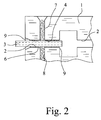
- Figs. 1 and 2 further show that at least one where the hollow fiber 3 is inserted is, is provided laterally from the channel 2 outgoing flow channel 8, can drain through the excess adhesive 6. So you can under pressure of the adhesive 6 dose this with excess and it is ensured that the drain channel 8 dissipates excess adhesive 6, so that the adhesive 6 does not reach and block the inner channel in the hollow fiber 3.
- the trough-like capillary stop structures 9 in the drawing can be smaller be executed, so have a smaller content, if you look at the angle at the end of the hollow fiber 3 over 90 ° out chooses, so returning "ear-like" Kapillarstoptrukturen 9 realized. Then it is even safer that there is no blockage of the inner channel of the hollow fiber 3 by adhesive.
- An alternative capillary stop structure 9 forms an extension or passageway in a mask or film on the microfluidic Network at the point at which the adhesive 6 in the capillary 4 um the hollow fiber 3 should remain.
- the inner diameter of the inner channel in the hollow fiber 3 should be between 5 microns and 450 microns, preferably between about 50 microns and about 250 microns, amount.
- a dialysis fiber as a hollow fiber 3 has a semi-permeable jacket, moreover, the Media exchange in the dialysis machine or in a metrological structure allowed.
- Preferred variants of the material for the hollow fiber are polymer material, a metal, such as stainless steel, glass or ceramic or cellulose.
- adhesive 6 in particular can use a UV-curable adhesive, the exact controlled its curing process starts and ends. If you have one used such adhesive 6, so you should the cover 5 or cover plate from a UV-transparent material.
- the glue 6 come z. As acrylates, urethanes, but also two-component epoxy resins in question.
- the cover 5 can z. As polycarbonate, polyester, Polystyrene or PVC made or produced on this basis be.
- the adhesive 6 is in the processing state have a viscosity of about 100 mPas to about 400 mPas should.
- the channel 2 is performed with a width that corresponds to about twice the depth and it allows two hollow fibers 3 in a channel 2 at the same time stick together.
- the same can also for a three-channel design or the like. be valid.
- Fig. 1 shows in this respect a preferred embodiment of the invention as several channels 2 of the network in which hollow fibers 3 are inserted, by at least one connecting channel 10 for the adhesive 6 with each other connected, the function of the drain channel for a channel 2 and the Function of the inlet channel for the other channel 2 met.
- capillary forces the side distribution takes place in the channels 2 with the hollow fibers. 3 until the capillary stop structures 9 stop.
- the entire assembly is in the horizontal orientation brought and then irradiated with UV radiation.
Landscapes
- Chemical & Material Sciences (AREA)
- Health & Medical Sciences (AREA)
- Chemical Kinetics & Catalysis (AREA)
- General Health & Medical Sciences (AREA)
- Dispersion Chemistry (AREA)
- Analytical Chemistry (AREA)
- Hematology (AREA)
- Clinical Laboratory Science (AREA)
- Organic Chemistry (AREA)
- Engineering & Computer Science (AREA)
- Microelectronics & Electronic Packaging (AREA)
- Physical Or Chemical Processes And Apparatus (AREA)
- Separation Using Semi-Permeable Membranes (AREA)
- Micromachines (AREA)
- External Artificial Organs (AREA)
Abstract
Description
- Fig. 1
- in einer perspektivischen, dreidimensional anmutenden Darstellung das Grundprinzip eines erfindungsgemäßen mikrofluidischen Systems,
- Fig. 2
- das mikrofluidische System aus Fig. 1 in einer Draufsicht.
Claims (33)
- Verfahren zum Koppeln mindestens einer mikrofluidischen Hohlfaser an ein mikrofluidisches Netzwerk,
wobei das mikrofluidische Netzwerk mindestens einen oberseitig offenen Kanal (2) aufweist, in dem die Hohlfaser (3) mit einem Ende eingelegt wird, und:dadurch gekennzeichnet, daß der noch flüssige Kleber (6) im Kanal (2) im Bereich des Endes der Hohlfaser (3) durch eine Kapillarstopstruktur (9) gestoppt wird.a) die Außenabmessungen, insbesondere der Außendurchmesser, der Hohlfaser (3) so auf die Innenabmessungen, insbesondere die Breite und die Tiefe des Kanals (2) abgestimmt werden, daß sich zwischen der Hohlfaser (3) und den Kanalwandungen, insbesondere in in den Winkeln verbleibenden Zwickeln, Kapillarkanäle (4) ergeben;b) das mikrofluidische Netzwerk bei im Kanal (2) einliegender Hohlfaser (3) mit einer Abdeckfolie oder -platte (5) abgedeckt wird, die auf dem Netzwerk fixiert wird und den Kanal (2) oberseitig schließt;c) durch mindestens einen in den Kanal (2) mündenden Zulaufkanal (7) im mikrofluidischen Netzwerk wird ein im Endzustand fluidisch dichtender, im Verarbeitungszustand flüssiger Kleber (6) in den Kanal (2) dort eingeleitet, wo die Hohlfaser (3) einliegt, so daß sich die Kapillarkanäle (4) um die Hohlfaser (3) herum füllen;d) nach Abschluß des Verfahrensschrittes d) wird der Kleber (6) in den Endzustand gebracht, insbesondere ausgehärtet, bzw. erreicht diesen; - Verfahren nach Anspruch 1, dadurch gekennzeichnet, daß durch mindestens einen vom Kanal (2) abgehenden Ablaufkanal (8) im mikrofluidischen Netzwerk überschüssiger Kleber (6) im Verarbeitungszustand aus dem Kanal (2) abgeleitet wird und/oder daß im Verfahrensschritt b) die Abdeckfolie oder -platte (5) die Hohlfaser (3) im Kanal (2) vorläufig fixiert.
- Verfahren nach Anspruch 1 oder 2, dadurch gekennzeichnet, daß die Kapillarstopstruktur (9) durch den Kanal (2) vorzugsweise stufenartig verbreiternde Wandabschnitte und/oder einen insbesondere stirnseitigen Absatz der Hohlfaserwandung gebildet wird.
- Verfahren nach einem der vorhergehenden Ansprüche, dadurch gekennzeichnet, daß die Abdeckfolie oder -platte (5) oder eine zusätzliche Folie oder Platte auf dem mikrofluidischen Netzwerk als Maske mit einer Durchlaßstelle an der Stelle, an der der Kleber (6) in den Kapillarkanälen (4) um die Hohlfaser (3) stehen bleiben soll, ausgeführt ist und daß während des Einleitens des Klebers (6) an der Durchlaßstelle eine solche Beeinflussung des Klebers (6) erfolgt, daß dieser hier seinen Endzustand erreicht.
- Verfahren nach einem der vorhergehenden Ansprüche, dadurch gekennzeichnet, daß etwa dort, wo die Hohlfaser (3) aus dem Kanal (2) nach außen austritt, im Kanal (2) jedenfalls die Wandabschnitte mit einer den Kanal (2) verbreiternden, vorzugsweise stufenartigen oder schräg verlaufenden Kapillarstopstruktur (9) versehen sind.
- Verfahren nach einem der vorhergehenden Ansprüche, dadurch gekennzeichnet, daß während des Einleitens des Klebers (6) in die Kapillarkanäle (4) um die Hohlfaser (3) das Fließen des Klebers (6) erfaßt, insbesondere beobachtet wird und dann, wenn der Kleber (6) eine Stelle erreicht, an der er stehen bleiben soll, der Kleber (6) in den Endzustand gebracht wird.
- Verfahren nach einem der vorhergehenden Ansprüche, dadurch gekennzeichnet, daß der Kanal (2) mit einer Breite und Tiefe von etwa 30 µm bis etwa 500 µm, vorzugsweise etwa 100 µm bis etwa 300 µm, ausgeführt wird und daß die Hohlfaser (3) mit darauf abgestimmten Abmessungen, insbesondere einem darauf abgestimmten Durchmesser, von etwa 30 µm bis etwa 500 µm, vorzugsweise etwa 100 µm bis etwa 300 µm, ausgeführt wird.
- Verfahren nach einem der vorhergehenden Ansprüche, dadurch gekennzeichnet, daß als Hohlfaser (3) eine Faser aus Polymermaterial, aus Metall, aus Glas, aus Keramik oder aus Cellulose verwendet wird und/oder daß als Hohlfaser (3) eine Dialysefaser verwendet wird.
- Verfahren nach einem der vorhergehenden Ansprüche, dadurch gekennzeichnet, daß als Kleber (6) ein flüssiger Klebstoff mit einer Viskosität von etwa 10 mPas bis etwa 600 mPas, vorzugsweise von etwa 100 mPas bis etwa 400 mPas, verwendet wird.
- Verfahren nach einem der vorhergehenden Ansprüche, dadurch gekennzeichnet, daß als Kleber (6) ein unter UV-Strahlung aushärtender Klebstoff verwendet und der Kleber (6) durch Bestrahlen mit UV-Strahlung in den Endzustand gebracht wird.
- Verfahren nach einem der vorhergehenden Ansprüche, dadurch gekennzeichnet, daß für die Abdeckfolie oder -platte (5) ein für UV-Strahlung durchlässiges Material verwendet wird.
- Verfahren nach einem der vorhergehenden Ansprüche, dadurch gekennzeichnet, daß der Kleber (6) quasi drucklos, also im wesentlichen nur unter Eigendruck des Klebervorrats, in den Kanal (2) eingeleitet wird.
- Verfahren nach einem der vorhergehenden Ansprüche, dadurch gekennzeichnet, daß das Einleiten des Klebers (6) in das Netzwerk bei im wesentlichen vertikaler Ausrichtung des Netzwerkes von oben aus erfolgt.
- Verfahren nach einem der vorhergehenden Ansprüche, dadurch gekennzeichnet, daß das Fixieren des Klebers (6), insbesondere das Aushärten des Klebers (6), bei im wesentlichen horizontaler Ausrichtung des Netzwerkes erfolgt.
- Verfahren nach einem der vorhergehenden Ansprüche, dadurch gekennzeichnet, daß der Kanal (2) mit einer Breite ausgeführt wird, die etwa dem Doppelten der Tiefe entspricht und es ermöglicht, zwei Hohlfasern (3) gleichzeitig in einem Kanal (2) zu verkleben.
- Verfahren nach einem der vorhergehenden Ansprüche, dadurch gekennzeichnet, daß mehrere Kanäle (2) des Netzwerkes, in die Hohlfasern (3) eingelegt werden, durch mindestens einen Verbindungskanal (10) für den Kleber (6) miteinander verbunden werden, der die Funktion des Ablaufkanals (8) für einen Kanal (2) und die Funktion des Zulaufkanals (7) für den anderen Kanal (2) erfüllt.
- Mikrofluidisches System aus einem mikrofluidischen Netzwerk mit einem Mikrostrukturträger (1) mit mindestens einem Kanal (2) und einer mit einem Ende im Kanal (2) eingelegten, stirnseitig in den Kanal (2) mündenden mikrofluidischen Hohlfaser (3),
wobei die Außenabmessungen, insbesondere der Außendurchmesser der Hohlfaser (3), so auf die Innenabmessungen, insbesondere die Breite und die Tiefe des Kanals (2), abgestimmt sind, daß zwischen der Hohlfaser (3) und den Wandungen des Kanals (2), insbesondere in in den Winkeln verbleibenden Zwickeln, Kapillarkanäle (4) vorliegen,
insbesondere wobei das Netzwerk mit einer auf dem Mikrostrukturträger (1) fixierten Abdeckfolie oder -platte (5) abgedeckt ist, die den Kanal (2) schließt, und
wobei die Kapillarkanäle (4) mit einem fluidisch dichtenden Kleber (6) ausgefüllt sind,
dadurch gekennzeichnet, daß im Bereich des Endes der Hohlfaser (3) im Kanal (2) eine Kapillarstopstruktur (9) vorgesehen ist, um ein Eindringen des Klebers (6) im flüssigen Zustand endseitig in die Hohlfaser (3) zu verhindern. - Mikrofluidisches System nach Anspruch 17, dadurch gekennzeichnet, daß die Abdeckfolie oder -platte (5) die Hohlfaser (3) im Kanal (2) vorläufig bis zum Einfüllen und Aushärten des Klebers (6) fixiert.
- Mikrofluidisches System nach Anspruch 17 oder 18, dadurch gekennzeichnet, daß die Kapillarstopstruktur (9) durch den Kanal (2) vorzugsweise stufenartig verbreiternde Wandabschnitte und/oder einen insbesondere stimseitigen Absatz der Hohlfaserwandung gebildet ist.
- Mikrofluidisches System nach einem der Ansprüche 17 bis 19, dadurch gekennzeichnet, daß die Kapillarstopstruktur (9) am inneren Ende eine beidseitige Stufe bildet.
- Mikrofluidisches System nach einem der Ansprüche 17 bis 20, dadurch gekennzeichnet, daß etwa dort, wo die Hohlfaser (3) aus dem Kanal (2) nach außen austritt, im Kanal (2) jedenfalls die Wandabschnitte mit einer den Kanal (2) verbreiternden, vorzugsweise stufenartigen oder schräg verlaufenden, äußeren Kapillarstopstruktur (9) ausgeführt sind.
- Mikrofluidisches System nach Anspruch 21, dadurch gekennzeichnet, daß die äußere Kapillarstopstruktur (9) am äußeren Ende des Kanals (2) eine trapezartige Erweiterung bildet.
- Mikrofluidisches System nach einem der Ansprüche 17 bis 22, dadurch gekennzeichnet, daß die Abdeckfolie oder -platte (5) oder eine zusätzliche Folie oder Platte auf dem mikrofluidischen Netzwerk als Maske mit einer Durchlaßstelle oder Erweiterung an der Stelle, an der der Kleber (6) in den Kapillarkanälen (4) um die Hohlfaser (3) stehen bleiben soll, ausgeführt ist.
- Mikrofluidisches System nach einem der Ansprüche 17 bis 23, dadurch gekennzeichnet, daß mindestens ein dort, wo die Hohlfaser (3) eingelegt ist, seitlich in den Kanal (2) mündender Zulaufkanal (7) vorgesehen ist, dessen anderes Ende eine Eintrittsstelle für den im Verarbeitungszustand flüssigen Kleber (6) bildet.
- Mikrofluidisches System nach einem der Ansprüche 17 bis 24, dadurch gekennzeichnet, daß mindestens ein dort, wo die Hohlfaser (3) eingelegt ist, seitlich vom Kanal (2) abgehender Ablaufkanal (8) vorgesehen ist, durch den überschüssiger Kleber (6) ablaufen kann.
- Mikrofluidisches System nach einem der Ansprüche 17 bis 25, dadurch gekennzeichnet, daß der Kanal (2) mit einer Breite und Tiefe von etwa 30 µm bis etwa 500 µm, vorzugsweise etwa 100 µm bis etwa 300 µm, ausgeführt ist und daß die Hohlfaser (3) mit darauf abgestimmten Abmessungen, insbesondere einem darauf abgestimmten Durchmesser, von etwa 30 µm bis etwa 500 µm, vorzugsweise etwa 100 µm bis etwa 300 µm, ausgeführt ist.
- Mikrofluidisches System nach einem der vorgehenden Vorrichtungsansprüche, dadurch gekennzeichnet, daß die Hohlfaser (3) eine Faser aus Polymermaterial, Metall, Glas, Keramik oder Cellulose ist und/oder daß die Hohlfaser (3) eine Dialysefaser ist.
- Mikrofluidisches System nach einem der Ansprüche 17 bis 27, dadurch gekennzeichnet, daß der Kleber (6) ein Klebstoff ist, der im flüssigen Verarbeitungszustand eine Viskosität von etwa 10 mPas bis etwa 600 mPas, vorzugsweise von etwa 100 mPas bis etwa 400 mPas, aufweist.
- Mikrofluidisches System nach einem der Ansprüche 17 bis 28, dadurch gekennzeichnet, daß der Kleber (6) ein unter UV-Strahlung ausgehärteter Kleber ist.
- Mikrofluidisches System nach einem der Ansprüche 17 bis 29, dadurch gekennzeichnet, daß die Abdeckfolie oder -platte (5) aus einem für Ultraviolett-Strahlung durchlässigen Material besteht, insbesondere wobei die Abdeckfolie (5) eine Heißsiegelfolie ist.
- Mikrofluidisches System nach einem der Ansprüche 17 bis 30, dadurch gekennzeichnet, daß der Kanal (2) mit einer Breite ausgeführt ist, die etwa dem Doppelten der Tiefe des Kanals (2) entspricht, und daß zwei Hohlfasern (3) gleichzeitig in einem Kanal (2) verklebt sind.
- Mikrofluidisches System nach einem der Ansprüche 17 bis 31, dadurch gekennzeichnet, daß mehrere Kanäle (2) des Netzwerks, in die Hohlfasern (3) eingelegt sind, durch mindestens einen Verbindungskanal (10) für den Kleber (6) miteinander verbunden sind, der die Funktion des Ablaufkanals für einen Kanal (2) und die Funktion des Zulaufkanals für den anderen Kanal (2) erfüllt.
- Mikrofluidisches System nach einem der Ansprüche 17 bis 32, dadurch gekennzeichnet, daß der Zulaufkanal (7) und/oder der Ablaufkanal (8) in einem rechten Winkel auf den Kanal (2) stößt bzw. stoßen.
Priority Applications (1)
| Application Number | Priority Date | Filing Date | Title |
|---|---|---|---|
| EP10010260A EP2258657A1 (de) | 2003-09-30 | 2004-09-18 | Verfahren und Vorrichtung zum Koppeln von Hohlfasern an ein mikrofluidisches Netzwerk |
Applications Claiming Priority (2)
| Application Number | Priority Date | Filing Date | Title |
|---|---|---|---|
| DE10345817 | 2003-09-30 | ||
| DE10345817A DE10345817A1 (de) | 2003-09-30 | 2003-09-30 | Verfahren und Vorrichtung zum Koppeln von Hohlfasern an ein mikrofluidisches Netzwerk |
Related Child Applications (1)
| Application Number | Title | Priority Date | Filing Date |
|---|---|---|---|
| EP10010260.7 Division-Into | 2010-09-23 |
Publications (2)
| Publication Number | Publication Date |
|---|---|
| EP1520838A1 true EP1520838A1 (de) | 2005-04-06 |
| EP1520838B1 EP1520838B1 (de) | 2012-02-22 |
Family
ID=34306208
Family Applications (2)
| Application Number | Title | Priority Date | Filing Date |
|---|---|---|---|
| EP04022269A Expired - Lifetime EP1520838B1 (de) | 2003-09-30 | 2004-09-18 | Verfahren und Vorrichtung zum Koppeln von Hohlfasern an ein mikrofluidisches Netzwerk |
| EP10010260A Withdrawn EP2258657A1 (de) | 2003-09-30 | 2004-09-18 | Verfahren und Vorrichtung zum Koppeln von Hohlfasern an ein mikrofluidisches Netzwerk |
Family Applications After (1)
| Application Number | Title | Priority Date | Filing Date |
|---|---|---|---|
| EP10010260A Withdrawn EP2258657A1 (de) | 2003-09-30 | 2004-09-18 | Verfahren und Vorrichtung zum Koppeln von Hohlfasern an ein mikrofluidisches Netzwerk |
Country Status (5)
| Country | Link |
|---|---|
| US (1) | US7638098B2 (de) |
| EP (2) | EP1520838B1 (de) |
| JP (1) | JP4851698B2 (de) |
| AT (1) | ATE546411T1 (de) |
| DE (1) | DE10345817A1 (de) |
Cited By (10)
| Publication number | Priority date | Publication date | Assignee | Title |
|---|---|---|---|---|
| NL1032425C2 (nl) * | 2006-09-04 | 2008-03-05 | Micronit Microfluidics Bv | Samenstel van ten minste één microfluïdische inrichting en een opzetstuk, opzetstuk en werkwijzen voor het vervaardigen en gebruik van zo een samenstel. |
| EP1925364A1 (de) * | 2006-11-23 | 2008-05-28 | Nederlandse Organisatie voor Toegepast-Natuuurwetenschappelijk Onderzoek TNO | Mikrofluidische Mehrfachverbindung |
| WO2008113112A1 (en) * | 2007-03-16 | 2008-09-25 | Cleveland Biosensors Pty Ltd | Stop structure for microfluidic device |
| EP2184103A1 (de) * | 2008-11-11 | 2010-05-12 | Onea Engineering Austria GmbH | Modularer Reaktor |
| WO2012007182A1 (de) * | 2010-07-16 | 2012-01-19 | Fraunhofer-Gesellschaft zur Förderung der angewandten Forschung e.V. | Mikrofluidisches system und herstellungsverfahren für ein mikrofluidisches system |
| DE102010043877B3 (de) * | 2010-11-12 | 2012-03-15 | Wyatt Technology Europe Gmbh | Hohlfaseranschluss |
| CN103132163A (zh) * | 2013-03-12 | 2013-06-05 | 东南大学 | 一种具有多重核壳结构的纤维及其制备方法 |
| CN106085846A (zh) * | 2015-03-09 | 2016-11-09 | Emd密理博公司 | 用于微流体系统中的气动装置的连接器 |
| CN112452251A (zh) * | 2020-10-27 | 2021-03-09 | 山东大学 | 月牙形及其变形陶瓷微颗粒、其制备方法、应用及制备装置 |
| US20240192641A1 (en) * | 2022-12-13 | 2024-06-13 | The Swatch Group Research And Development Ltd | Horological component resulting from the assembly of two parts and method for manufacturing said component |
Families Citing this family (25)
| Publication number | Priority date | Publication date | Assignee | Title |
|---|---|---|---|---|
| JP3933058B2 (ja) | 2002-02-25 | 2007-06-20 | 日立化成工業株式会社 | マイクロ流体システム用支持ユニット及びその製造方法 |
| US20050082470A1 (en) * | 2003-10-15 | 2005-04-21 | Dziekan Michael E. | Method of utilizing "Holey" optical fibers for a passive, miniature liquid feed/collection system |
| US20050117864A1 (en) * | 2003-12-01 | 2005-06-02 | Dziekan Michael E. | Method of synthesis and delivery of complex pharmaceuticals, chemical substances and polymers through the process of electrospraying, electrospinning or extrusion utilizing holey fibers |
| US20050249641A1 (en) * | 2004-04-08 | 2005-11-10 | Boehringer Ingelheim Microparts Gmbh | Microstructured platform and method for manipulating a liquid |
| WO2006059649A1 (ja) | 2004-11-30 | 2006-06-08 | Hitachi Chemical Co., Ltd. | 分析前処理用部品 |
| KR20070085991A (ko) * | 2004-12-09 | 2007-08-27 | 히다치 가세고교 가부시끼가이샤 | 마이크로 유체 시스템용 지지유닛 및 그 제조방법 |
| CN1987479A (zh) * | 2005-12-23 | 2007-06-27 | 博奥生物有限公司 | 阻止液体在亲水性微细管内沿管壁楔角流动的微流体腔体 |
| JP4852399B2 (ja) * | 2006-11-22 | 2012-01-11 | 富士フイルム株式会社 | 二液合流装置 |
| US20100218834A1 (en) * | 2007-01-30 | 2010-09-02 | Diramo A/S | Micro fluid device with a multi lumen hose |
| JP5267241B2 (ja) * | 2009-03-17 | 2013-08-21 | 住友ベークライト株式会社 | 流路デバイスの製造方法 |
| CN102482071B (zh) * | 2009-07-20 | 2015-07-29 | 莫纳什大学 | 三维微流体系统 |
| US10065403B2 (en) | 2009-11-23 | 2018-09-04 | Cyvek, Inc. | Microfluidic assay assemblies and methods of manufacture |
| US9651568B2 (en) | 2009-11-23 | 2017-05-16 | Cyvek, Inc. | Methods and systems for epi-fluorescent monitoring and scanning for microfluidic assays |
| US9500645B2 (en) | 2009-11-23 | 2016-11-22 | Cyvek, Inc. | Micro-tube particles for microfluidic assays and methods of manufacture |
| JP5250574B2 (ja) * | 2010-02-10 | 2013-07-31 | 富士フイルム株式会社 | マイクロ流路デバイス |
| CA2804564A1 (en) | 2010-07-09 | 2012-01-12 | Sophion Bioscience A/S | A chip assembly for use in a microfluidic analysis system |
| DE102010041833B4 (de) * | 2010-09-30 | 2014-05-15 | INSTITUT FüR MIKROTECHNIK MAINZ GMBH | Mikrofluidikchip mit mehreren Zylinder-Kolben-Anordnungen |
| CN103649759B (zh) * | 2011-03-22 | 2016-08-31 | 西维克公司 | 微流体装置以及制造方法和用途 |
| US9498753B2 (en) * | 2012-03-15 | 2016-11-22 | Koch Membrane Systems, Inc. | Method for sealing hollow fiber membranes |
| DE102012021603A1 (de) * | 2012-06-28 | 2014-01-23 | Philipp Comanns | Strukturierung bzw. Anordnung von Oberflächen zum gerichteten Transport von Flüssigkeiten in Kapillaren |
| US10228367B2 (en) | 2015-12-01 | 2019-03-12 | ProteinSimple | Segmented multi-use automated assay cartridge |
| WO2018067614A1 (en) * | 2016-10-04 | 2018-04-12 | Massachusetts Institute Of Technology | Fiber microfluidics |
| CN113941382B (zh) * | 2021-09-13 | 2022-10-11 | 杭州电子科技大学 | 一种利用碳纤维束抓取与释放液滴的方法与装置 |
| DE102021131435B4 (de) | 2021-11-30 | 2024-03-14 | Pierburg Gmbh | Elektromotor |
| CN116037227B (zh) * | 2022-11-02 | 2025-12-23 | 南京鼓楼医院 | 一种可集成纤维的多层多通道微流控芯片、制备方法及应用 |
Citations (4)
| Publication number | Priority date | Publication date | Assignee | Title |
|---|---|---|---|---|
| WO1997029394A1 (en) * | 1996-02-08 | 1997-08-14 | Northern Telecom Limited | Securing an optical fibre in a v-groove |
| WO1998025065A1 (en) * | 1996-12-07 | 1998-06-11 | Central Research Laboratories Limited | Fluid connections |
| WO2001086154A1 (en) * | 2000-05-12 | 2001-11-15 | Central Research Laboratories Limited | Method of forming a fluid tight seal |
| FR2813073A1 (fr) * | 2000-12-19 | 2002-02-22 | Commissariat Energie Atomique | Dispositif de positionnement et de guidage pour la connexion etanche de capillaires a un micro-composant |
Family Cites Families (2)
| Publication number | Priority date | Publication date | Assignee | Title |
|---|---|---|---|---|
| DE3408783A1 (de) * | 1983-08-03 | 1985-02-14 | Siemens AG, 1000 Berlin und 8000 München | Verbindungselement fuer lichtwellenleiter und verfahren zur herstellung |
| US5942112A (en) * | 1997-10-17 | 1999-08-24 | Ishak; Noshi A. | Hollow fiber ultradialyzer apparatus |
-
2003
- 2003-09-30 DE DE10345817A patent/DE10345817A1/de not_active Ceased
-
2004
- 2004-09-18 AT AT04022269T patent/ATE546411T1/de active
- 2004-09-18 EP EP04022269A patent/EP1520838B1/de not_active Expired - Lifetime
- 2004-09-18 EP EP10010260A patent/EP2258657A1/de not_active Withdrawn
- 2004-09-29 JP JP2004285434A patent/JP4851698B2/ja not_active Expired - Lifetime
- 2004-09-30 US US10/953,064 patent/US7638098B2/en active Active
Patent Citations (4)
| Publication number | Priority date | Publication date | Assignee | Title |
|---|---|---|---|---|
| WO1997029394A1 (en) * | 1996-02-08 | 1997-08-14 | Northern Telecom Limited | Securing an optical fibre in a v-groove |
| WO1998025065A1 (en) * | 1996-12-07 | 1998-06-11 | Central Research Laboratories Limited | Fluid connections |
| WO2001086154A1 (en) * | 2000-05-12 | 2001-11-15 | Central Research Laboratories Limited | Method of forming a fluid tight seal |
| FR2813073A1 (fr) * | 2000-12-19 | 2002-02-22 | Commissariat Energie Atomique | Dispositif de positionnement et de guidage pour la connexion etanche de capillaires a un micro-composant |
Cited By (20)
| Publication number | Priority date | Publication date | Assignee | Title |
|---|---|---|---|---|
| NL1032425C2 (nl) * | 2006-09-04 | 2008-03-05 | Micronit Microfluidics Bv | Samenstel van ten minste één microfluïdische inrichting en een opzetstuk, opzetstuk en werkwijzen voor het vervaardigen en gebruik van zo een samenstel. |
| WO2008030088A2 (en) | 2006-09-04 | 2008-03-13 | Micronit Microfluidics B.V. | Assembly of at least one microfluidic device and a mounting piece, mounting piece and methods for manufacture and use of such an assembly |
| WO2008030088A3 (en) * | 2006-09-04 | 2008-07-03 | Micronit Microfluidics Bv | Assembly of at least one microfluidic device and a mounting piece, mounting piece and methods for manufacture and use of such an assembly |
| US9387475B2 (en) | 2006-09-04 | 2016-07-12 | Micronit Microfluidics B.V. | Assembly of at least one microfluidic device and mounting piece |
| EP1925364A1 (de) * | 2006-11-23 | 2008-05-28 | Nederlandse Organisatie voor Toegepast-Natuuurwetenschappelijk Onderzoek TNO | Mikrofluidische Mehrfachverbindung |
| WO2008063070A1 (en) * | 2006-11-23 | 2008-05-29 | Nederlandse Organisatie Voor Toegepast-Natuurwetenschappelijk Onderzoek Tno | Multiple microfluidic connector |
| WO2008113112A1 (en) * | 2007-03-16 | 2008-09-25 | Cleveland Biosensors Pty Ltd | Stop structure for microfluidic device |
| EP2184103A1 (de) * | 2008-11-11 | 2010-05-12 | Onea Engineering Austria GmbH | Modularer Reaktor |
| WO2010055034A1 (de) * | 2008-11-11 | 2010-05-20 | Onea-Engineering Austria Gmbh | Modularer reaktor |
| US9101903B2 (en) | 2008-11-11 | 2015-08-11 | Onea-Engineering Austria Gmbh | Modular reactor |
| USRE48466E1 (en) | 2008-11-11 | 2021-03-16 | Onea-Engineering Austria Gmbh | Modular reactor |
| WO2012007182A1 (de) * | 2010-07-16 | 2012-01-19 | Fraunhofer-Gesellschaft zur Förderung der angewandten Forschung e.V. | Mikrofluidisches system und herstellungsverfahren für ein mikrofluidisches system |
| DE102010043877B3 (de) * | 2010-11-12 | 2012-03-15 | Wyatt Technology Europe Gmbh | Hohlfaseranschluss |
| EP2453231A3 (de) * | 2010-11-12 | 2014-02-19 | Wyatt Technology Europe Gmbh | Hohlfaseranschluss |
| CN103132163A (zh) * | 2013-03-12 | 2013-06-05 | 东南大学 | 一种具有多重核壳结构的纤维及其制备方法 |
| CN103132163B (zh) * | 2013-03-12 | 2016-01-27 | 东南大学 | 一种具有多重核壳结构的纤维的制备方法 |
| CN106085846A (zh) * | 2015-03-09 | 2016-11-09 | Emd密理博公司 | 用于微流体系统中的气动装置的连接器 |
| CN106085846B (zh) * | 2015-03-09 | 2019-02-01 | Emd密理博公司 | 用于微流体系统中的气动装置的连接器 |
| CN112452251A (zh) * | 2020-10-27 | 2021-03-09 | 山东大学 | 月牙形及其变形陶瓷微颗粒、其制备方法、应用及制备装置 |
| US20240192641A1 (en) * | 2022-12-13 | 2024-06-13 | The Swatch Group Research And Development Ltd | Horological component resulting from the assembly of two parts and method for manufacturing said component |
Also Published As
| Publication number | Publication date |
|---|---|
| JP4851698B2 (ja) | 2012-01-11 |
| US20050106752A1 (en) | 2005-05-19 |
| EP1520838B1 (de) | 2012-02-22 |
| EP2258657A1 (de) | 2010-12-08 |
| DE10345817A1 (de) | 2005-05-25 |
| US7638098B2 (en) | 2009-12-29 |
| JP2005103750A (ja) | 2005-04-21 |
| ATE546411T1 (de) | 2012-03-15 |
Similar Documents
| Publication | Publication Date | Title |
|---|---|---|
| EP1520838B1 (de) | Verfahren und Vorrichtung zum Koppeln von Hohlfasern an ein mikrofluidisches Netzwerk | |
| EP1419818B1 (de) | Vorrichtung zum schrittweisen Transport von Flüssigkeit unter Ausnutzung von Kapillarkräften | |
| EP2962758B1 (de) | Flusszelle mit einem speicherbereich und einem an einer sollbruchstelle aufschliessbaren transportkanal | |
| EP1685900B1 (de) | Verwendung einer Vorrichtung zur Untersuchung von Probenflüssigkeit | |
| DE102009024048B3 (de) | Montier- und demontierbares Mikrofluidiksystem und Verfahren zur Flutung des Systems | |
| EP2354566B1 (de) | Verfahren zur Herstellung einer Klebeverbindung sowie Anordnung zur Durchführung des Verfahrens | |
| EP2429758B1 (de) | Vorrichtung und verfahren zum fixieren eines bauteils an einem bauteilträger | |
| EP2428137A1 (de) | Beschlag | |
| DE4217553A1 (de) | Verfahren und Vorrichtung zum Ankoppeln von lichtleitenden Fasern für optische Signale der Nachrichtentechnik oder Sensorik an eine integriert-optische Komponente | |
| EP2368049B1 (de) | Beschlag | |
| DE2844523A1 (de) | Bewaesserungseinrichtung | |
| EP2552586B1 (de) | Bauteil eines biosensors und verfahren zur herstellung | |
| EP2593231B1 (de) | Mikrofluidisches system und herstellungsverfahren für ein mikrofluidisches system | |
| DE102007020418A1 (de) | Verfahren und Vorrichtung zum Herstellen eines Lichtleitkörpers sowie ein Lichtleitkörper | |
| EP2729251B1 (de) | Mikrofluidische struktur mit vertiefungen | |
| DE102006025477A1 (de) | Küvette | |
| DE102011005378A1 (de) | Optoelektronische Vorrichtung | |
| DE19607820A1 (de) | Vorrichtung zum Verbinden von zwei Profilen | |
| DE102008064620A1 (de) | Verfahren und Vorrichtung zur Herstellung eines Solarmoduls und solches Solarmodul | |
| DE102011005380A1 (de) | Optoelektronische Vorrichtung | |
| EP3891353B1 (de) | Verfahren und vorrichtung zum herstellen von thermoplastischen abstandhaltern | |
| DE102004033440A1 (de) | Mikrostrukturierte Vorrichtung und Verfahren zu ihrer Herstellung | |
| WO2022058181A1 (de) | Vorrichtung zum temperieren eines bauteils und herstellungsverfahren der vorrichtung | |
| DE19850041A1 (de) | Mikrotechnologisches Bondverfahren und zugehörige Vorrichtung | |
| DE102005003961A1 (de) | Vorrichtung und Verfahren zur Untersuchung von Probenflüssigkeit |
Legal Events
| Date | Code | Title | Description |
|---|---|---|---|
| PUAI | Public reference made under article 153(3) epc to a published international application that has entered the european phase |
Free format text: ORIGINAL CODE: 0009012 |
|
| AK | Designated contracting states |
Kind code of ref document: A1 Designated state(s): AT BE BG CH CY CZ DE DK EE ES FI FR GB GR HU IE IT LI LU MC NL PL PT RO SE SI SK TR |
|
| AX | Request for extension of the european patent |
Extension state: AL HR LT LV MK |
|
| 17P | Request for examination filed |
Effective date: 20050907 |
|
| AKX | Designation fees paid |
Designated state(s): AT BE BG CH CY CZ DE DK EE ES FI FR GB GR HU IE IT LI LU MC NL PL PT RO SE SI SK TR |
|
| RIC1 | Information provided on ipc code assigned before grant |
Ipc: B01L 3/00 20060101ALI20071011BHEP Ipc: B81C 3/00 20060101AFI20071011BHEP Ipc: F16L 13/11 20060101ALI20071011BHEP |
|
| GRAP | Despatch of communication of intention to grant a patent |
Free format text: ORIGINAL CODE: EPIDOSNIGR1 |
|
| GRAS | Grant fee paid |
Free format text: ORIGINAL CODE: EPIDOSNIGR3 |
|
| GRAA | (expected) grant |
Free format text: ORIGINAL CODE: 0009210 |
|
| AK | Designated contracting states |
Kind code of ref document: B1 Designated state(s): AT BE BG CH CY CZ DE DK EE ES FI FR GB GR HU IE IT LI LU MC NL PL PT RO SE SI SK TR |
|
| REG | Reference to a national code |
Ref country code: GB Ref legal event code: FG4D Free format text: NOT ENGLISH |
|
| REG | Reference to a national code |
Ref country code: CH Ref legal event code: EP |
|
| REG | Reference to a national code |
Ref country code: AT Ref legal event code: REF Ref document number: 546411 Country of ref document: AT Kind code of ref document: T Effective date: 20120315 |
|
| REG | Reference to a national code |
Ref country code: IE Ref legal event code: FG4D Free format text: LANGUAGE OF EP DOCUMENT: GERMAN |
|
| REG | Reference to a national code |
Ref country code: DE Ref legal event code: R096 Ref document number: 502004013309 Country of ref document: DE Effective date: 20120419 |
|
| REG | Reference to a national code |
Ref country code: NL Ref legal event code: VDEP Effective date: 20120222 |
|
| PG25 | Lapsed in a contracting state [announced via postgrant information from national office to epo] |
Ref country code: NL Free format text: LAPSE BECAUSE OF FAILURE TO SUBMIT A TRANSLATION OF THE DESCRIPTION OR TO PAY THE FEE WITHIN THE PRESCRIBED TIME-LIMIT Effective date: 20120222 |
|
| PG25 | Lapsed in a contracting state [announced via postgrant information from national office to epo] |
Ref country code: FI Free format text: LAPSE BECAUSE OF FAILURE TO SUBMIT A TRANSLATION OF THE DESCRIPTION OR TO PAY THE FEE WITHIN THE PRESCRIBED TIME-LIMIT Effective date: 20120222 Ref country code: PT Free format text: LAPSE BECAUSE OF FAILURE TO SUBMIT A TRANSLATION OF THE DESCRIPTION OR TO PAY THE FEE WITHIN THE PRESCRIBED TIME-LIMIT Effective date: 20120622 Ref country code: GR Free format text: LAPSE BECAUSE OF FAILURE TO SUBMIT A TRANSLATION OF THE DESCRIPTION OR TO PAY THE FEE WITHIN THE PRESCRIBED TIME-LIMIT Effective date: 20120523 |
|
| REG | Reference to a national code |
Ref country code: IE Ref legal event code: FD4D |
|
| PG25 | Lapsed in a contracting state [announced via postgrant information from national office to epo] |
Ref country code: CY Free format text: LAPSE BECAUSE OF FAILURE TO SUBMIT A TRANSLATION OF THE DESCRIPTION OR TO PAY THE FEE WITHIN THE PRESCRIBED TIME-LIMIT Effective date: 20120222 |
|
| PG25 | Lapsed in a contracting state [announced via postgrant information from national office to epo] |
Ref country code: DK Free format text: LAPSE BECAUSE OF FAILURE TO SUBMIT A TRANSLATION OF THE DESCRIPTION OR TO PAY THE FEE WITHIN THE PRESCRIBED TIME-LIMIT Effective date: 20120222 Ref country code: RO Free format text: LAPSE BECAUSE OF FAILURE TO SUBMIT A TRANSLATION OF THE DESCRIPTION OR TO PAY THE FEE WITHIN THE PRESCRIBED TIME-LIMIT Effective date: 20120222 Ref country code: EE Free format text: LAPSE BECAUSE OF FAILURE TO SUBMIT A TRANSLATION OF THE DESCRIPTION OR TO PAY THE FEE WITHIN THE PRESCRIBED TIME-LIMIT Effective date: 20120222 Ref country code: CZ Free format text: LAPSE BECAUSE OF FAILURE TO SUBMIT A TRANSLATION OF THE DESCRIPTION OR TO PAY THE FEE WITHIN THE PRESCRIBED TIME-LIMIT Effective date: 20120222 Ref country code: PL Free format text: LAPSE BECAUSE OF FAILURE TO SUBMIT A TRANSLATION OF THE DESCRIPTION OR TO PAY THE FEE WITHIN THE PRESCRIBED TIME-LIMIT Effective date: 20120222 Ref country code: SI Free format text: LAPSE BECAUSE OF FAILURE TO SUBMIT A TRANSLATION OF THE DESCRIPTION OR TO PAY THE FEE WITHIN THE PRESCRIBED TIME-LIMIT Effective date: 20120222 Ref country code: IE Free format text: LAPSE BECAUSE OF FAILURE TO SUBMIT A TRANSLATION OF THE DESCRIPTION OR TO PAY THE FEE WITHIN THE PRESCRIBED TIME-LIMIT Effective date: 20120222 Ref country code: SE Free format text: LAPSE BECAUSE OF FAILURE TO SUBMIT A TRANSLATION OF THE DESCRIPTION OR TO PAY THE FEE WITHIN THE PRESCRIBED TIME-LIMIT Effective date: 20120222 |
|
| PG25 | Lapsed in a contracting state [announced via postgrant information from national office to epo] |
Ref country code: IT Free format text: LAPSE BECAUSE OF FAILURE TO SUBMIT A TRANSLATION OF THE DESCRIPTION OR TO PAY THE FEE WITHIN THE PRESCRIBED TIME-LIMIT Effective date: 20120222 Ref country code: SK Free format text: LAPSE BECAUSE OF FAILURE TO SUBMIT A TRANSLATION OF THE DESCRIPTION OR TO PAY THE FEE WITHIN THE PRESCRIBED TIME-LIMIT Effective date: 20120222 |
|
| PLBE | No opposition filed within time limit |
Free format text: ORIGINAL CODE: 0009261 |
|
| STAA | Information on the status of an ep patent application or granted ep patent |
Free format text: STATUS: NO OPPOSITION FILED WITHIN TIME LIMIT |
|
| 26N | No opposition filed |
Effective date: 20121123 |
|
| REG | Reference to a national code |
Ref country code: DE Ref legal event code: R097 Ref document number: 502004013309 Country of ref document: DE Effective date: 20121123 |
|
| BERE | Be: lapsed |
Owner name: BOEHRINGER INGELHEIM MICROPARTS G.M.B.H. Effective date: 20120930 |
|
| PG25 | Lapsed in a contracting state [announced via postgrant information from national office to epo] |
Ref country code: ES Free format text: LAPSE BECAUSE OF FAILURE TO SUBMIT A TRANSLATION OF THE DESCRIPTION OR TO PAY THE FEE WITHIN THE PRESCRIBED TIME-LIMIT Effective date: 20120602 Ref country code: MC Free format text: LAPSE BECAUSE OF NON-PAYMENT OF DUE FEES Effective date: 20120930 |
|
| REG | Reference to a national code |
Ref country code: CH Ref legal event code: PL |
|
| PG25 | Lapsed in a contracting state [announced via postgrant information from national office to epo] |
Ref country code: CH Free format text: LAPSE BECAUSE OF NON-PAYMENT OF DUE FEES Effective date: 20120930 Ref country code: BE Free format text: LAPSE BECAUSE OF NON-PAYMENT OF DUE FEES Effective date: 20120930 Ref country code: BG Free format text: LAPSE BECAUSE OF FAILURE TO SUBMIT A TRANSLATION OF THE DESCRIPTION OR TO PAY THE FEE WITHIN THE PRESCRIBED TIME-LIMIT Effective date: 20120522 Ref country code: LI Free format text: LAPSE BECAUSE OF NON-PAYMENT OF DUE FEES Effective date: 20120930 |
|
| REG | Reference to a national code |
Ref country code: AT Ref legal event code: MM01 Ref document number: 546411 Country of ref document: AT Kind code of ref document: T Effective date: 20120918 |
|
| PG25 | Lapsed in a contracting state [announced via postgrant information from national office to epo] |
Ref country code: AT Free format text: LAPSE BECAUSE OF NON-PAYMENT OF DUE FEES Effective date: 20120918 |
|
| PG25 | Lapsed in a contracting state [announced via postgrant information from national office to epo] |
Ref country code: TR Free format text: LAPSE BECAUSE OF FAILURE TO SUBMIT A TRANSLATION OF THE DESCRIPTION OR TO PAY THE FEE WITHIN THE PRESCRIBED TIME-LIMIT Effective date: 20120222 |
|
| PG25 | Lapsed in a contracting state [announced via postgrant information from national office to epo] |
Ref country code: LU Free format text: LAPSE BECAUSE OF NON-PAYMENT OF DUE FEES Effective date: 20120918 |
|
| PG25 | Lapsed in a contracting state [announced via postgrant information from national office to epo] |
Ref country code: HU Free format text: LAPSE BECAUSE OF FAILURE TO SUBMIT A TRANSLATION OF THE DESCRIPTION OR TO PAY THE FEE WITHIN THE PRESCRIBED TIME-LIMIT Effective date: 20040918 |
|
| REG | Reference to a national code |
Ref country code: FR Ref legal event code: PLFP Year of fee payment: 13 |
|
| REG | Reference to a national code |
Ref country code: FR Ref legal event code: PLFP Year of fee payment: 14 |
|
| REG | Reference to a national code |
Ref country code: FR Ref legal event code: PLFP Year of fee payment: 15 |
|
| PGFP | Annual fee paid to national office [announced via postgrant information from national office to epo] |
Ref country code: GB Payment date: 20230920 Year of fee payment: 20 |
|
| PGFP | Annual fee paid to national office [announced via postgrant information from national office to epo] |
Ref country code: FR Payment date: 20230927 Year of fee payment: 20 Ref country code: DE Payment date: 20230920 Year of fee payment: 20 |
|
| REG | Reference to a national code |
Ref country code: DE Ref legal event code: R071 Ref document number: 502004013309 Country of ref document: DE |
|
| REG | Reference to a national code |
Ref country code: GB Ref legal event code: PE20 Expiry date: 20240917 |
|
| PG25 | Lapsed in a contracting state [announced via postgrant information from national office to epo] |
Ref country code: GB Free format text: LAPSE BECAUSE OF EXPIRATION OF PROTECTION Effective date: 20240917 |
|
| PG25 | Lapsed in a contracting state [announced via postgrant information from national office to epo] |
Ref country code: GB Free format text: LAPSE BECAUSE OF EXPIRATION OF PROTECTION Effective date: 20240917 |