EP1520717B1 - Tintenstrahlaufzeichnungsgerät und Regelungsverfahren eines vorgenannten Gerätes - Google Patents
Tintenstrahlaufzeichnungsgerät und Regelungsverfahren eines vorgenannten Gerätes Download PDFInfo
- Publication number
- EP1520717B1 EP1520717B1 EP04255966A EP04255966A EP1520717B1 EP 1520717 B1 EP1520717 B1 EP 1520717B1 EP 04255966 A EP04255966 A EP 04255966A EP 04255966 A EP04255966 A EP 04255966A EP 1520717 B1 EP1520717 B1 EP 1520717B1
- Authority
- EP
- European Patent Office
- Prior art keywords
- recording
- ink
- recording medium
- information
- time
- Prior art date
- Legal status (The legal status is an assumption and is not a legal conclusion. Google has not performed a legal analysis and makes no representation as to the accuracy of the status listed.)
- Expired - Lifetime
Links
- 238000000034 method Methods 0.000 title claims description 25
- 230000007613 environmental effect Effects 0.000 claims description 17
- 238000007599 discharging Methods 0.000 claims description 6
- 239000000976 ink Substances 0.000 description 156
- 239000000123 paper Substances 0.000 description 51
- 238000001035 drying Methods 0.000 description 37
- 230000002401 inhibitory effect Effects 0.000 description 22
- 239000000049 pigment Substances 0.000 description 19
- 230000008569 process Effects 0.000 description 18
- 230000000875 corresponding effect Effects 0.000 description 17
- 238000001514 detection method Methods 0.000 description 12
- 238000007639 printing Methods 0.000 description 12
- 230000006870 function Effects 0.000 description 8
- 230000008859 change Effects 0.000 description 7
- 238000004140 cleaning Methods 0.000 description 7
- 239000001041 dye based ink Substances 0.000 description 7
- 230000004044 response Effects 0.000 description 7
- 239000007787 solid Substances 0.000 description 7
- 238000012937 correction Methods 0.000 description 6
- 230000035515 penetration Effects 0.000 description 6
- 230000002829 reductive effect Effects 0.000 description 6
- 238000000926 separation method Methods 0.000 description 6
- 210000000078 claw Anatomy 0.000 description 5
- 230000007423 decrease Effects 0.000 description 5
- 230000005540 biological transmission Effects 0.000 description 4
- 230000000694 effects Effects 0.000 description 4
- 230000005764 inhibitory process Effects 0.000 description 4
- 239000001042 pigment based ink Substances 0.000 description 4
- 238000012546 transfer Methods 0.000 description 4
- 230000008030 elimination Effects 0.000 description 3
- 238000003379 elimination reaction Methods 0.000 description 3
- 230000000149 penetrating effect Effects 0.000 description 3
- 230000002441 reversible effect Effects 0.000 description 3
- 239000000758 substrate Substances 0.000 description 3
- 230000008901 benefit Effects 0.000 description 2
- 238000004364 calculation method Methods 0.000 description 2
- 238000006243 chemical reaction Methods 0.000 description 2
- 239000003086 colorant Substances 0.000 description 2
- 230000006866 deterioration Effects 0.000 description 2
- 230000006872 improvement Effects 0.000 description 2
- 238000002347 injection Methods 0.000 description 2
- 239000007924 injection Substances 0.000 description 2
- 238000007641 inkjet printing Methods 0.000 description 2
- 230000010354 integration Effects 0.000 description 2
- 238000002156 mixing Methods 0.000 description 2
- 238000001454 recorded image Methods 0.000 description 2
- 230000000717 retained effect Effects 0.000 description 2
- 238000003860 storage Methods 0.000 description 2
- 230000009471 action Effects 0.000 description 1
- 239000007864 aqueous solution Substances 0.000 description 1
- 238000009835 boiling Methods 0.000 description 1
- 238000010276 construction Methods 0.000 description 1
- 230000008602 contraction Effects 0.000 description 1
- 230000001276 controlling effect Effects 0.000 description 1
- 230000002596 correlated effect Effects 0.000 description 1
- 230000001186 cumulative effect Effects 0.000 description 1
- 230000003247 decreasing effect Effects 0.000 description 1
- 230000000593 degrading effect Effects 0.000 description 1
- 238000010586 diagram Methods 0.000 description 1
- 239000006185 dispersion Substances 0.000 description 1
- 239000000428 dust Substances 0.000 description 1
- 238000005516 engineering process Methods 0.000 description 1
- 239000002649 leather substitute Substances 0.000 description 1
- 238000012423 maintenance Methods 0.000 description 1
- 230000007257 malfunction Effects 0.000 description 1
- 238000004519 manufacturing process Methods 0.000 description 1
- 239000000463 material Substances 0.000 description 1
- 239000012528 membrane Substances 0.000 description 1
- 239000000203 mixture Substances 0.000 description 1
- 238000012986 modification Methods 0.000 description 1
- 230000004048 modification Effects 0.000 description 1
- 230000003287 optical effect Effects 0.000 description 1
- 239000002985 plastic film Substances 0.000 description 1
- 238000003825 pressing Methods 0.000 description 1
- 230000009467 reduction Effects 0.000 description 1
- 239000000243 solution Substances 0.000 description 1
- XLYOFNOQVPJJNP-UHFFFAOYSA-N water Substances O XLYOFNOQVPJJNP-UHFFFAOYSA-N 0.000 description 1
Images


Classifications
-
- B—PERFORMING OPERATIONS; TRANSPORTING
- B41—PRINTING; LINING MACHINES; TYPEWRITERS; STAMPS
- B41J—TYPEWRITERS; SELECTIVE PRINTING MECHANISMS, i.e. MECHANISMS PRINTING OTHERWISE THAN FROM A FORME; CORRECTION OF TYPOGRAPHICAL ERRORS
- B41J3/00—Typewriters or selective printing or marking mechanisms characterised by the purpose for which they are constructed
- B41J3/60—Typewriters or selective printing or marking mechanisms characterised by the purpose for which they are constructed for printing on both faces of the printing material
-
- B—PERFORMING OPERATIONS; TRANSPORTING
- B41—PRINTING; LINING MACHINES; TYPEWRITERS; STAMPS
- B41J—TYPEWRITERS; SELECTIVE PRINTING MECHANISMS, i.e. MECHANISMS PRINTING OTHERWISE THAN FROM A FORME; CORRECTION OF TYPOGRAPHICAL ERRORS
- B41J13/00—Devices or arrangements of selective printing mechanisms, e.g. ink-jet printers or thermal printers, specially adapted for supporting or handling copy material in short lengths, e.g. sheets
- B41J13/0009—Devices or arrangements of selective printing mechanisms, e.g. ink-jet printers or thermal printers, specially adapted for supporting or handling copy material in short lengths, e.g. sheets control of the transport of the copy material
- B41J13/0045—Devices or arrangements of selective printing mechanisms, e.g. ink-jet printers or thermal printers, specially adapted for supporting or handling copy material in short lengths, e.g. sheets control of the transport of the copy material concerning sheet refeed sections of automatic paper handling systems, e.g. intermediate stackers
Definitions
- the present invention relates to an ink-jet recording apparatus which performs recording by discharging ink on a recording medium and a control method thereof. More particularly, the invention relates to an ink-jet recording apparatus which permits recording on two surfaces of the recording medium and a control method thereof.
- Recording apparatuses recording images comprising dot patterns on a recording medium such as paper and a plastic sheet on the basis of recording information are generally known as applicable to printers, copying machines and facsimile machines.
- Types of recording for forming an image comprising dot patterns as described above include the ink-jet type, the wire dot type, the thermal type and the laser beam type.
- the ink-jet type discharges and ejects ink (recording solution) drops from a discharge port of a recording head, and causes adhesion thereof to a recording medium, thereby accomplishing recording.
- This type can therefore provide an advantage of allowing construction at a relatively low cost.
- this ink-jet type which uses ink composed of an aqueous solution, in order to ensure sufficient fixing of the recorded image, it is necessary to vaporize the water content of the ink discharged onto the recording medium, thus requiring some time (fixing time).
- the insufficiently dried ink adheres to the back of the next recording medium, thus causing a feat of image deterioration on the previously discharged recording medium discharged in advance, and of an occurrence of smears in which the back of the recording media discharged next is stained.
- a smear may also be produced when automatically performing recording on two surfaces of the recording medium. That is, in an ink-jet recording apparatus having a double-sided recording function, after performing recording on one of the surfaces of the recording medium (hereinafter referred to as the "surface” or the “first recorded surface”), the recording medium is fed again into a conveyance path for reversing. The recording medium is reversed here, and the recording operation is applied to the other surface thereof (hereinafter referred to as the "back” or the "second recorded surface”). This leads to re-introduction of the insufficiently dried recording medium into the conveyance path for reversing.
- the recording medium is rubbed against the conveyance path for reversing, resulting in occurrence of smears including the degrading of the recorded image, and furthermore, the thus produced smears cause another inconvenience of an occurrence of secondary smears in which the above-mentioned smears cause the ink adhering in the conveyance path to be transferred to the next recording medium.
- the drying period should preferably be the shortest possible.
- An apparatus for inhibiting ink stains by setting a drying period in response to the number of ink application runs to the entire area of one of the surfaces of the recording medium, without providing an excessive drying period has been proposed (for example, see the US Patent No. 6,149,327 specification).
- the ink-jet printing apparatus determines, based on an amount of ink discharged onto a most recently printed printing medium, a time delay before discharge of the printing medium.
- US2002/0024574 discloses an image recording apparatus for printing on both sides of a recording medium. The image recording apparatus is arranged to provide a delay between printing on a first side of the printing medium and printing on a reverse side of the recording medium.
- the present invention was developed to solve the above-mentioned problems and has an object to provide an ink-jet recording apparatus which enables, in an ink-jet recording apparatus permitting two-side recording, to inhibit smears occurring by contact of the recording medium with the conveyance path, or secondary smears which stain the next and subsequent recording media by the ink adhering to the conveyance path, and to reduce the drying time provided for such inhibition as far as possible, and a control method of this apparatus.
- the operation is in a stopped state.
- This period may hereafter sometimes be referred to as an operation downtime.
- the above-mentioned period is provided for drying (or fixing) the ink recorded on the surface. Therefore, the above-mentioned period may sometimes be referred to as a drying time (or the fixing time).
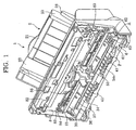
- Fig. 1 is a perspective view illustrating the whole configuration view of the ink-jet recording apparatus in an embodiment of the present invention
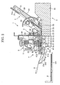
- Fig. 2 is a side sectional view of the ink-jet recording apparatus in the embodiment of the present invention.
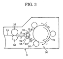
- Fig. 3 is a descriptive side view illustrating a schematic configuration of a recording medium reversing section in the embodiment of the present invention
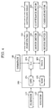
- Fig. 4 is a block diagram schematically illustrating the configuration of the control system of the ink-jet recording apparatus in the embodiment of the present invention
- Fig. 5 illustrates a dot count region corresponding to the unit region to be subjected to dot counting
- Figs. 6A and 6B cover descriptive view illustrating the positional relationship between the dot count region W and an actual recorded region R: Fig. 6A relates to a case where the recorded region R and the dot count region W are in agreement; and Fig. 6B relates to a case where the recorded region R and the dust count region are not in agreement;
- Fig. 7 is a descriptive view illustrating a plurality of control regions obtained by dividing the regions on the recording medium in the sub-scanning direction in a second embodiment of the present invention.
- Fig. 8 illustrates that unit regions obtained by dividing the regions on the recording medium in the main scanning direction and in the sub-scanning direction are set as dot count regions
- Fig. 9 is a flowchart illustrating a typical sequence of the double-sided recording operation in the first embodiment of the present invention.
- Fig. 10 is a flowchart illustrating a typical sequence of the smear inhibiting control in the second embodiment of the present invention.
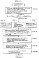
- Fig. 11 is a flowchart illustrating a typical sequence of the double-sided recording operation in a third embodiment of the present invention.
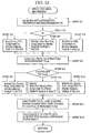
- Fig. 12 is a flowchart illustrating a typical sequence of the double-sided recording operation in a fourth embodiment of the present invention.
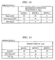
- Fig. 13 illustrates a typical smear table applied to the third embodiment of the present invention
- Fig. 14 illustrates a typical smear table applied to the fourth embodiment of the present invention.
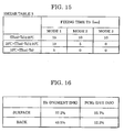
- Fig. 15 illustrates a typical smear table applied to the fourth embodiment of the present invention.
- Fig. 16 illustrates the ink discharge ratio of Bk ink to PCBk ink applied upon application of the double-sided recording operation in the fifth embodiment of the present invention
- Fig. 17 is a flowchart illustrating the sequence of the double-sided recording operation in a variation of the second embodiment of the invention.
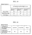
- Fig. 18 illustrates a typical smear table applied to a variation of the second embodiment of the present invention.
- Fig. 19 illustrates a typical table applied to the first embodiment of the present invention.
- FIG. 1 is a perspective view illustrating the whole configuration view of the ink-jet recording apparatus in an embodiment of the present invention
- Fig. 2 is a side sectional view of the ink-jet recording apparatus 1
- FIG. 3 is a schematic view of a recording medium reversing section 9 including a reversing unit 90.
- the paper feed section (II) the paper conveying section, (III) the carriage section, (IV) the cleaning section, (V) the paper feed section, and (VI) the recording medium reversing section will now be described with reference to Figs. 1 to 3 .
- the paper feed section 2 has a configuration in which a pressure plate 21 loading a reversing medium and a feed rotor 22 feeding a recording medium P are attached to a base 20.
- a movable side guide 23 is movably attached to the pressure plate 21. This movable side guide regulates the mounting position of the recording medium P.
- the pressure plate 21 is rotatable around a rotation shaft 21a connected to the base 20, and is energized by a pressure plate spring 24 toward a feed rotor 22.
- a separation pad 25 comprising a material having a high frictional coefficient such as an artificial leather is provided on the portion of the pressure plate 21 opposite to the feed rotor 22.
- the release cam 29 pushes the pressure plate 21 down to a prescribed position during standby state.
- the contact of the recording medium P and the feed rotor 22 mounted on the pressure plate 21 is in a released state.
- the driving force of the conveyance roller 36 is transmitted by gears or the like to the feed rotor 22 and the release cam 29, which leaves the pressure plate 21, the pressure plate 21 moves up; the feed rotor 22 and the recording medium P come into contact with each other; the recording medium P is picked up along with the rotation of the feed rotor 22 and begins being fed; and the recording medium P is separated sheet by sheet by the separation claw 26 and fed to the paper feed section.
- the feed rotor 22 and the release cam 29 rotate until the recording medium P is fed to the paper feed section 3, and at the point in time when feeding to the paper feed section 3 is completed, the contact of the recording medium P with the feed rotor 22 is released again into the standby state, and the driving force from the conveyance roller 36 is shut off.
- the paper feed section 3 has a conveyance roller 36 which conveys the recording medium P and a PE sensor 32.
- a pinch roller 37 which rotates following the rotation of the conveyance roller 36 is provided on the conveyance roller 36.
- the pinch roller 37 is rotatably supported by a pinch roller guide 30, and by energizing the pinch roller guide 30 with a pinch roller spring 31, the pinch roller 37 is caused to come into pressure-contact with the conveyance roller 36, thereby producing a conveyance force of the recording medium P.
- an upper guide 33 which guides the recording medium P and a platen 34 are arranged at the entry of the paper feed section 3.
- a PE sensor lever 35 which transmits detection of the leading end and the trailing end of the recording medium P to the paper end sensor (PE sensor) 32 is provided on the upper guide 33.
- the recording medium P sent to the paper feed section 3 and guided by the platen 34, the pinch roller guide 30 and the upper guide 33, is further sent to the roller pair of the conveyance roller 36 and the pinch roller 37.
- the PE sensor lever 35 rotates by being pushed by the leading end of the recording medium P, and the PE sensor 32 detects this rotation.
- the controller described later determines the recording position of the recording medium P on the basis of a detection signal of this PE sensor 32.
- the recording medium P is conveyed on the platen 34 by rotation of the roller pair 36 and 37 under the effect of a conveyance motor (not shown).
- the recording head 7 replaceably attached to a carriage 50 described later, and has a configuration in which it releasably holds an ink tank.
- a plurality of nozzles are arranged on this recording head 7, and thermo-electric conversion elements such as heaters are arranged in the individual nozzles. By dividing these thermo-electric conversion elements, heat is imparted to the ink, and causes the ink to produce membrane boiling. A change in pressure caused by growth or contraction of bubbles at this moment causes discharge of the ink from the nozzles to form an image on the recording medium P.
- the carriage section 5 has a carriage 50 to which the recording head 7 is replaceably mounted.
- the carriage 50 is supported movably in the main scanning direction by a guide shaft 81 extending in the main scanning direction perpendicular to the conveying direction of the recording medium P (sub-scanning direction) and a guide rail 82 which maintains the gap between the recording head 7 and the recording medium P.
- These guide shaft 81 and the guide rail 82 are attached to a chassis 8.
- the carriage 50 is driven via a timing belt 83 by a carriage motor (not shown) attached to the chassis.
- the timing belt 83 is supported by an appropriate tension between idle pulleys 84.
- a flexible substrate 56 for transmitting a head driving signal from an electric substrate 9 to the recording head 7 is connected to the carriage 50.
- the recording medium P when an image is formed on the recording medium P, the recording medium P is conveyed by the rotation of the roller pair 36 and 37 in the sub-scanning direction, and the recording medium P is caused to move to the recording position on the platen 34.
- the carriage 50 is driven by the carriage motor 80, and the recording head 7 is moved to the image forming position on the recording medium P in the main scanning direction. Subsequently, the carriage 50 moves toward the main scanning direction in accordance with a recording start instruction, and the image is formed by discharging the ink from the recording head 7 toward the recording medium P in response to a signal from the electric substrate 9.
- Attachment and detachment of the recording head 7 to and from the carriage 50, and attachment and detachment of the ink tank to and from the recording head 7 are accomplished by causing the carriage 50 to a prescribed replacement position by pressing an operating key (not shown) and replacing the component at this replacement position.
- the cleaning section 6 comprises a pump 60 which performs cleaning of the recording head 7, a cap 61 for inhibiting drying of the recording head 7, and a drive switching arm 62 which switches over the rotating driving force of the conveyance roller 36 to the paper feed section 2 and the pump 60.
- the driving force is not transmitted to the paper feed section 2 or the pump 60 because the drive switching arm 62 fixes a planetary gear (not shown) rotating around the axial center of the conveyance roller 36 at a prescribed position.
- the drive switching arm 62 is moved in the arrow A direction under the effect of movement of the carriage 50, the planetary gear becomes free.
- the planetary gear (not shown) therefore moves in response to positive or negative rotation of the conveyance roller 36: the positive rotation of the conveyance roller 36 causes the driving force to be transmitted to the paper feed section 2, and the negative rotation causes the driving force to be transmitted to the pump 60.
- Two paper discharge rollers 41 and 41A are arranged at positions of different sub-scanning directions in the paper discharge section 4 which comprises a transmission roller 40 in contact with the conveyance roller 36 and the paper discharge roller 41, and the transmission roller 40 in contact with the paper discharge roller 41 and the paper discharge roller 41A. Therefore, the rotating driving force of the conveyance roller 36 is transmitted to the paper discharge roller 41 via the transmission roller 40, and this rotating driving force is further transmitted to the paper discharge roller 41A via the transmission roller 40A.
- Spurs 42 and 42A are in contact with the paper discharge rollers 41 and 41A, respectively, so as to be rotatable following the rotation of the paper discharge rollers 41 and 41A, and a cleaning roller 44 is rotatably in contact with the spurs 41 and 41A.
- the recording medium P on which the image has been formed in the carriage section 5 is held between the above-mentioned paper discharge roller 41 and 41A and the spurs 42 and 42A, is conveyed by the rotation of these rollers, and is discharged onto a paper discharge tray 100.
- a paper discharge support 104 for supporting the recording medium P discharged after recording is provided in the downstream of the paper discharge roller 41A.
- the paper discharge support 104 is attached rotatably to a guide member 102.
- the guide member 102 is supported linearly movably between a projecting position from the platen 34 and a retracted position onto the platen 34.
- the paper discharge support 104 performs rotating operation along with the movement of this guide member 102.
- the conveyance path of the recording medium from the above-mentioned paper feed section 2 through the recording head 7 to the paper discharge support 104 forms a first conveyance path.
- the recording medium reversing section 9 comprises a paper feed conveyance path 94 following the above-mentioned first conveyance path, the conveyance roller 36 and a reversing unit 90 positioned on the back (to the right in Fig. 2 ) of the ink-jet recording apparatus 1.
- the reversing unit 90 is composed of a paper holding roller 95, a reversing small roller 92, a loop-shaped reversing conveyance path 93, and a reversing large roller 91.
- the conveyance roller 36 can be rotation-driven by a motor in the positive and the negative directions.
- the above-mentioned paper feeding conveyance path 94 and the above-mentioned reversing conveyance path 93 form a second conveyance path.
- the reversing unit 90 is attachable to the recording apparatus.
- the conveyance roller 36 is driven in a reverse direction to send the recording medium P in the paper feed conveyance path 94 to the reversing conveyance path 93, where the surface/back of the recording medium P is reversed. More specifically, the recording medium P passes through the reversing conveyance path 93 in a sequence of A ⁇ B ⁇ C ⁇ D ⁇ E ⁇ F ⁇ G, as shown in Fig. 3 , thus reversing the surface/back surface.
- the recording medium P of which the surface and the back have been reversed is sent through the paper feed conveyance path 94 again to the platen 34 so that the other surface (referred to as the "back” or the “second recording surface”) is subjected to recording only the recording head 7.
- reference numeral 100 represents a control section which performs control of individual driving sections of the ink-jet recording apparatus of this embodiment, and has an MPU 101 performing processes such as various operations, determination and control; a ROM 102 storing programs and the like for execution by this MPU 101; a DRAM 103 which temporarily stores the entered data and functions as a work area for arithmetic operations by the MPU 101; and a gate array (G.A.) 104.
- An interface 105 for exchanging signals with external devices such as a host computer (not shown) is connected to the control section 100.
- a head driver 108 which drives heaters provided in the individual nozzles of the recording head 7, a motor driver 110 which drives a conveyance motor 109 rotationally driving the conveyance roller 36 and the like, and a motor driver 112 which drives a carriage motor 111 driving the carriage 50 are connected to this controller 100.
- An encoder 111 which detects the position of the carriage 50 and the above-mentioned PE sensor 113 are connected to the controller 100.
- the data to be recorded when data to be recorded is sent from the host computer via the interface 105, the data is temporarily stored via the gate array 104 into the DRAM 103. Thereafter, the data in the DRAM 103 is converted by the gate array 104 from raster data into recording image data for recording with the recording head 7, and is stored again in the DRAM 103. The data is sent again by the gate array 104 via the head driver 108 to the recording head 7. The heater at the corresponding nozzle position is driven to generate heat, and the ink is discharged by the resulting heat energy for recording. The counter of dots to be recorded is held on the gate array 104 to permit counting of the number of recorded dots at a high rate.
- the carriage motor 111 is activated via the motor driver 112 of the carriage motor 111, and the recording head 7 is moved in the main scanning direction, together with the carriage 50, in match with the dot forming rate of the recording head 7.
- interruption control is applied to the gate array 104 from the MPU 100 every 10 msec, and the amount of integration of counter values of the number of counted dots is read out. This permits acquisition of information about the number of dots to be recorded in unit region during a unit period of time. It is also possible to calculate a recording duty per unit region on the basis of this number of recorded dots per unit region.
- the number of recorded dots per unit region as herein used means a number of actually recorded dots for each of a plurality of unit regions (dot count regions W) obtained by dividing the regions on the recording medium into a plurality of portions.
- the recording duty in a recording head having a nozzle train width of 160 nozzles, the number of recorded dots during 10 msec (corresponding to 100-dot width in the main scanning direction when driving the recording head at 10 kHz) is counted.
- the recording duty for a unit region can be calculated on the basis of the resultant count value and the time (10 msec).
- a recording duty of 100% is defined, and the recording duty is thus calculated for each unit region.
- Each of the plurality of divided regions resulting from division of the regions on the recording medium into a plurality of portions is defined as a dot count region W.
- the size of the dot count region W should preferably be relatively small. The reason thereof will be described with reference to Figs. 6A and 6B .
- Fig. 6A illustrates a state in which a solid printing region R recorded at a recording duty of 100% completely overlaps a dot count region W (for convenience of showing these regions R and W, the recording region R and the dot count region W are shown at positions slightly apart from each other). In this case, all the dots recorded in the recording region are counted, leading to a detection result of a recording duty of 100%.
- the recording position deviates by 80 nozzles in the sub-scanning direction (up/down direction in Fig. 6B ), relative to the position where recording should originally be made.
- Fig. 6B illustrates a case where further the read timing of data to be recorded shifts in the main scanning direction by 5 msec.
- the detection result detected by the count region W in Fig. 6B is equal to a recording duty of 25%, thus producing a detection error.
- a detection error is difficult to find if the size of the recording region R is wider in the longitudinal as well as transverse directions than the dot count region W, leading to an improved detection accuracy. It is therefore very effective to reduce the size of the dot count region W by accomplishing counting by dividing the region in the nozzle train direction, or by reducing the interruption interval. If the dot count region W is smaller in size, the read error occurs for a very small solid region having a fair fixability. The possibility of causing problems is low in preventing occurrence of smears.
- the size of the dot count region W should therefore preferably be determined comprehensively and appropriately taking into account the above-mentioned circumstances.
- the technique of accumulating results of detection of a plurality of neighboring dot count regions W and determining the extent of recording duty of these plurality of regions on the basis of the extent of this cumulative value is suitably applicable.
- Pieces of information about the quantity of ink to be imparted to the unit region include, for example, the number of dots recorded in a unit region, and the recording duty in a unit region.
- Information indirectly relating to the quantity of imparted ink can be suitably used as described above. It is needless to mention that not only such indirect information, but also information expressed by converting this indirect information into a quantity of imparted ink, i.e., information directly showing the quantity of imparted ink may be applied.
- information about the number of recorded dots, information about recording duty, or information directly showing the quantity of imparted ink is applicable as information relating to the quantity of ink to be imparted to a unit region (for example, a dot count region W described later).
- all pieces of information relating directly or indirectly to the quantity of imparted ink per unit region are included in the above-mentioned information relating to the quantity of ink to be imparted to the unit region.
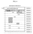
- the divided regions obtained by dividing the region corresponding to one of the surfaces of the recording medium, as shown in Fig. 8 , in the main scanning direction (right-left direction in Fig. 8 ) as well as in the sub-scanning direction (up-down direction in Fig. 8 ) into a plurality of portions are defined as unit regions to be covered by dot counting (dot count region W).
- dot counting dot count region W
- the size of the unit region (dot count region W) should preferably be the smallest possible. It is therefore a feature of the present invention to divide the region both in the main scanning direction and in the sub-scanning direction.
- the drying time is not determined in response to the number of recorded dots for the entire area of one of the surfaces of the recording medium as in the above-mentioned US Patent No. 6,149, 327 specification, but the drying time is determined according to the number of recorded dots for each unit region as described above. Therefore, even when small regions having a large number of recorded dots (a high recording duty) locally exist, a relatively long drying time is set, thereby permitting reliable inhibition of the occurrence of smears.
- the end of operation relating to recording on one of the surfaces of the recording medium means a point in time when, for example, the last run of scanning is completed and the recording operation is discontinued, or in summary, when the recording medium reaches the standby position and the recording operation is in the stopped state.
- the start of operation relating to recording on the other surface means a point in time when the above-mentioned recording operation stopping state is cancelled, and the operation is resumed (for example, the conveyance operation necessary for recording on the other surface, or the conveyance operation for reversing the recording medium).
- the standby position of the recording medium in the recording operation stopping state a position near the position where the recording medium is introduced into the reversing unit 90 is appropriate.
- (1) the position where the last scanning run has been completed; or (2) the position where, after the completion of the last scanning run, the recording medium has been conveyed in the positive direction by a predetermined amount; or (3) the position where, after the completion of the last scanning run, the recording medium has been conveyed in the negative direction by a predetermined amount is suitable.
- the time until the ink drying (ink fixing) in the individual unit regions on the surface subjected to recording has almost been completed is set as the above-mentioned operation downtime (drying time).
- the conveyance operation of the recording medium necessary for recording on the other surface is not started.
- the conveyance operation of the recording medium is started.
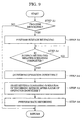
- step A1 it is determined, in step A1, which of the recording modes is specified from among the single-sided recording mode in which recording is performed only on one of the surfaces of the recording medium, and the double-sided recording mode in which the two surfaces including one of the surfaces of the recording medium and the other side.
- Specification of a recording mode may be accomplished by means of a mode specifying switch provided in the recording apparatus, or by means of a printer driver on the host computer connected to the recording apparatus.
- step A1 If the double-sided recording mode is not specified in step A1, the ordinary single-sided recording is performed, and this sequence is completed. If the two-side recording mode is specified, on the other hand, the process advances to step A2, in which recording is conducted on one of the surfaces of the recording medium. Thereafter, the process goes to step A3, in which it is determined whether or not the operation relating to recording on the surface has been completed.
- the end of the operation relating to the recording on the surface means a point in time when the last scanning run comes to an end and the recording operation is discontinued, i.e., the moment when the recording medium reaches the standby position.
- step A4 the time from the end of operation relating to recording on the surface until the start of operation relating to recording on the back (operation downtime T) is determined.
- the time required for perfectly fixing the ink in the individual unit regions of the surface subjected first to recording is set as the operation downtime T.
- this operation downtime T is determined on the basis of the information relation to the quantity of applied ink for each unit region determined as described above. Particularly in this example, a threshold value for determining whether or not to set an operation downtime T is set in advance. When there is a unit region in which the quantity of applied ink (number of recorded dots in this case) exceeds this threshold value, an operation downtime T is set. In other words, if there exists even a single unit region showing a quantity of imparted ink (number of recorded dots) exceeding a predetermined quantity (a predetermined number in this case) among the plurality of unit regions composing the surface of the recording medium, a prescribed operation downtime is set.
- this example is based on a process comprising the steps of counting the number of dots to be recorded in each of unit regions (dot count regions) resulting from division of the region corresponding to the surface of the recording medium as shown in Fig. 8 ; comparing the count value with the above-mentioned threshold value; and, when the count value exceeds the threshold value, setting a predetermined operation downtime T, or when the count value does not exceed the threshold value, setting an operation downtime T of 0.
- step A5 the lapse of this operation downtime T is waited for in step A5.
- an operation relating to recording on the back i.e., conveying operation along the above-mentioned second conveyance path for reversing the recording medium P by means of the reversing unit 90 is not carried out. Even when data to be recorded is received, the conveyance operation for recording on the back is not started. Then, after the lapse of the operation downtime T, the operation relating to recording on the back, i.e., the conveyance operation along the second conveyance path for reversing the recording medium P by means of the reversing unit 90 is started.
- the recording medium P is reversed in the reversing unit 90.
- recording on the back is conducted by discharging the ink from the recording head onto the other surface (back) of the recording medium on which recording has not as yet been conducted, in step A6.
- a sequence in this embodiment is now completed.
- a certain operation downtime T is set in the above-mentioned embodiment. More strictly, however, there should be a time required for ink drying (or fixing) in proportion to the extent of the quantity of applied ink per unit area. In order to minimize the necessary ink drying time, therefore, it is desirable to set the length of the operation downtime T variable in response to the extent of the quantity of applied ink. That is, it is desirable to set a much longer operation downtime if the quantity of applied ink is larger, and a much shorter operation downtime T if the quantity of applied ink is smaller.
- the unit region having the largest number of recorded dots is considered to require the longest time period for ink drying (fixing).
- the operation downtime T should therefore preferably be determined on the basis of the number of recorded dots in the unit region corresponding to the largest number of recorded dots, from among the plurality of unit regions. In this variation 1, therefore, the number of recorded dots is counted for each of the plurality of unit regions (dot count regions), and the largest number X of recorded dots is required therefrom.
- the operation downtime T is determined with reference to a table (smear table shown in Fig. 19 ) in which the number X of recorded dots and the operation downtime T are correlated in advance.
- the operation downtimes T are classified into three stages (TA, TB and TC) in accordance with the largest number X of recorded dots.
- the three stages represent preferable examples, and setting of two stages or four or more stages is also acceptable.
- a certain operation downtime T has been provided between the operation relating to recording on the surface and the operation relating to recording on the back in the example shown above. It is possible that operation downtime T is determined by taking into consideration the kind of ink.
- the kinds of ink applicable in an ink-jet recording apparatus include penetrating kinds of ink (for example, dye ink) having a high fixability, and superposing kinds of ink (for example, pigment ink) having a low fixability. While dye ink has a high penetrating property into a recording medium P, pigment ink has a low penetrating property, leading to a low fixability.
- the operation downtime after the completion of recording on the surface may be shorter than the predetermined operation downtime T, or it is possible to eliminate the operation downtime T.
- ink having a low fixability such as pigment ink
- it is possible to ensure fixing of the ink on the recording medium P by providing, after the completion of the operation relating to recording on the surface, an operation downtime T as described above, or an operation downtime longer than this. In this way, an unnecessary downtime can be reduced by considering the fixability of the ink, thus permitting improvement of throughput, and production of smears can be reliably prevented, leading to an improved reliability and to a higher general-use property.
- the fixability of the recording medium P is higher in the order of recording medium C ⁇ recording medium B ⁇ recording medium A.
- the operation downtime may be corrected according thereto. For example, in the case of (font size) ⁇ 25, the time to be added to the operation downtime is 0 seconds; in the case of 25 ⁇ (font size) ⁇ 50, a time of three seconds should be added to the operation downtime; and in the case of 50 ⁇ (font size), a time of five seconds may be added to the operation downtime.
- the drying time is not determined according to the quantity of applied ink for the entire area of one of the surfaces of the recording medium, but the drying time is determined on the basis of information about the quantity of ink to be applied to each of the unit regions obtained by dividing the region corresponding to one of the surfaces of the recording medium.
- the second embodiment is characterized in that the time required for ink drying (drying time, operation downtime) is determined by taking into account not only information relating to the quantity of imparted ink for each unit region, but also information relating to the position of the unit region (positional information, recording time information).
- unit regions closer to the leading end of the recording medium are subjected to recording in an earlier stage. Drying of the ink is at an advanced state upon the completion of the operation relating to recording on the surface. For the unit regions closer to the trailing end of the recording medium, on the other hand, recording is conducted in a later stage, and drying of the ink goes slow even upon the completion of the operation relating to recording on the surface. The extent of drying of the ink varies with the position of the unit region on the recording medium. It is therefore desirable to determine the ink drying time taking into account also the position of the unit region.
- the region corresponding to the surface of the recording region corresponding to the surface of the recording medium is divided in the sub-scanning direction into a plurality of control regions (regions 1 to 12), and for each of these plurality of control regions, information about the largest number of recorded dots in the unit region and positional information of that unit region are acquired.
- the operation downtime is determined on the basis of the thus acquired largest number of recorded dots and positional information of that unit region.
- region Nos. are assigned as shown in Fig. 7 , and the length in the sub-scanning direction of various recording media P is detected in compliance therewith. That is, the regions on the recording medium P are divided every inch in the sub-scanning direction into control regions L each having a width of 1 inch. Simultaneously with the start of the paper feed operation, counting of each control region is started. The length in the sub-scanning direction if the recording medium P is detected by means of the count value. For example, the fact that the recording medium P1 shown in Fig.
- the recording medium P2 can be determined to have a maximum length of 17 inches.
- the amount of retained memory can be derived from the maximum length of the recording medium in the sub-scanning direction applicable to the recording apparatus.
- Fig. 8 illustrates a case where there is recorded an image in which recorded regions showing a high recording duty as in recording of a black solid portion and recorded regions of a low recording duty as in recording of a text are mixed.
- the double-sided recording operation when recording such a mixed image on the both sides of the recording medium will be described.
- the regions of a high recording duty i.e., the regions in which black solid portions are recorded are covered by smear inhibiting control, and the regions in which only the text is recorded are not covered by smear inhibiting control. More specifically, from among the plurality of control regions (regions 1 to 12), the regions 2, 6, 7 and 8 are covered by smear inhibiting control.
- the manner of reflection of a dot count value may differ with the positional relationship with the recorded data regions R, the dot count regions W, and the control region width (the width corresponding to the conveyance pitch of the recording medium conveyed intermittently in the sub-scanning direction). For example, even a single continuous image is covered by smear control in the regions 6 and 7, whereas, in the region 5, the image is not covered by smear inhibiting control because of a small maximum number of recorded dots of the dot count region in the control regions thereof.
- Whether or not a region is covered by smear inhibiting control is decided, depending upon whether or not the number of unit regions showing a number of recorded dots exceeding the predetermined number exist. That is, when there are unit regions showing a number of recorded dots exceeding a predetermined number (threshold value), the control region including these unit regions is covered by smear inhibiting control. When there is no unit region showing a number of recorded dots exceeding the predetermined number, on the other hand, this control region is not covered by smear inhibiting control. When a region is covered by smear inhibiting control, an operation downtime is provided. When a region is not covered by smear inhibiting control, no operation downtime is provided.
- Dot counting is performed for each of a plurality of unit regions (dot count regions W) for each control region, and the maximum dot count value is acquired therefrom. It is determined whether or not the maximum dot count value exceeds a predetermined threshold value by comparing the maximum dot count value with the predetermined threshold value. In other words, it is determined, for each of the above-mentioned control regions (regions 1 to 12), whether or not unit regions of a high recording duty to be covered by the smear inhibiting control are contained in the page (surface) to be first subjected to recording. For a control region containing a unit region of a high recording duty exceeding the prescribed threshold value, the maximum dot count value and the positions of the unit regions are stored.
- the maximum dot count value and the position of the unit region are stored for the regions 2, 6, 7 and 8.
- the position of the control region in the sub-scanning direction is set forth as the position of the unit region.
- the time required until the unit region showing the maximum dot count value stored as described above no further produces smears is determined on the basis of the position of the unit region and the dot count value thereof for each of these control regions. More specifically, a table correlating the position of the unit region and the dot count value with the time up to the elimination of the risk of occurrence of smears is provided in advance, and the time required until the region becomes free from the risk of an occurrence of smears is determined on the basis of the position of the unit region and the dot count value. Since ink fixing is at a higher degree for unit regions closer to the leading end of the recording medium, the above-mentioned table is prepared by taking into account this fact.
- the time required until the region becomes free from the risk of an occurrence of smears is determined.
- the maximum time is adopted as the above-mentioned operation downtime.
- the region conjectured to show the worst ink fixing state at the moment when the operation relating to recording on the surface is completed is determined on the basis of the position of the unit region and the dot count value thereof, and the time required for completely fixing the region of the worst fixing state is set forth as the above-mentioned operation downtime.
- the recording medium P is conveyed to the reversing/conveyance path 93.
- the recording medium is conveyed to a position where the recording medium becomes opposite to the recording head, and reversing is carried out by discharging the ink from the recording head to the back of the recording medium.
- the time required for elimination of the risk of smear occurrence of the unit region showing the maximum dot count value has determined only for the control regions containing the unit regions to be covered by smear inhibiting control.
- This embodiment is not however limited to this.
- the times required until elimination of the risk of smear occurrence on the unit region showing the maximum dot count value may be determined, and the longest time among these times may be adopted as the above-mentioned operation downtime.
- the positional information of unit regions has been stored.
- Information not of the position itself may be used so far as it is information corresponding to the position of a unit region.
- information of the time Ts recording the unit region may be stored.
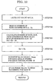
- step B1 recording data entered via the interface 105 is entered into the gate array (G.A.) as dot data which is then latched.
- the number of dots of an image to be recorded is counted by counting the number of dots of the thus latched dot data (binary value).
- step B2 the number of dots Dc counted by the gate array 104 is read in.
- step B3 the number of dots Dot recorded within a certain period of time is calculated by determining a difference between a dot count value Dc' read in the preceding run and a latest number of dots Dc.
- dot counting is carried out for 100 dots in the main scanning direction for every latching interval. Since 160 nozzles are arranged in the nozzle train direction on the recording head, the dot count region W subjected to dot counting for every latching interval has a size of 160 x 100 dots. The number of dots within this dot count region W is counted.
- step B4 the read new dot count value Dc is written over the dot count value Dc' read in the preceding run.
- step B5 maximum value Dmax among the numbers of dots Dot counted within the individual dot count regions W is stored for each counted region width L.
- the term the control region width L as herein used means a width corresponding to the amount of conveyance of the recording medium conducted intermittently in the sub-scanning direction, or a width in the sub-scanning direction (1 inch in Figs. 7 and 8 ) of the regions assigned numbers such as regions 1, 2, ..., N (N is a positive integer) in Figs. 7 and 8 .
- step B6 the times when recording is performed are stored for each control region width L.
- the time Ts is measured by the use of a timer built in the MPU 101.
- the maximum dot count value Dmax in the dot count region W and the time Ts of the unit region recording are stored for each control region width L.
- the maximum dot count values Dmax only values exceeding a threshold value predetermined as described above may be stored, or the values may be stored irrespective of whether or not the predetermined threshold value is exceeded.
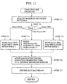
- the time required until the unit region showing the maximum dot count value becomes free from the risk of occurrence of smears is determined on the basis of the maximum dot count value Dmax and the time Ts of recording in the unit region.
- the longest time from among the times determined in correspondence to the individual control regions is set as the operation downtime.
- a maximum number of dots Dmax and a timer value Ts upon recording the unit region are acquired for each of a plurality of control regions forming the first recording surface of the recording medium.
- step E2 the maximum number of dots Dmax acquired in step E1 is compared with a plurality of threshold values (three threshold values TH1, TH2 and TH3 in this example) to determine the relative magnitude. If Dmax is larger than the threshold value TH2, the process advances to step C3, and if Dmax is larger than the threshold value TH1 and smaller than the threshold value TH2, the process goes to step E4. If Dmax is smaller than the threshold value TH1, then, the process advances to step E5. In steps E3, E4 and E5, a time T4 considered necessary for fixing is acquired in accordance with the smear table 4 shown in Fig. 18 .
- the smear table 4 shown here determines an operation downtime T4 by considering not only the number of dots Dmax, but also the fixability of the ink used. That is, in this smear table 4, recording modes 1, 2 and 3 are provided in the order of lower fixability of the ink used. According as ink of a lower fixability is used in a recording mode, the operation downtime T4 is longer, and according as the dot count value is larger, the operation downtime T4 is longer.
- the operation downtime is set at 0 so that a standby operation is not exceeded during the period of transfer from recording on the surface to recording on the back.
- pigment ink falls under the category of ink having a low fixability
- dye ink falls under the category of ink having a high fixability. Therefore, the above-mentioned mode 1 may be considered to be a mode in which only pigment ink is applicable; mode 2, pigment ink and dye ink are applicable; and mode 3, only dye ink is applicable.
- step E6 times required from the individual control regions up to the last control regions (Tlast - Ts) are calculated, respectively, from the timer values Ts upon recording in the individual control regions and the timer value Tlast upon recording in the last control region.
- the time T' required for fixing taking into account the time difference caused by the position of recording by subtracting the value resulting from the above calculation from the time T4 considered necessary for fixing.
- the time required for ink drying (drying time, operation downtime) is determined by taking into account not only the information about the quantity of applied ink for each unit region, but also the information about the position of the unit region (positional information, recording time information, etc.). It is therefore possible to set a drying time considering even a difference in the degree of ink drying according to the position on the recording medium. As a result, the occurrence of smears in the conveyance path including the reversing path can be inhibited while maintaining the throughput on a high level by setting a short drying time.
- the operation downtime is determined while considering not only the information about the quantity of imparted ink for each unit region, but also the information about fixability of the ink used.
- step C1 a maximum value is selected from among a plurality of maximum numbers of dots Dmax for individual control region width L on the surface of the recording medium through the control operation shown in Fig. 10 .
- a maximum recording duty Rmax is determined on the basis of the thus selected maximum value and stored.
- step C2 the maximum recording duty Rmax acquired in step C1 is compared to a plurality of threshold values (these threshold values (three threshold values TH1, TH2 and TH3 in this case) to determine the relative magnitude. If Rmax is larger than the threshold value TH2, the process advances to step C3, and if Rmax is larger than TH1 and smaller than the threshold value TH2, the process advances to step C4. If Rmax is smaller than the threshold value TH1, the process goes to step C5. In steps C3, C4 and C5, the time T1 considered necessary for fixing is acquired in accordance with the smear table 1 shown in Fig. 13 .
- a smear table based on conditions including a threshold value TH1 of 30% and a threshold value TH2 of 50% is shown in Fig. 13 .
- the smear table 1 determines the operation downtime T1 by taking into account not only the recording duty Rmax, but also the fixability of the ink used. That is, in this smear table 1, recording modes 1, 2 and 3 are provided in order of lower fixability of the ink used so that the operation downtime T1 is longer in a recording mode using ink of a lower fixability, and the operation downtime T1 is longer when the recording duty is higher. As shown in the recording mode 3, when the ink used has a high fixability and the recording duty is low, the operation downtime is set at 0 so that no standby operation is conducted during transfer from recording on the surface to recording on the back.
- the above-mentioned mode 1 may be considered to be a mode in which only pigment ink is applicable; mode 2, pigment ink and dye ink are applicable; and mode 3, only dye ink is applicable.
- the operation downtime T can be modified or set on the basis of the maximum recording duty on one of the surfaces of the recording medium and the fixability of the ink used for recording on this surface. It is therefore possible to inhibit the occurrence of smears in the conveyance path including the reversing path, and to efficiently perform recording operation, thus permitting maintenance of throughput on a high level.
- the fourth embodiment as in the above-mentioned second embodiment variation, it is possible to more reliably and more efficiently inhibit the occurrence of smears by determining the operation downtime T' during which the start of operation relating to recording on the back is discontinued on the basis of the maximum number of recorded dots on the surface, and connecting the above-mentioned recording operation downtime T' by taking into account the environmental temperature and the recording head temperature upon recording operation of the surface.
- the time required for ink fixing on the recording medium changes accordingly.
- the conveying operation and the reversing/conveying operation for recording on the back is started before perfect fixing of the ink, resulting in the risk of the occurrence of smears or secondary smears.
- a longer fixing time is provided to avoid an occurrence of smears caused by temperature.
- the apparatus has a configuration shown in Figs. 1 to 4 , further comprising a head temperature sensor which detects the recording head temperature and an environmental temperature sensor which detects temperature around the apparatus.
- the determining operation of the recording operation downtime to alleviate the effect of a change in the environmental temperature or the head temperature in the fourth embodiment will be described on the basis of the flowchart shown in Fig. 12 .
- step D1 after the completion of recording on the surface of the recording medium, the environmental temperature Te is acquired by means of an environmental temperature sensor provided on the base of the recording apparatus. Then in step D2, relative sizes of the value of the environmental temperature Te and predetermined threshold values TH3 and TH4 are determined. If the environmental temperature Te is larger than the threshold value TH2, the process advances to step D4. If the environmental temperature Te is smaller than the threshold value TH3 and larger than the threshold value TH4, the process goes to step D4. If the environmental temperature Te is smaller than the threshold value TH4, the process advances to step D5. In each of steps D3, D4 and D5, a correction time T2 during stoppage of operation is acquired in accordance with the smear table 2 shown in Fig. 14 .
- step D6 the head temperature Thed is acquired by means of the head temperature detecting sensor. Then in step D7, the difference in temperature between the head temperature Thed and the environmental temperature Te (Thed - Te) is determined. If this temperature difference (Thed - Te) is over the threshold value TH5, the process goes to step D8. If the temperature difference (Thed - Te) is smaller than the threshold value TH5 and larger than the threshold value TH6, the process advances to step D9. If the temperature difference (Thed - Te) is smaller than the threshold value TH6, the process goes to step D10. In each of steps D8, D9 and D10, a correction fixing time T3 corresponding to the recording head and the environmental temperature is acquired in accordance with the smear table 3 shown in Fig. 15 .
- step D11 the value of addition (T2 + T3) of the recording operation downtimes T2 and T3 acquired in steps D6 and D11 is determined, and the result is set as the correction time in response to the change in temperature.
- the smear table 2 shown in Fig. 14 represents a case based on conditions including a threshold value TH3 of 25°C and a threshold value TH4 of 15°C.
- the smear table 3 shown in Fig. 15 represents a case based on conditions including a threshold value TH5 of 20°C and a threshold value TH6 of 10°C.
- the recording modes 1, 2 and 3 shown in Figs. 14 and 15 represent values of fixability of ink: the recording modes 1, 2 and 3 are set in the order of lower ink fixability values, and a lower ink fixability corresponds to a longer correction time. In each of the modes, a higher temperature Te or a larger temperature difference (Thed - Te) leads to setting of a longer correction time.
- dispersion of the ink fixing time caused by a change in the environmental temperature or the head temperature can be taken into account, permitting achievement of a more reliable and more efficient recording operation, and it is possible to inhibit the occurrence of smears and secondary smears.
- an operation downtime during the period from recording on the surface up to transfer to recording on the back is set by considering the number of recorded dots, the recording duty, the environmental temperature, and the recording head temperature.
- the fixing time to the recording medium is reduced by mixing black ink using high-fixability dye ink (PCBk ink) such as C, M or Y with black pigment ink. This makes it possible to reduce the recording operation downtime and to perform more efficient recording operation.
- PCBk ink high-fixability dye ink
- the percentage of the dye-based PCBk ink is increased in the surface recording operation than in the recording operation on the back, and the percentage of the pigment-based Bk ink is decreased.
- the change in the ratio of the dye-based ink to the pigment-based ink may result in a difference in density, setting of the percentage must be conducted while considering this possibility.
- the percentage of the dye-based PCBk ink is reduced, and the percentage of the pigment-based Bk ink is increased.
- percentages as shown in Fig. 16 are set as a typical example of the mixing ratio of the dye-based ink to the pigment-based ink which permits reduction of the operation downtime.
- Bk ink For the Bk ink, a case of injection of 30 pl at a recording density of 600 dpi was assumed to have a percentage of 100%, and for the PCBk ink, a case of injection of 10 pl for each color at a recording density of 600 dpi was assumed to have a percentage of 100%.
- the surface recording was carried out with a Bk of 37.2% and a PCBk of 24.7%, and the back recording was conducted with a Bk of 43.5% and a PCBk of 12.2%.
- the PCBk ink and the Bk ink were mixed at the ratio as described above, and recording was applied on the surface and the back. As a result, the ink fixing time on the surface was reduced, making it possible to reduce the recording operation downtime. On the other hand, a difference in ink concentration between the surface and the back and occurrence of a back penetration were eliminated, thus permitting conducting a more reliable and more efficient double-sided recording.
- the apparatus may take the form of determining the density level of multi-value data prior to binarization, so far as the data correspond to the quantity of applied ink.
- the present invention may be applied to a system comprising a plurality of devices (for example, a host computer, an interface device, a reader, a printer, etc.) or to an apparatus comprising a single device (for example, a copying machine, a facsimile machine).
- a system comprising a plurality of devices (for example, a host computer, an interface device, a reader, a printer, etc.) or to an apparatus comprising a single device (for example, a copying machine, a facsimile machine).
- the present invention is also applicable to a case where an apparatus or a computer in a system are connected to various devices to operate them so as to achieve functions of the above-mentioned embodiments; software program codes for achieving such functions of the embodiments are supplied to such an apparatus or computer to operate these various devices in accordance with the programs thus supplied and mounted to and on the system or the computer (CPU or MPU).
- the software program codes themselves serve to achieve the functions of the embodiments, and the program codes themselves, and means for supplying such program codes to the computer, such as a storage medium storing these program codes are within the scope of the present invention.
- Storage media storing such program codes include a Floppy (registered trademark) disk, a hard disk, an optical disk, a magneto-optical disk, a CD-ROM, a magnetic tape, a non-volatile memory card, and a ROM.
- the present invention is not limited by the number of recording heads or the kind thereof, but is applicable to ink-jet recording apparatuses mounting various numbers of heads and any of various kinds of recording head. That is, the applicable recording modes include not only the recording mode using only a main color of black, but also recording modes such as a multi-color of different colors or full color mode based on mixture of colors. The present invention is applicable to ink-jet recording apparatuses capable of executing these recording modes.
Landscapes
- Ink Jet (AREA)
- Accessory Devices And Overall Control Thereof (AREA)
Claims (13)
- Tintenstrahlaufzeichnungsvorrichtung (1), die eine Aufzeichnung auf einer Oberfläche eines Aufzeichnungsmediums (P) und dessen anderer Oberfläche ermöglicht, indem ein Aufzeichnungskopf (7) zum Austragen von Tinte veranlasst wird, in Bezug auf das Aufzeichnungsmedium (P) in einer ersten Richtung eine Abtastung durchzuführen, umfassend:eine Erfassungseinrichtung, die Information über die Menge Tinte erfasst, die auf einzelne Einheitszonen (W) aufzubringen ist, welche man erhält durch Unterteilen einer Zone des Aufzeichnungsmediums (P) in der ersten Richtung und einer zweiten, zur ersten Richtung rechtwinkligen Richtung; undeine Bestimmungseinrichtung, welche die Zeitdauer vom Ende des Betriebs bezüglich der Aufzeichnung auf einer der Oberflächen des Aufzeichnungsmediums (P) bis zum Start des Betriebs bezüglich der Aufzeichnung auf der anderen Oberfläche des Aufzeichnungsmediums (P) bestimmt;wobei die Bestimmungseinrichtung die Zeitdauer auf der Grundlage von von der Erfassungseinrichtung erfassten Information bestimmt, welche die maximale Menge Tinte wiedergibt, die entsprechend den einzelnen Einheitszonen (W) aufzubringen ist.
- Tintenstrahlaufzeichnungsvorrichtung (1) nach Anspruch 1 , wobei das Ende von Betriebsabläufen bezüglich der Aufzeichnung auf einer der Oberflächen des Aufzeichnungsmediums (P) ein Zeitpunkt ist, zu dem die letzte Abtastung der einen der Oberflächen durch den Abtastkopf (7) abgeschlossen ist.
- Tintenstrahlaufizeichnungsvorrichtung (1) nach Anspruch 1, wobei das Ende der Betriebsabläufe bezüglich der Aufzeichnung auf einer der Oberflächen des Aufzeichnungsmediums (P) ein Zeitpunkt ist, zu dem das Aufzeichnungsmedium (P), auf der die Aufzeichnung vorgenommen wurde, eine Standby-Position erreicht.
- Tintenstrahlaufzeichnungsvorrichtung (1) nach Anspruch 3, wobei die Standby-Position eine Position ist, an der nach Abschluss der letzten Abtastung einer der Oberflächen das Aufzeichnungsmedium (P) über eine vorbestimmte Strecke transportiert wurde.
- Tintenstrahlaufzeichnungsvorrichtung (1) nach einem der Ansprüche 1 bis 4, wobei die Erfassungseinrichtung die Information über die Menge Tinte erfasst durch Zählen der Anzahl binärer Daten entsprechend den einzelnen Einheitszonen (W).
- Tintenstrahlaufizeichnungsvorrichtung (1) nach einem der Ansprüche 1 bis 4, wobei die Erfassungseinrichtung die Information über die Menge Tinte auf der Grundlage des Dichteniveaus mehrwertiger Daten entsprechend den einzelnen Einheitszonen (W) erfasst.
- Tintenstrahlaufizeichnungsvorrichtung (1) nach einem der Ansprüche 1 bis 6, wobei die Bestimmungseinrichtung eine erste Zeitdauer bestimmt, wenn Information über die maximale Menge aufzubringende Tinte, die von der Erfassungseinrichtung erfasst wird, die Information ist, die eine erste Menge aufzubringende Tinte wiedergibt, und eine zweite Zeitdauer, die länger als die erste Zeitdauer ist, bestimmt, wenn die erfasste Information über die maximale Menge aufzubringender Tinte, die Information ist, welche eine zweite Menge aufzubringender Tinte wiedergibt, die größer ist als die erste Menge aufzubringender Tinte.
- Tintenstrahlaufzeichnungsvorrichtung (1) nach einem der Ansprüche 1 bis 6, wobei die Bestimmungseinrichtung die Zeitdauer auf der Grundlage der Information über die maximale Menge aufzubringender Tinte und der Information über eine Position in der zweiten Richtung einer Einheitszone (W), welche die maximale Menge aufzubringender Tinte wiedergibt, bestimmt.
- Tintenstrahlaufzeichnungsvorrichtung (1) nach einem der Ansprüche 1 bis 8, wobei der Start der Betriebsabläufe bezüglich der Aufzeichnung auf der anderen Oberfläche des Aufzeichnungsmediums (P) ein Zeitpunkt ist, zu dem ein Transportvorgang gestartet wird, der notwendig ist für die Aufzeichnung auf der anderen Oberfläche.
- Tintenstrahlaufzeichnungsvorrichtung (1) nach einem der Ansprüche 1 bis 9, weiterhin umfassend:einen ersten Transportweg zum Transportieren des Aufzeichnungsmediums; undeinen zweiten Transportweg zum Transportieren des Aufzeichnungsmediums (P), wobei der zweite Transportweg sich zumindest teilweise vom ersten Transportweg unterscheidet, wobei nach Ausführung der Aufzeichnung auf einer der Oberflächen des Aufzeichnungsmediums (P), das entlang dem ersten Transportweg transportiert wird, das Aufzeichnungsmedium entlang dem zweiten Transportweg transportiert wird und anschließend eine Aufzeichnung auf der anderen Oberfläche des Aufzeichnungsmediums (P) ausgeführt wird.
- Tintenstrahlaufzeichnungsvorrichtung (1) nach Anspruch 10, wobei der zweite Transportweg einen Umkehrweg enthält, durch den das Aufzeichnungsmedium (P) nach der Aufzeichnung auf der einen Oberfläche umgekehrt wird.
- Tintenstrahlaufzeichnungsvorrichtung (1) nach einem der Ansprüche 1 bis 6,
wobei die Zeitdauer geändert wird auf der Grundlage der Information über die maximale Menge aufzubringender Tinte und mindestens einer von der Information über die Art der Tinte, der Information über die Art des Aufzeichnungsmediums (P), der Information über die Schriftzeichengröße, der Information über die Umgebungstemperatur im Bereich des Aufzeichnungskopfs (7), und der Information über die Temperatur des Aufzeichnungskopfs (7). - Verfahren zum Steuern einer Tintenstrahlaufzeichnungsvorrichtung (1), die einen zum Austragen von Tinte dienenden Aufzeichnungskopf (7) veranlasst, eine Abtastung in Bezug auf ein Aufzeichnungsmediums (P) in einer ersten Richtung durchzuführen, um dadurch eine Aufzeichnung auf einer Oberfläche und der anderen Oberfläche des Aufzeichnungsmediums (P) zu ermöglichen, umfassend:einen Erfassungsschritt zum Erfassen von Information über die Menge Tinte, die auf einzelne Einheitszonen (W) aufzubringen ist, welche man erhält durch Unterteilen der Zone entsprechend der einen Oberfläche des Aufzeichnungsmediums (P) in die erste Richtung und eine zweite, zur ersten Richtung rechtwinklige Richtung, für jede Einheitszone (W); undeinen Bestimmungsschritt zum Bestimmen der Zeitdauer vom Ende des Betriebs bezüglich der Aufzeichnung auf einer der Oberflächen des Aufzeichnungsmediums (P) bis zum Start des Betriebs bezüglich der Aufzeichnung auf der anderen Oberfläche des Aufzeichnungsmediums (P);wobei im Bestimmungsschritt die Zeitdauer bestimmt wird auf der Grundlage der Information über die maximale Menge aufzubringender Tinte aus den im Erfassungsschritt erfassten Informationsstücken bezüglich der Menge aufzubringender Tinte für die einzelnen Einheitszonen (W).
Applications Claiming Priority (2)
| Application Number | Priority Date | Filing Date | Title |
|---|---|---|---|
| JP2003343689 | 2003-10-01 | ||
| JP2003343689 | 2003-10-01 |
Publications (2)
| Publication Number | Publication Date |
|---|---|
| EP1520717A1 EP1520717A1 (de) | 2005-04-06 |
| EP1520717B1 true EP1520717B1 (de) | 2012-03-07 |
Family
ID=34309121
Family Applications (1)
| Application Number | Title | Priority Date | Filing Date |
|---|---|---|---|
| EP04255966A Expired - Lifetime EP1520717B1 (de) | 2003-10-01 | 2004-09-29 | Tintenstrahlaufzeichnungsgerät und Regelungsverfahren eines vorgenannten Gerätes |
Country Status (3)
| Country | Link |
|---|---|
| US (2) | US7204572B2 (de) |
| EP (1) | EP1520717B1 (de) |
| CN (1) | CN100348422C (de) |
Families Citing this family (13)
| Publication number | Priority date | Publication date | Assignee | Title |
|---|---|---|---|---|
| JP4164418B2 (ja) * | 2003-07-17 | 2008-10-15 | キヤノン株式会社 | 記録装置、記録方法、およびプログラム |
| EP1520717B1 (de) * | 2003-10-01 | 2012-03-07 | Canon Kabushiki Kaisha | Tintenstrahlaufzeichnungsgerät und Regelungsverfahren eines vorgenannten Gerätes |
| US7708361B2 (en) * | 2006-09-22 | 2010-05-04 | Fujifilm Corporation | Inkjet recording apparatus and inkjet recording method |
| JP5360342B2 (ja) * | 2007-05-31 | 2013-12-04 | ブラザー工業株式会社 | 両面記録装置 |
| US8070249B2 (en) * | 2007-08-20 | 2011-12-06 | Canon Kabushiki Kaisha | Inkjet printing apparatus and inkjet printing method |
| JP5198116B2 (ja) * | 2008-03-28 | 2013-05-15 | 富士フイルム株式会社 | インクジェットプリンタ、およびインクジェット記録方法 |
| JP5311980B2 (ja) * | 2008-11-20 | 2013-10-09 | キヤノン株式会社 | インクジェット記録装置 |
| JP2011051202A (ja) * | 2009-09-01 | 2011-03-17 | Canon Inc | インクジェット記録装置及びインクジェット記録方法 |
| JP5791375B2 (ja) * | 2011-05-26 | 2015-10-07 | キヤノン株式会社 | 記録装置および記録方法 |
| JP6548416B2 (ja) | 2014-03-27 | 2019-07-24 | キヤノン株式会社 | 記録装置、記録装置の制御方法、およびプログラム |
| JP2017064964A (ja) * | 2015-09-29 | 2017-04-06 | ブラザー工業株式会社 | 記録装置 |
| JP6558182B2 (ja) * | 2015-09-29 | 2019-08-14 | ブラザー工業株式会社 | 記録装置 |
| JP7452182B2 (ja) * | 2020-03-30 | 2024-03-19 | セイコーエプソン株式会社 | プリンターおよびプリンターの制御方法 |
Family Cites Families (7)
| Publication number | Priority date | Publication date | Assignee | Title |
|---|---|---|---|---|
| US6149327A (en) * | 1999-12-22 | 2000-11-21 | Hewlett-Packard Company | Method and apparatus for determining and controlling inkjet printing drying time |
| US6652060B2 (en) * | 2000-07-12 | 2003-11-25 | Canon Kabushiki Kaisha | Image recording apparatus, image recording method, storage medium which stores computer-readable program and the same program |
| JP3774640B2 (ja) * | 2001-05-17 | 2006-05-17 | キヤノン株式会社 | インクジェット記録装置及びインクジェット記録方法 |
| CN2532979Y (zh) * | 2002-04-09 | 2003-01-29 | 旭丽股份有限公司 | 双面打印装置 |
| JP2003343689A (ja) | 2002-05-31 | 2003-12-03 | Nsk Warner Kk | ステータ |
| US20040021741A1 (en) * | 2002-07-30 | 2004-02-05 | Ottenheimer Thomas H. | Slotted substrate and method of making |
| EP1520717B1 (de) * | 2003-10-01 | 2012-03-07 | Canon Kabushiki Kaisha | Tintenstrahlaufzeichnungsgerät und Regelungsverfahren eines vorgenannten Gerätes |
-
2004
- 2004-09-29 EP EP04255966A patent/EP1520717B1/de not_active Expired - Lifetime
- 2004-09-29 CN CNB2004100806584A patent/CN100348422C/zh not_active Expired - Fee Related
- 2004-09-29 US US10/953,946 patent/US7204572B2/en not_active Expired - Fee Related
-
2007
- 2007-03-08 US US11/683,925 patent/US7578570B2/en not_active Expired - Lifetime
Also Published As
| Publication number | Publication date |
|---|---|
| US7578570B2 (en) | 2009-08-25 |
| EP1520717A1 (de) | 2005-04-06 |
| US20070153041A1 (en) | 2007-07-05 |
| US7204572B2 (en) | 2007-04-17 |
| CN1603126A (zh) | 2005-04-06 |
| CN100348422C (zh) | 2007-11-14 |
| US20050073535A1 (en) | 2005-04-07 |
Similar Documents
| Publication | Publication Date | Title |
|---|---|---|
| US7578570B2 (en) | Ink-jet recording apparatus and control method of said apparatus | |
| KR100480855B1 (ko) | 잉크 제트 인쇄 장치 및 잉크 제트 인쇄 방법 | |
| JP2785031B2 (ja) | シリアルプリンタ | |
| JP4845429B2 (ja) | インクジェット記録装置 | |
| JP2004025557A (ja) | インクジェット記録装置、インクジェット記録方法、プログラムおよび記憶媒体 | |
| JP2005125517A (ja) | 印刷装置 | |
| US6969141B2 (en) | Ink jet recording apparatus and ink jet recording method | |
| US6991387B2 (en) | Printing apparatus and printing position adjustment method | |
| JP2005125750A (ja) | インクジェット記録装置および当該装置の制御方法 | |
| JP2004082348A (ja) | 記録装置 | |
| JP2004160797A (ja) | 記録装置 | |
| US6886900B2 (en) | Inkjet image forming apparatus and inkjet image forming method | |
| JPH06211398A (ja) | 印字装置 | |
| JP2010215399A (ja) | ベルト搬送装置、及びベルト搬送プログラム | |
| JP2002113851A (ja) | インクジェット記録装置及び該記録装置の回復処理制御方法 | |
| EP0862314B1 (de) | Aufzeichnungsgerät und Verfahren zur Steuerung eines solchen Aufzeichnungsgeräts | |
| JP2004216895A (ja) | インクジェットプリンタの白線補正装置及びその制御方法。 | |
| JP4571094B2 (ja) | 画像形成装置及びベルト搬送装置 | |
| JP2004167989A (ja) | インクジェット記録装置及びインクジェット記録方法 | |
| JP2007062249A (ja) | 画像形成装置 | |
| JP2006297869A (ja) | 記録装置および画像通信装置 | |
| JPH04368877A (ja) | 画像形成装置 | |
| US20040001216A1 (en) | Method for preventing repeat printing to a document | |
| JP3093625U (ja) | プリンタ、プリンタシステム、およびプリンタ制御装置 | |
| JP2006069163A (ja) | 画像形成装置 |
Legal Events
| Date | Code | Title | Description |
|---|---|---|---|
| PUAI | Public reference made under article 153(3) epc to a published international application that has entered the european phase |
Free format text: ORIGINAL CODE: 0009012 |
|
| AK | Designated contracting states |
Kind code of ref document: A1 Designated state(s): AT BE BG CH CY CZ DE DK EE ES FI FR GB GR HU IE IT LI LU MC NL PL PT RO SE SI SK TR |
|
| AX | Request for extension of the european patent |
Extension state: AL HR LT LV MK |
|
| 17P | Request for examination filed |
Effective date: 20050914 |
|
| AKX | Designation fees paid |
Designated state(s): DE FR GB IT |
|
| GRAP | Despatch of communication of intention to grant a patent |
Free format text: ORIGINAL CODE: EPIDOSNIGR1 |
|
| GRAS | Grant fee paid |
Free format text: ORIGINAL CODE: EPIDOSNIGR3 |
|
| GRAA | (expected) grant |
Free format text: ORIGINAL CODE: 0009210 |
|
| AK | Designated contracting states |
Kind code of ref document: B1 Designated state(s): DE FR GB IT |
|
| REG | Reference to a national code |
Ref country code: GB Ref legal event code: FG4D |
|
| REG | Reference to a national code |
Ref country code: DE Ref legal event code: R082 Ref document number: 602004036785 Country of ref document: DE Representative=s name: WESER & KOLLEGEN, DE Ref country code: DE Ref legal event code: R082 Ref document number: 602004036785 Country of ref document: DE Representative=s name: KILBURN & STRODE LLP, GB |
|
| REG | Reference to a national code |
Ref country code: DE Ref legal event code: R096 Ref document number: 602004036785 Country of ref document: DE Effective date: 20120503 |
|
| REG | Reference to a national code |
Ref country code: DE Ref legal event code: R082 Ref document number: 602004036785 Country of ref document: DE Representative=s name: WESER & KOLLEGEN, DE |
|
| PLBE | No opposition filed within time limit |
Free format text: ORIGINAL CODE: 0009261 |
|
| STAA | Information on the status of an ep patent application or granted ep patent |
Free format text: STATUS: NO OPPOSITION FILED WITHIN TIME LIMIT |
|
| 26N | No opposition filed |
Effective date: 20121210 |
|
| REG | Reference to a national code |
Ref country code: DE Ref legal event code: R097 Ref document number: 602004036785 Country of ref document: DE Effective date: 20121210 |
|
| PGFP | Annual fee paid to national office [announced via postgrant information from national office to epo] |
Ref country code: IT Payment date: 20140903 Year of fee payment: 11 |
|
| PGFP | Annual fee paid to national office [announced via postgrant information from national office to epo] |
Ref country code: FR Payment date: 20140924 Year of fee payment: 11 |
|
| PG25 | Lapsed in a contracting state [announced via postgrant information from national office to epo] |
Ref country code: IT Free format text: LAPSE BECAUSE OF NON-PAYMENT OF DUE FEES Effective date: 20150929 |
|
| REG | Reference to a national code |
Ref country code: FR Ref legal event code: ST Effective date: 20160531 |
|
| PG25 | Lapsed in a contracting state [announced via postgrant information from national office to epo] |
Ref country code: FR Free format text: LAPSE BECAUSE OF NON-PAYMENT OF DUE FEES Effective date: 20150930 |
|
| PGFP | Annual fee paid to national office [announced via postgrant information from national office to epo] |
Ref country code: GB Payment date: 20190930 Year of fee payment: 16 |
|
| PGFP | Annual fee paid to national office [announced via postgrant information from national office to epo] |
Ref country code: DE Payment date: 20191129 Year of fee payment: 16 |
|
| REG | Reference to a national code |
Ref country code: DE Ref legal event code: R119 Ref document number: 602004036785 Country of ref document: DE |
|
| GBPC | Gb: european patent ceased through non-payment of renewal fee |
Effective date: 20200929 |
|
| PG25 | Lapsed in a contracting state [announced via postgrant information from national office to epo] |
Ref country code: DE Free format text: LAPSE BECAUSE OF NON-PAYMENT OF DUE FEES Effective date: 20210401 |
|
| PG25 | Lapsed in a contracting state [announced via postgrant information from national office to epo] |
Ref country code: GB Free format text: LAPSE BECAUSE OF NON-PAYMENT OF DUE FEES Effective date: 20200929 |