EP1520657A1 - Lathe - Google Patents
Lathe Download PDFInfo
- Publication number
- EP1520657A1 EP1520657A1 EP04023366A EP04023366A EP1520657A1 EP 1520657 A1 EP1520657 A1 EP 1520657A1 EP 04023366 A EP04023366 A EP 04023366A EP 04023366 A EP04023366 A EP 04023366A EP 1520657 A1 EP1520657 A1 EP 1520657A1
- Authority
- EP
- European Patent Office
- Prior art keywords
- work
- tool
- spindle
- machining
- gripped
- Prior art date
- Legal status (The legal status is an assumption and is not a legal conclusion. Google has not performed a legal analysis and makes no representation as to the accuracy of the status listed.)
- Granted
Links
- 230000008859 change Effects 0.000 claims abstract description 26
- 238000003754 machining Methods 0.000 claims description 215
- 230000007246 mechanism Effects 0.000 claims description 13
- 230000000149 penetrating effect Effects 0.000 claims description 6
- 238000010586 diagram Methods 0.000 description 63
- 238000005553 drilling Methods 0.000 description 21
- 238000000034 method Methods 0.000 description 6
- 230000008569 process Effects 0.000 description 4
- 230000004048 modification Effects 0.000 description 3
- 238000012986 modification Methods 0.000 description 3
- 230000000694 effects Effects 0.000 description 2
- 238000005452 bending Methods 0.000 description 1
- 230000002452 interceptive effect Effects 0.000 description 1
- 230000001360 synchronised effect Effects 0.000 description 1
Images


Classifications
-
- B—PERFORMING OPERATIONS; TRANSPORTING
- B23—MACHINE TOOLS; METAL-WORKING NOT OTHERWISE PROVIDED FOR
- B23B—TURNING; BORING
- B23B3/00—General-purpose turning-machines or devices, e.g. centre lathes with feed rod and lead screw; Sets of turning-machines
- B23B3/30—Turning-machines with two or more working-spindles, e.g. in fixed arrangement
-
- B—PERFORMING OPERATIONS; TRANSPORTING
- B23—MACHINE TOOLS; METAL-WORKING NOT OTHERWISE PROVIDED FOR
- B23Q—DETAILS, COMPONENTS, OR ACCESSORIES FOR MACHINE TOOLS, e.g. ARRANGEMENTS FOR COPYING OR CONTROLLING; MACHINE TOOLS IN GENERAL CHARACTERISED BY THE CONSTRUCTION OF PARTICULAR DETAILS OR COMPONENTS; COMBINATIONS OR ASSOCIATIONS OF METAL-WORKING MACHINES, NOT DIRECTED TO A PARTICULAR RESULT
- B23Q39/00—Metal-working machines incorporating a plurality of sub-assemblies, each capable of performing a metal-working operation
- B23Q39/04—Metal-working machines incorporating a plurality of sub-assemblies, each capable of performing a metal-working operation the sub-assemblies being arranged to operate simultaneously at different stations, e.g. with an annular work-table moved in steps
- B23Q39/048—Metal-working machines incorporating a plurality of sub-assemblies, each capable of performing a metal-working operation the sub-assemblies being arranged to operate simultaneously at different stations, e.g. with an annular work-table moved in steps the work holder of a work station transfers directly its workpiece to the work holder of a following work station
-
- B—PERFORMING OPERATIONS; TRANSPORTING
- B23—MACHINE TOOLS; METAL-WORKING NOT OTHERWISE PROVIDED FOR
- B23B—TURNING; BORING
- B23B3/00—General-purpose turning-machines or devices, e.g. centre lathes with feed rod and lead screw; Sets of turning-machines
- B23B3/16—Turret lathes for turning individually-chucked workpieces
- B23B3/167—Turret lathes for turning individually-chucked workpieces lathe with two or more toolslides carrying turrets
- B23B3/168—Arrangements for performing other machining operations, e.g. milling, drilling
-
- B—PERFORMING OPERATIONS; TRANSPORTING
- B23—MACHINE TOOLS; METAL-WORKING NOT OTHERWISE PROVIDED FOR
- B23B—TURNING; BORING
- B23B9/00—Automatic or semi-automatic turning-machines with a plurality of working-spindles, e.g. automatic multiple-spindle machines with spindles arranged in a drum carrier able to be moved into predetermined positions; Equipment therefor
- B23B9/02—Automatic or semi-automatic machines for turning of stock
-
- B—PERFORMING OPERATIONS; TRANSPORTING
- B23—MACHINE TOOLS; METAL-WORKING NOT OTHERWISE PROVIDED FOR
- B23F—MAKING GEARS OR TOOTHED RACKS
- B23F17/00—Special methods or machines for making gear teeth, not covered by the preceding groups
-
- B—PERFORMING OPERATIONS; TRANSPORTING
- B23—MACHINE TOOLS; METAL-WORKING NOT OTHERWISE PROVIDED FOR
- B23F—MAKING GEARS OR TOOTHED RACKS
- B23F23/00—Accessories or equipment combined with or arranged in, or specially designed to form part of, gear-cutting machines
- B23F23/02—Loading, unloading or chucking arrangements for workpieces
- B23F23/06—Chucking arrangements
-
- B—PERFORMING OPERATIONS; TRANSPORTING
- B23—MACHINE TOOLS; METAL-WORKING NOT OTHERWISE PROVIDED FOR
- B23F—MAKING GEARS OR TOOTHED RACKS
- B23F23/00—Accessories or equipment combined with or arranged in, or specially designed to form part of, gear-cutting machines
- B23F23/12—Other devices, e.g. tool holders; Checking devices for controlling workpieces in machines for manufacturing gear teeth
- B23F23/1237—Tool holders
- B23F23/1243—Hob holders
-
- B—PERFORMING OPERATIONS; TRANSPORTING
- B23—MACHINE TOOLS; METAL-WORKING NOT OTHERWISE PROVIDED FOR
- B23F—MAKING GEARS OR TOOTHED RACKS
- B23F23/00—Accessories or equipment combined with or arranged in, or specially designed to form part of, gear-cutting machines
- B23F23/12—Other devices, e.g. tool holders; Checking devices for controlling workpieces in machines for manufacturing gear teeth
- B23F23/1293—Workpiece heads
-
- B—PERFORMING OPERATIONS; TRANSPORTING
- B23—MACHINE TOOLS; METAL-WORKING NOT OTHERWISE PROVIDED FOR
- B23Q—DETAILS, COMPONENTS, OR ACCESSORIES FOR MACHINE TOOLS, e.g. ARRANGEMENTS FOR COPYING OR CONTROLLING; MACHINE TOOLS IN GENERAL CHARACTERISED BY THE CONSTRUCTION OF PARTICULAR DETAILS OR COMPONENTS; COMBINATIONS OR ASSOCIATIONS OF METAL-WORKING MACHINES, NOT DIRECTED TO A PARTICULAR RESULT
- B23Q1/00—Members which are comprised in the general build-up of a form of machine, particularly relatively large fixed members
- B23Q1/72—Auxiliary arrangements; Interconnections between auxiliary tables and movable machine elements
- B23Q1/76—Steadies; Rests
-
- Y—GENERAL TAGGING OF NEW TECHNOLOGICAL DEVELOPMENTS; GENERAL TAGGING OF CROSS-SECTIONAL TECHNOLOGIES SPANNING OVER SEVERAL SECTIONS OF THE IPC; TECHNICAL SUBJECTS COVERED BY FORMER USPC CROSS-REFERENCE ART COLLECTIONS [XRACs] AND DIGESTS
- Y10—TECHNICAL SUBJECTS COVERED BY FORMER USPC
- Y10T—TECHNICAL SUBJECTS COVERED BY FORMER US CLASSIFICATION
- Y10T82/00—Turning
- Y10T82/25—Lathe
- Y10T82/2508—Lathe with tool turret
-
- Y—GENERAL TAGGING OF NEW TECHNOLOGICAL DEVELOPMENTS; GENERAL TAGGING OF CROSS-SECTIONAL TECHNOLOGIES SPANNING OVER SEVERAL SECTIONS OF THE IPC; TECHNICAL SUBJECTS COVERED BY FORMER USPC CROSS-REFERENCE ART COLLECTIONS [XRACs] AND DIGESTS
- Y10—TECHNICAL SUBJECTS COVERED BY FORMER USPC
- Y10T—TECHNICAL SUBJECTS COVERED BY FORMER US CLASSIFICATION
- Y10T82/00—Turning
- Y10T82/25—Lathe
- Y10T82/2514—Lathe with work feeder or remover
- Y10T82/2516—Magazine type
-
- Y—GENERAL TAGGING OF NEW TECHNOLOGICAL DEVELOPMENTS; GENERAL TAGGING OF CROSS-SECTIONAL TECHNOLOGIES SPANNING OVER SEVERAL SECTIONS OF THE IPC; TECHNICAL SUBJECTS COVERED BY FORMER USPC CROSS-REFERENCE ART COLLECTIONS [XRACs] AND DIGESTS
- Y10—TECHNICAL SUBJECTS COVERED BY FORMER USPC
- Y10T—TECHNICAL SUBJECTS COVERED BY FORMER US CLASSIFICATION
- Y10T82/00—Turning
- Y10T82/25—Lathe
- Y10T82/2524—Multiple
-
- Y—GENERAL TAGGING OF NEW TECHNOLOGICAL DEVELOPMENTS; GENERAL TAGGING OF CROSS-SECTIONAL TECHNOLOGIES SPANNING OVER SEVERAL SECTIONS OF THE IPC; TECHNICAL SUBJECTS COVERED BY FORMER USPC CROSS-REFERENCE ART COLLECTIONS [XRACs] AND DIGESTS
- Y10—TECHNICAL SUBJECTS COVERED BY FORMER USPC
- Y10T—TECHNICAL SUBJECTS COVERED BY FORMER US CLASSIFICATION
- Y10T82/00—Turning
- Y10T82/25—Lathe
- Y10T82/2566—Bed
Abstract
Description
- The present invention relates to a lathe.
- A lathe that machines a work in combined manners is called combined-machining lathe. A combined-machining lathe is disclosed in, for example, Unexamined Japanese Patent Application KOKAI Publication No. H11-138374, and Unexamined Japanese Patent Application KOKAI Publication No. 2003-117701.
- The lathe disclosed in Unexamined Japanese Patent Application KOKAI Publication No. H11-138374 is a combined-machining lathe whose main spindle is fixed. This combined-machining lathe has a main spindle for gripping a work, a tailstock, a reciprocating carriage, and a tool spindle. The tailstock is arranged at a position opposite to the main spindle. The reciprocating carriage is a carriage that reciprocates in parallel with the centerline of the main spindle or of the tailstock. The tool spindle is fixed on the reciprocating carriage. The tool spindle grips a tool. The tool spindle can change the direction of the tool. A work that is gripped by the main spindle or the tailstock is machined by the tool.
- When a lengthy work is machined by a combined-machining lathe having such a configuration as described above, the work extends from the main spindle with its one end gripped by the main spindle. Due to this, the work is pushed by the tool and bent. Precise machining cannot be applied if the work remains bent. Therefore, for machining a lengthy work, it is necessary to attach to the tailstock, a center that would abut on the end surface of the work to support the work in cooperation with the main spindle.
- However, the following problems arise when a center is attached to the tailstock.
- (1) Since the center is applied to the end surface of the work, the end surface (front surface) of the work cannot be machined.
- (2) Since the center is attached to the tailstock, a chuck for gripping the work cannot be attached to the tailstock. Therefore, it is impossible to machine the back end surface (back surface) of the work with the work gripped by a chuck at the tailstock.
- (3) Since there is a fear of the tool and the tailstock interfering with each other (colliding on each other), a portion of the work that is held close to the tailstock cannot be machined.
-
- As described, with a lathe whose main spindle is fixed, it has been difficult to machine a lengthy work in combined manners.
- Further, with the combined-machining lathe disclosed in the Unexamined Japanese Patent Application KOKAI Publication No. H11-138374, length of work that can be machined is restricted depending on the distance between the main spindle and the tailstock. Therefore, a work having a length equal to or larger than the distance between the main spindle and the tailstock cannot be machined.
- On the other hand, a method of machining a lengthy work without using a tailstock is disclosed in the Unexamined Japanese Patent Application KOKAI Publication No. 2003-117701. Unexamined Japanese Patent Application KOKAI Publication No. 2003-117701 discloses a technique for providing a guide bush for preventing bending of the work adjacently to the tool, and machining the lengthy work by moving the main spindle.
- The lathe disclosed in Unexamined Japanese Patent Application KOKAI Publication No. 2003-117701 has a first headstock for rotatably gripping a work, a second headstock and front tool rest which are arranged on a back headstock, a guide bush, a tool rest to which a bite for cutting a work is attached, a third headstock, a tool attached to the third hardstock for machining the back surface of a work, and a rotatable tool carriage which is movable perpendicularly to the axial direction of a work.
- The back headstock has a function for moving in the direction of axis of a work which is gripped by the first headstock, and a function for moving perpendicularly to this axial direction. The guide bush supports the work which is rotating. The second headstock grips the end surface (front surface) of the work. A drill for machining the front surface of the work is attached to the tool rest. The third headstock is arranged at a side of the guide bush.
- According to the lathe disclosed in Unexamined Japanese Patent Application KOKAI Publication No. 2003-117701, the front end (front surface) of a work is machined by a tool attached to the front tool rest while the work is gripped by the first headstock and further supported by the guide bush. After this, the back headstock is moved, so that the front end surface of the work is gripped by the second headstock and then the work gripped by the second headstock is gripped by the third headstock. Sequentially, the front end of the work gripped by the third headstock is machined by the tool attached to the tool rest.
- In a case where the back end (back surface) of the work is machined by this lathe, the back headstock is moved, so that the back end (back surface) of the work gripped by the second headstock is machined by a drill attached to the third headstock.
- The lathe disclosed in Unexamined Japanese Patent Application KOKAI Publication No. 2003-117701 can machine the front end and back end of a lengthy work, but has the following problems.
- (1) In order to form an angled hole in the work, it is necessary to attach an angled hole forming attachment to the tool rest.
- (2) It is necessary to separately prepare a tool for machining the front end surface of the work and a tool for machining the back end surface thereof.
- (3) When positioning a tool on the tool rest, it is necessary to consider a fear that the tool might interfere with (collide on) an adjacent tool.
- (4) It is necessary to secure in the lathe, a place where the tool for machining the back end surface of the work is attached, in addition to a place where the tool for machining the front end surface of the work is attached. This makes it difficult to downsize the lathe and also deteriorates the working efficiency.
- (5) The number of tools that can be attached to the tool rest and the third headstock is limited. This limits the kinds of works that can be machined in a complex manner without changing tools.
- (6) It is necessary to stop the lathe when changing tools, making the working efficiency worse.
-
- The present invention was made in view of the above-described circumstances, and an object of the present invention is to provide a lathe that can efficiently machine works of varied lengths from short length to long length.
- Another object of the present invention is to provide a lathe that can machine a work without excluding both end surfaces thereof, into a complex shape.
- Still another object of the present invention is to provide a lathe that can machine works varied in length, entirely without excluding both end surfaces thereof, into complex shapes.
- To achieve the above objects, a lathe according to a first aspect of the present invention comprises:
- a main spindle (30) which grips and rotates a work (W), and is reciprocatable in a Z direction which is parallel with an axis of rotation of said work (W);
- a back spindle (50) which is positioned oppositely to said main spindle (30), grips and rotates a work (W), and is reciprocatable in the Z direction;
- a tool holding member (40, 100) which has a tool (41, 101) for machining said work attached thereto, is reciprocatable in the Z direction and also reciprocatable in an X direction different from the Z direction, and rotates in an X-Z plane including the Z direction and the X direction to change a direction of said tool; and
- a guide bush (90) which rotatably supports said work projecting from said main spindle (30), and slides said work in a direction of axis of said work.
-
- The tool holding member (40) may has a plurality of tools for machining the work attached thereto, and is so structured as to position a tool selected from the plurality of tools at a predetermined position at which the work is to be machined.
- The tool holding member (40) may be constituted by a turret which has a plurality of tools for machining the work attached thereto and positions a tool, of the plurality of tools, that is to be used for machining at a predetermined position at which the work is to be machined.
- The tool holding member (100) may be constituted by a tool spindle to which a tool for machining the work is attached.
- The lathe may further comprise: a tool magazine (70) which contains a plurality of tools; and a tool exchange mechanism (80) which exchanges the attached tool to a tool contained in the tool magazine (70).
- The main spindle (30) may comprise a hole (30H) through which the work penetrates. In this case, the work can be gripped by the main spindle (30) and can extend by penetrating through the hole.
- The back spindle (50) may comprise a hole (50H) through which the work penetrates. In this case, the work can be gripped by the back spindle (50) and can extend by penetrating through the hole.
- The tool holding member (40,100) is reciprocatable in, for example, the Z direction (Z2-axis direction) and the X direction (X1-axis direction), and is also reciprocatable in a Y direction which is different from the Z and X directions.
- The lathe may comprise a tool rest (60) which has one or a plurality of tools mounted thereon, and works independently from the tool holding member to machine the work gripped by the main spindle (30) or by the back spindle (50) by using the mounted tool. It is preferred that the tool rest (60) be movable in the X direction, the Z direction, and the Y direction.
- The lathe may comprise a controller (201) which controls positions of the main spindle (30) and back spindle (50) and work gripping and work rotation by the spindles (30, 50), and controls a position and direction of the tool holding member (40, 100).
- The main spindle (30) and the back spindle (50) can independently grip works respectively, and can grip one work in cooperation with each other.
- A lathe according to a second aspect of the present invention comprises:
- first spindle means (30) for gripping a work (W) to rotate said work about a predetermined rotation axis which extends in a Z direction, and to move said work in parallel with said rotation axis;
- guide bush means (90) for supporting said work gripped by said first spindle means (30);
- second spindle means (50) for gripping a work (W) coaxially with said first spindle means (30) to rotate said work about said rotation axis and to move said work in parallel with said rotation axis; and
- a tool holding means (40, 100) which is reciprocatable in the Z direction and also reciprocatable in an X direction different from the Z direction, and rotates in an X-Z plane including the Z direction and the X direction to change a direction of a tool to make the tool machine said work.
-
- The first spindle means (30) and the second spindle means (50) can independently grip works respectively, and can grip one work in cooperation with each other.
- The tool holding means includes, for example, means which has a plurality of tools for machining the work attached thereto, and positions a tool selected from the plurality of tools at a predetermined position at which the work is to be machined.
- The lathe may comprise means which holds a tool and machines one or a plurality of works gripped by the first spindle means (30) and/or the second spindle means (50).
- These objects and other objects and advantages of the present invention will become more apparent upon reading of the following detailed description and the accompanying drawings in which:
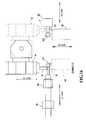
- FIG. 1 is a front elevation of a lathe according to a first embodiment of the present invention;
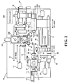
- FIG. 2 is a plan view of the lathe;
- FIG. 3 is a diagram showing an example of configuration of a turret and a tool rest shown in FIG. 1;
- FIG. 4 is a diagram showing an example of modification of the tool rest;
- FIG. 5 is an explanatory diagram of a machining example 1;
- FIG. 6 is an explanatory diagram of a machining example 2;
- FIG. 7 is an explanatory diagram of a machining example 3;
- FIG. 8 is an explanatory diagram of a machining example 4;
- FIG. 9 is an explanatory diagram of a machining example 5;
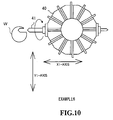
- FIG. 10 is an explanatory diagram of a machining example 6;
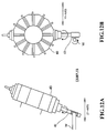
- FIGS. 11 are explanatory diagrams of a machining example 7;
- FIGS. 12 are explanatory diagrams of a machining example 8;
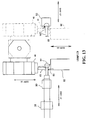
- FIG. 13 is an explanatory diagram of a machining example 9;
- FIG. 14 is an explanatory diagram of a machining example 10;
- FIG. 15 is an explanatory diagram of a machining example 11;
- FIG. 16 is an explanatory diagram of a machining example 12;
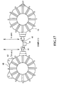
- FIG. 17 is an explanatory diagram of a machining example 13;
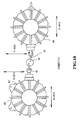
- FIG. 18 is an explanatory diagram of a machining example 14;
- FIG. 19 is a front elevation of a lathe according to a second embodiment of the present invention;
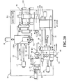
- FIG. 20 is a plan view of the lathe;
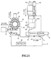
- FIG. 21 is a diagram showing an example of configuration of a tool spindle and a tool rest shown in FIG.19;
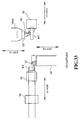
- FIG. 22 is a diagram showing an example of modification of the tool rest;
- FIG. 23 is an explanatory diagram of a machining example 15;
- FIG. 24 is an explanatory diagram of a machining example 16;
- FIG. 25 is an explanatory diagram of a machining example 17;
- FIG. 26 is an explanatory diagram of a machining example 18;
- FIG. 27 is an explanatory diagram of a machining example 19;
- FIG. 28 is an explanatory diagram of a machining example 20;
- FIGS. 29 are explanatory diagrams of a machining example 21;
- FIGS. 30 are explanatory diagrams of a machining example 22;
- FIG. 31 is an explanatory diagram of a machining example 23;
- FIG. 32 is an explanatory diagram of a machining example 24;
- FIG. 33 is an explanatory diagram of a machining example 25;
- FIG. 34 is an explanatory diagram of a machining example 26;
- FIG. 35 is an explanatory diagram of a machining example 27; and
- FIG. 36 is an explanatory diagram of a machining example 28.
-
- A lathe according to the first embodiment of the present invention will now be explained.
- This lathe is a machine that can apply complex machining to a work W. As shown in FIG. 1 and FIG. 2, the lathe comprise a
bed 10, amain spindle 30 for gripping the work W, aturret 40, and aback spindle 50 for gripping the work W. In addition, the lathe comprises acontroller 201 thereinside. Thecontroller 201 controls the lathe on the whole. - The
main spindle 30 has, for example, a chuck and grips the work W such that the centerline of the work W is oriented in a Z1-axis direction, which is one of the horizontal directions. Themain spindle 30 is rotatably supported by aheadstock 30A. Theheadstock 30A is mounted on tworails axis motor 13. The tworails bed 10 in parallel with the Z1-axis direction. Theheadstock 30A has a built-inwork rotation motor 31. Thework rotation motor 31 rotates the work gripped by themain spindle 30. Themain spindle 30 has ahole 30H through which work W penetrates, so that the work can be gripped by saidmain spindle 30 and can extend by penetrating through saidhole 30H. - The
turret 40 is rotatable about arotation axis 40K. Theturret 40 has a plurality oftools 41 attached thereto along its circumferential direction. Theturret 40 rotates and thereby moves a selectedtool 41 to a machining position where the work W is to be machined. According to the present embodiment, a position where the centerline of a selectedtool 41 becomes horizontal is the predetermined position. Theturret 40 has its position changed by a turret position setting mechanism to be explained later. Theturret 40 has an unillustrated built-in motor for rotating eachtool 41. - The turret position setting mechanism will now be explained with reference to FIG. 1, FIG. 2, and FIG. 3.
- The turret position setting mechanism comprises a
base 40A. Thebase 40A is mounted on tworails rails bed 10 in a Z2-axis direction that is parallel with the Z1-axis direction. By driving a Z2-axis motor 17, thebase 40A moves in the Z2-axis direction. - A
ball screw 40B is incorporated into thebase 40A such that it extends in an X1-axis direction which is one horizontal direction perpendicular to the Z2-axis. An X1-axis motor 18 for rotating theball screw 40B is provided at the end of theball screw 40B. - A
column 40C is provided on thebase 40A. Abracket 40J which is locked to theball screw 40B is attached to the bottom of thecolumn 40C. When the X1-axis motor 18 rotates, thecolumn 40C moves in the X1-axis direction. - A
ball screw 40D is incorporated into thecolumn 40C such that it extends in a Y1-axis direction, which is a direction of height perpendicular to the Z2-axis and X1-axis directions. A Y1-axis motor 40E is attached to the end of theball screw 40D. - A
bracket 40F is locked to theball screw 40D. Thebracket 40F is movable in the Y1-axis direction. Asupport unit 40G for supporting the rotation shaft of theturret 40 is rotatably attached to thebracket 40F. - The
support unit 40G has adirection change motor 40H and a tool selection motor 40I. - The
direction change motor 40H changes the direction of theturret 40 by rotating thesupport unit 40G in a plane including the Z2-axis and the X1-axis. The tool selection motor 40I makes the center axis of a selectedtool 41 horizontal by rotating theturret 40 about therotation axis 40K. - When the Y1-
axis motor 40E rotates, thebracket 40F and thesupport unit 40G move in the Y1-axis direction. As a result, the height of the centerline of thetool 41 which is selected to be made horizontal is shifted from the height of the centerline of the work W. - The above-described is the turret position setting mechanism.
- The
back spindle 50, for example, a chuck and grips the work W, while being opposed to themain spindle 30. Theback spindle 50 is supported by aback headstock 50A. Theback headstock 50A is mounted on tworails rails bed 10 such that they extend in a Z3-axis direction which is parallel with the Z1-axis direction. By driving a Z3-axis motor 22, theback headstock 50A moves in the Z3-axis direction along therails back headstock 50A has a built-inwork rotation motor 51. Thework rotation motor 51 rotates the work W gripped by theback spindle 50. Theback spindle 50 has ahole 50H through which work W penetrates, so that the work can be gripped by theback spindle 50 and can extend by penetrating through saidhole 50H. - The
main spindle 30 and theback spindle 50 have a hole formed therein, through which the work W penetrates. - The lathe further comprises a
tool rest 60, atool magazine 70, atool exchange mechanism 80, and aguide bush 90. - The
tool rest 60 is mounted on therails axis motor 24, thetool rest 60 moves in a Z4-axis direction which is parallel with the Z2-axis direction. An X2-axis motor 25 is provided at a side of thetool rest 60. The X2-axis motor 25 moves thetool rest 60 in an X2-axis direction which is parallel with the X1-axis direction. - The
tool rest 60 holds a plurality oftools 61 for machining the work W, and has aturret 62 as shown in FIG. 3. Thetools 61 are attached to theturret 62. Atool 61 corresponding to a rotation angle of theturret 62 is selected for machining. A Y2-axis motor 63 is attached to the top of thetool rest 60. The Y2-axis motor 63 changes the position of thetool rest 60 in a Y2-axis direction which is parallel with the Y1-axis direction, i.e., adjusts the height of thetool rest 60. - The
guide bush 90 is provided on themain spindle 30 at the side of theback spindle 50. Theguide bush 90 slidably supports a portion of the rotating work W that projects from themain spindle 30. - In the present embodiment, the
tool rest 60 comprises theturret 62. However, the present invention is not limited to this, but a plurality oftools 66 may be arrayed in asupport member 65 in a gang arrangement as shown in FIG. 4. FIG. 4 is a diagram showing a modified example of the tool rest. - The
tool magazine 70 contains the plurality oftools 41 to be attached to theturret 40. Thetool exchange mechanism 80 exchanges atool 41 attached to theturret 40 with atool 41 contained in thetool magazine 70. - The lathe having the above-described configuration has the
main spindle 30, theback spindle 50, and theguide bush 90. Accordingly, even when machining a lengthy work W, the lathe can prevent the work W from being bent and thus can apply a highly precise machining to the work W. Further, the lathe can machine the end surface of the work W. - Furthermore, the lathe can machine both end surfaces of the work W by cutting off the work W gripped by the
main spindle 30 by a tool attached to, for example, theturret 40, machining one end surface of the work W while gripping the work W by themain spindle 30, then gripping the work W by theback spindle 50 to machine the other end surface of the work W. Accordingly, the lathe can machine works having varied lengths from a short length to a long length, entirely without excluding both end surfaces thereof, into complex shapes. - Next, the outline of the control executed by the
controller 201 and the operation of the lathe will be explained along with explanation of examples of machining. - FIG. 5 is an explanatory diagram of a machining example 1 in which outer diameter machining is applied to both of a work W1 gripped by the
main spindle 30 and a work W2 gripped by theback spindle 50. - In a case where the works W1 and W2 gripped by the
main spindle 30 and backspindle 50 respectively are to be machined, thecontroller 201 selectstools 41 for outer diameter machining from the plurality oftools 41 attached to the turret 40 (step S101), and rotates the tool selection motor 40I such that the centerline of the selectedtools 41 horizontally faces the works W1 and W2 (step S102). Further, thecontroller 201 drives thedirection change motor 40H to rotate thesupport unit 40G, and adjusts the direction of theturret 40 in a horizontal plane such that the centerline of the selectedtool 41 becomes perpendicular to the centerline of the work W1 (step S103). - Then, by driving the Z1-
axis motor 13 or the Z2-axis motor 17, thecontroller 201 positions the portion of the work W1 to be machined in front of the tool 41 (step S104). Then, while rotating the work W1 by driving thework rotation motor 31, thecontroller 201 drives the Z1-axis motor 13 and the X1-axis motor 18 (step S105). That is, thecontroller 201 controls the Z1-axis motor 13 and the X1-axis motor 18 such that thetool 41 abuts on the work W1 and machines the outer circumference of the work W1 gripped by themain spindle 30. After finishing machining of thework W 1 gripped by themain spindle 30, thecontroller 201 drives the X1-axis motor 18 to retreat the turret 40 (step S106). - Then, the
controller 201 drives thedirection change motor 40H to rotate thesupport unit 40G by 180°, and at the same time, drives the tool selection motor 40I to rotate the direction of the selectedtool 41 by 180° (step S107). Then, by driving the Z3-axis motor 22 and the Z2-axis motor 17, thecontroller 201 positions the portion to be machined of the work W2 gripped by theback spindle 50 in front of the selected tool 41 (step S108). While rotating the work W2 by driving thework rotation motor 51, thecontroller 201 drives the Z3-axis motor 22 and the X1-axis motor 18 (step S109). - As a result, the selected
tool 41 abuts on the work W2, thereby machining the outer circumference of the work W2 gripped by theback spindle 50. Various kinds of machining are available depending on the kind of the selectedtool 41 and the manner of driving the Z1-axis motor 13, the Z2-axis motor 17, the Z3-axis motor 22, and the X1-axis motor 18, and the works W1 and W2 can be formed into a desired shape such as a linear shape, a tapered shape, a circular arc shape, etc. - FIG. 6 is an explanatory diagram of a machining example 2 in which hole drilling machining is applied to an end surface of both of a work W1 gripped by the
main spindle 30 and a work W2 gripped by theback spindle 50. - In this case, the
controller 201 selects a drill having a predetermined diameter from the plurality oftools 41 attached to theturret 40, as a machining tool 41 (step S201). Thecontroller 201 rotates the tool selection motor 40I such that the centerline of the selectedtool 41 becomes horizontal (step S202). Thecontroller 201 drives thedirection change motor 40H and rotates thesupport unit 40G such that the centerline of the selectedtool 41 becomes parallel with the centerline of the work W1, thereby adjusting the direction of theturret 40 in a horizontal plane (step S203). Then, thecontroller 201 drives the X1-axis motor 18 to move theturret 40 in the X1-axis direction, and make the tip of the selectedtool 41 face the end surface of the work W1 gripped by the main spindle 30 (step S204). Then, thecontroller 201 drives the Z1-axis motor 13 while rotating thework W 1 by driving thework rotation motor 31, and moves the tip of the selectedtool 41 toward the main spindle 30 (step S205). As a result, the selectedtool 41 cuts the end surface of the work W1 gripped by themain spindle 30, thereby drilling a hole in the work W 1 (step S206). - After finishing machining of the work W1 gripped by the
main spindle 30, thecontroller 201 drives the X1-axis motor 18 to retreat the turret 40 (step S207). Then, thecontroller 201 drives the tool selection motor 40I to rotate theturret 40 by 180° and make the tip of the selectedtool 41 turn to the end surface of the work W2 gripped by the back spindle 50 (step S208). Thecontroller 201 again drives the X1-axis motor 18 to make the selectedtool 41 face the end surface of the work W2 gripped by the back spindle 50 (step S209). Thecontroller 201 drives the Z3-axis motor 22 while rotating the work W2 by driving thework rotation motor 51, and moves the tip of the selectedtool 41 toward the back spindle 50 (step S210). Due to this, the selectedtool 41 cuts the end surface of the work W2 gripped by theback spindle 50, and a hole is drilled in the work W2 (step S211). - The outline of the case where hole drilling machining is applied to an end surface of both of the work W1 gripped by the
main spindle 30 and the work W2 gripped by theback spindle 50 has been described. However, it is possible to drill a hole in both end surfaces of one work W. - In this case, the
controller 201 controls the work W to be gripped by only the main spindle 30 (step S301). Then, thecontroller 201 applies hole drilling machining to the front end surface of the work W (step S302). When finishing hole drilling, thecontroller 201 drives the X1-axis motor 18 to retreat theturret 40 and the selected tool 41 (step S303). Then, by driving the Z3-axis motor 22, thecontroller 201 moves theback spindle 50 toward themain spindle 30 and controls theback spindle 50 to grip the end surface of the work W (step S304). After this, thecontroller 201 controls themain spindle 30 to release the work W (step S305), drives the Z3-axis motor 22 to move to a predetermined position (step S306), and returns theturret 40 and the selectedtool 41 to the machining position by driving the X1-axis motor 18 (step S307). Thereafter, by performing the same processes as described above, thecontroller 201 performs hole drilling in the back end surface of the work gripped by the back spindle 50 (step S308). - FIG. 7 is an explanatory diagram of a machining example 3 in which angled hole drilling is performed (a hole slanted with respect to the axis of the work W is drilled in the work W).
- In this case, the
controller 201 selects a drill from the plurality oftools 41 attached to theturret 40, as a machining tool (step S401). - The
controller 201 drives the tool selection motor 40I such that the centerline of the selectedtool 41 becomes horizontal (step S402). Thecontroller 201 drives thedirection change motor 40H to rotate thesupport unit 40G, and adjusts the direction of theturret 40 such that the centerline of the selectedtool 41 is at a desired angle with respect to the center axis of the work W (step S403). - Next, the
controller 201 drives the Z1-axis motor 13 or the Z2-axis motor 17 to bring the work W to a predetermined position (step S404). After this, thecontroller 201 drives the Z1-axis motor 13 and the X1-axis motor 18 while rotating the selectedtool 41, and moves the work W and the selectedtool 41 relatively with respect to each other such that the tip of the selectedtool 41 enters the work W at the desired angle with respect to the center axis of the work W (step S405). As a result, an angled hole is drilled in the work W gripped by themain spindle 30. - In a case where an angled hole is to be drilled in the work W gripped by the
back spindle 50, thecontroller 201 drives thedirection change motor 40H before drilling, in order to adjust the direction of theturret 40 such that the centerline of thetool 41 is at a desired angle with respect to the center axis of the work W gripped by the back spindle 50 (step S406). Next, thecontroller 201 drives the Z3-axis motor 22 or the Z2-axis motor 17 to bring the work W to a predetermined position (step S407). After this, thecontroller 201 concurrently drives the Z3-axis motor 22 and the X1-axis motor 18 while rotating the selectedtool 41, to move the work W and the selectedtool 41 relatively with respect to each other such that the tip of the selectedtool 41 enters the work W at the desired angle (step S408). As a result, an angled hole is drilled in the work W gripped by theback spindle 50. - FIG. 8 is an explanatory diagram of a machining example 4 where inner diameter machining is performed.
- In a case where inner diameter machining is to be applied to the work W1 gripped by the
main spindle 30 and the work W2 gripped by theback spindle 50, thecontroller 201 selects atool 41 for inner diameter machining from the plurality oftools 41 attached to theturret 40 as amachining tool 41, and performs the same processes as for drilling a hole in the end surface. - That is, the
controller 201 drives thedirection change motor 40H to rotate thesupport unit 40G such that the centerline of thetool 41 for inner diameter machining becomes parallel with the centerline of the work W1, and adjusts the direction of the turret 40 (step S501). Then, thecontroller 201 drives the X1-axis motor 18 to make the tip of the selectedtool 41 face the end surface of the work W1 gripped by the main spindle 30 (step S502). Next, while rotating the work W1 by driving thework rotation motor 31, thecontroller 201 drives the Z1-axis motor 13 to relatively move the tip of the selectedtool 41 toward the main spindle 30 (step S503). Due to this, the selectedtool 41 cuts the end surface of the work W1 gripped by themain spindle 30, thereby starting inner diameter machining of the work W1. Then, by driving the Z1-axis motor 13 and the X1-axis motor 18, the selectedtool 41 is moved in the Z1-axis direction and in the X1-axis direction, and a hole having a desired inner diameter is thereby formed in the work W1 gripped by themain spindle 30. - After finishing the machining of the work W1 gripped by the
main spindle 30, thecontroller 201 drives the X1-axis motor 18 to retreat the turret 40 (step S504). Thecontroller 201 drives the tool selection motor 40I to rotate the selectedtool 41 by 180° and make the tip of the selectedtool 41 face the end surface of the work W2 gripped by the back spindle 50 (step S505). Then, thecontroller 201 rotates the work W2 by driving thework rotation motor 51, and drives the Z3-axis motor 22 to move the tip of the selectedtool 41 toward the back spindle 50 (step S506). Then, by driving the Z3-axis motor 22 and the X1-axis motor 18, thecontroller 201 moves the selectedtool 41 in the Z3-axis direction and in the X1-axis direction, thereby cutting the end surface of the work W2 gripped by the back spindle 50 (step S507). Due to this, a hole having a desired inner diameter is formed in the end surface of the work W2 gripped by theback spindle 50. - FIG. 9 is an explanatory diagram of a machining example 5 in which the work W is cut linearly.
- In a case where the work W is to be formed into a D character shape by cutting a portion of the work W, an end mill is attached to the
turret 40 as amachining tool 41. Thecontroller 201 drives the tool selection motor 40I and rotates theturret 40 such that the centerline of the selectedtool 41 becomes horizontal. After this, thecontroller 201 drives the Y1-axis motor 40E while rotating the selectedtool 41, to move the selectedtool 41 in the Y1-axis direction, i.e., in the upward and downward direction, as shown in FIG. 9. Due to this, the work W is cut and the cross section of the work W becomes a D character shape. - FIG. 10 is an explanatory diagram of a machining example 6 in which an eccentric hole is drilled.
- In a case where an eccentric hole is formed in the work W by drilling a portion that is decentered from the centerline of the work W, a drill is attached to the
turret 40. Thecontroller 201 selects the drill as amachining tool 41, and drives the tool selection motor 40I to rotate theturret 40 such that the centerline of the selectedtool 41 becomes horizontal. Then, thecontroller 201 moves theturret 40 to a predetermined position by driving the Z2-axis motor 17, and thereafter, drives the Y1-axis motor 40E to move the centerline of the selectedtool 41 off from the height of the centerline of the work W . Next, while rotating the selectedtool 41, thecontroller 201 advances thetool 41 as shown in FIG. 10 by driving the X1-axis motor 18. As a result, an eccentric hole is formed in the work W. - FIG. 11A and FIG. 11B are explanatory diagrams of a machining example 7 in which the end portion of the work W is obliquely cut, where FIG. 11A shows a front elevation and FIG. 11 B shows a side elevation.
- In a case where the work W is to be obliquely cut, an end mill is attached to the
turret 40 as atool 41. Thecontroller 201 selects theend mill 41 as a machining tool (step S601), drives the tool selection motor 40I to rotate theturret 40 such that the centerline of the selectedtool 41 becomes horizontal (step S602). Then, by driving thedirection change motor 40H, thecontroller 201 adjusts the direction of theturret 40 such that the centerline of the selectedtool 41 is at a desired angle with respect to the centerline of the work W gripped by the main spindle 30 (step S603). Thecontroller 201 drives the Y1-axis motor 40E to move the selectedtool 41 in the Y1-axis direction (step S604). Due to this, theend mill 41 obliquely contacts the end portion of the work W, thereby obliquely cutting the end portion of the work W. - FIG. 12A and FIG. 12B are explanatory diagrams of a machining example 8 in which hob machining is applied to the work W, where FIG. 12A shows a front elevation and FIG. 12B shows a side elevation.
- In a case where hob machining for forming the work W into a toothed gear is performed, a hob is attached to the
turret 40 as atool 41. Thecontroller 201 selects the hob as a machining tool 41 (step S701), and drives the tool selection motor 40I to make the centerline of the hob horizontal (step S702). Next, thecontroller 201 moves theturret 40 to a predetermined position (step S703), and drives thedirection change motor 40H to adjust the direction of theturret 40 such that the centerline of the selected tool is at a predetermined angle with respect to the centerline of the work W (step S704). Then, thecontroller 201 advances the work W by driving the Z1-axis motor 13, while synchronously controlling the rotation of the selectedhob 41 and the rotation of the work W at a predetermined speed ratio (step S705). Due to this, the work W is moved while being cut by the selectedtool 41, and a toothed gear is formed on the work W. - FIG. 13 is an explanatory diagram of a machining example 9 in which outer diameter machining is applied to the work W by using a
tool 41 and atool 61. - In a case where outer diameter machining of the work W is performed by using the
tool 41 attached to theturret 40 and thetool 61 attached to thetool rest 60, an outer diameter machining tool is attached to theturret 40. Thecontroller 201 selects the outer diameter machining tool as a machining tool 41 (step S801), and drives the tool selection motor 40I to make the centerline of the selectedtool 41 horizontal (step S802). - The
controller 201 controls themain spindle 30, theback spindle 50, and theturret 40, in the same manner as for applying outer diameter machining to the work W by using only thetool 41. - On the other hand, an outer diameter machining tool is pre-attached to the
tool rest 60 as atool 61. As to thetool rest 60, thecontroller 201 rotates theturret 62 such that the selectedtool 61 faces the outer circumferential surface of the work W (step S803), drives the X2-axis motor 25 (step S804) to make thetool 61 cut the outer circumference of the work W. Due to this, the outer diameter of the work W is machined by thetool 41 and thetool 61. Thetool 41 and thetool 61 cut the work W while being positioned oppositely to each other with the work W placed therebetween. Accordingly, the work W is prevented from being fluctuated, and highly precise machining can be applied thereto. Further, since the outer diameter of the work W is machined by the twotools - FIG. 14 is an explanatory diagram of a machining example 10 in which hole drilling machining is applied to the work W by using the
tool 41 and thetool 61. - In a case where hole drilling machining is applied to the work W, drills are attached to the
turret 40 and thetool rest 60 respectively. Thecontroller 201 selects the drill on the tool rest 60 (step S901), and rotates theturret 62 such that the centerline of the selectedtool 61 horizontally faces the work W (step S902). Further, thecontroller 201 selects the drill on theturret 40 as a machining tool 41 (step S903), and drives the tool selection motor 40I such that the centerline of the selectedtool 41 horizontally faces the work W (step S904). - Next, the
controller 201 drives the Z2-axis motor 17 and the Z4-axis motor 24 to move the selectedtools tool 41 and thetool 61, thecontroller 201 drives the X1-axis motor 18 and the X2-axis motor 25 to advance thetool 41 and thetool 61 toward the work W (step S906). By advancing, thetool 41 and thetool 61 abut on the work W and cut it. Due to this, holes are formed symmetrically in the work W. - The
tool 41 and thetool 61 cut the work W while being positioned oppositely to each other with the work W placed therebetween. Accordingly, the work W can be prevented from being fluctuated, and highly precise machining can be applied thereto. Further, since the work W is machined by the twotools tool 41 is used for machining. - FIG. 15 is an explanatory diagram of a machining example 11 in which two works W1 and W2 are machined simultaneously.
- For example, in a case where machining for boring an eccentric hole in the end portion of the work W1 gripped by the
main spindle 30 is performed, and at the same time, outer diameter machining is applied to the work W2 gripped by theback spindle 50, an outer diameter machining tool is attached to theturret 40 and a drill is attached to thetool rest 60. - The
controller 201 selects the outer diameter machining tool from the plurality oftools 41 attached to theturret 40 as a machining tool 41 (step S1001), and controls the centerline of the selectedtool 41 to become horizontal at the same height as the work W2 gripped by theback spindle 50 and to face the work W2 in this state. Thecontroller 201 selects the drill on thetool rest 60 as amachining tool 61, and adjusts the selectedtool 61 such that its tip faces the portion to be machined of the work W1 gripped by themain spindle 30 by rotating theturret 62 and driving the X2-axis motor 25 (step S1002). Then, thecontroller 201 drives the X1-axis motor 18 to advance the selectedtool 41 to a predetermined position (step S1003). Further, thecontroller 201 controls the selectedtool 61 to advance toward the work W1 gripped by themain spindle 30 by driving the Z1-axis motor 13 while rotating thetool 61. As a result, an eccentric hole (a hole bored at a position decentered from the center of the work W1) is bored in the end portion of the work W1 gripped by themain spindle 30. - In parallel with these operations, the
controller 201 drives thework rotation motor 51 to rotate the work W2, and drives the X3-axis motor 22 to advance the work W2 (step S1004). Due to this, the outer circumferential surface of the work W2 gripped by theback spindle 50 is cut. - FIG. 16 is an explanatory diagram of a machining example 12 in which two works W1 and W2 are machined simultaneously.
- A desired
machining tool 41, for example, an outer shape machining tool is attached to theturret 40, and a desiredmachining tool 61, for example, an outer shape machining tool is attached to thetool rest 60. - As shown by solid lines, the work W1 gripped by the
main spindle 30 is machined by thetool 41 attached to theturret 40, and the work W2 gripped by theback spindle 50 is simultaneously machined by thetool 61 attached to thetool rest 60. - Further, the work W1 gripped by the
main spindle 30 is machined by thetool 41 attached to theturret 40 and thetool 61 attached to thetool rest 60 as shown by solid lines and one-dot dashed lines, and before or after this, the work W2 gripped by theback spindle 50 is machined by thetool 41 attached to theturret 40 and thetool 61 attached to thetool rest 60 as shown by solid lines and one-dot dashed lines. - FIG. 17 is an explanatory diagram of a machining example 13 in which a "wrench application unit" is formed on the work W.
- In a case where a "wrench application unit" is formed on the work W, end mills are attached to the
turret 40 and to theturret 62 of thetool rest 60. Thecontroller 201 selects these end mills asmachining tools 41 and 61 (step S1101), and makes the centerlines of thetools - The
controller 201 moves thetools controller 201 drives the Y1-axis motor 40E and the Y2-axis motor 63 to move thetools controller 201 may repeat the operation of moving thetools - FIG. 18 is an explanatory diagram of a machining example 14 in which eccentric orifices are formed in two positions of the work W.
- In a case where eccentric holes are formed in two positions of the work W, drills are attached to the
turret 40 and theturret 62 of thetool rest 60. Thecontroller 201 selects these drills asmachining tools 41 and 61 (step S1201), and makes the centerlines of the selectedtools controller 201 moves thetools axis motor 17 and the Z4-axis motor 24 (step S1203). Then, thecontroller 201 drives the Y1-axis motor 40E and the Y2-axis motor 63 to adjusting thetools controller 201 advances thetools axis motor 18 and the X2-axis motor 25 (step S1205). As a result, the work W is bored and two eccentric holes are formed simultaneously. - The lathe according to the present invention has the following effects.
- (1) The lathe according to the present embodiment comprises the
main spindle 30, theturret 40, theback spindle 50, and theguide bush 90. Accordingly, when the lathe applies machining to a lengthy work W, it prevents the work W from being bent, enabling a highly precise machining. Further, this lathe can apply machining to the end surface of the work W. Furthermore, this lathe can apply machining to both end surfaces of the work W by once cutting off the work W gripped by themain spindle 30, and after this handing the work W gripped by themain spindle 30 to theback spindle 50. Therefore, this lathe can apply machining to works having varied length from short length to long length, entirely without excluding both end surfaces thereof, into complex shapes. - (2) The work W1 gripped by the
main spindle 30 and the work W2 gripped by theback spindle 50 can both be machined without the lathe being stopped. - (3) Since the work W1 gripped by the
main spindle 30 and the work W2 gripped by theback spindle 50 can be machined by acommon tool 41, there is no need of preparing a same kind of tool in a plural number. - (4) Since the lathe comprises the
tool magazine 70, it is possible to prepare plural kinds oftools 41 in advance. - (5) Since the lathe comprises the
tool exchange mechanism 80, it is possible to exchangetools 41 without stopping the lathe. - (6) The
turret 40 can be moved in the Y1-axis direction. Therefore, the position of thetool 41 is movable three-dimensionally, enabling complicated machining such as boring an eccentric hole or an angled hole in the work W, hob machining, etc. - (7) Since the
tool rest 60 is provided, a tool to be used next can be prepared at thetool rest 60 while other machining is applied by using, for example, thetool 41 on theturret 40. - (8) Since machining can be applied by using the
tool 41 and thetool 61 simultaneously, machining time can be shortened. - (9) Since machining can be applied by using the
tool 41 and thetool 61 simultaneously, one can be used for rough machining and the other can be used for finishing machining. - (10) Since machining can be applied by using the
tool 41 and thetool 61 simultaneously, different portions of the work W can be machined simultaneously. - (11) Since a plurality of
tools 41 can be attached to theturret 40, there is no need of stopping the lathe each time thetools 41 are exchanged, resulting in a high machining efficiency. - (12) Since the
back spindle 50 is provided with a hole through which the work W penetrates, a further lengthy work W can be attached to the lathe. This eliminates the need of upsizing the lathe. -
- FIG. 19 is a front elevation of a lathe according to the second embodiment of the present invention. FIG. 20 is a plan view of the lathe. FIG. 21 is a diagram showing an example of configuration of a tool spindle and a tool rest shown in FIG. 19. In these FIGS. 19 to 21 and FIGS. 22 to 36 to be mentioned later, same reference numerals as those used in the first embodiment are used for same elements as those in the first embodiment.
- This lathe is a machine capable of applying complex machining to a work W. As shown in FIG. 19 and FIG. 20, the lathe comprises a
bed 10, amain spindle 30 for gripping the work W, atool spindle 100, aback spindle 50 for gripping the work W, and acontroller 201. Thecontroller 201 controls the entire lathe. - A
headstock 30A supporting themain spindle 30 is mounted on tworails bed 10 in parallel with a Z1-axis direction. Therails bed 10 so as to extend in parallel with the Z1-axis direction. Theheadstock 30A is designed so as to move on therails axis motor 13. Theheadstock 30A has a built-inwork rotation motor 31. Thework rotation motor 31 rotates the work W gripped by themain spindle 30. - The
tool spindle 100 rotatably grips anexchangeable tool 101. Thetool spindle 100 is supported by atool headstock 100A. - The
tool headstock 100A is mounted on tworails rails bed 10 so as to extend in a Z2-axis direction parallel with the Z1-axis direction. By driving a Z2-axis motor 17, thetool headstock 100A moves on therails - An X1-
axis motor 18 which moves thetool headstock 100A in an X1-axis direction perpendicular to the Z2-axis direction is provided at a side of thetool headstock 100A. Adirection change motor 103 and a Y1-axis motor 102 are attached to the upper portion of thetool headstock 100A. Thedirection change motor 103 changes the direction of atool 101 by rotating thetool headstock 100A. The Y1-axis motor 102 changes the position of thetool headstock 100A in a Y1-axis direction (direction of height) perpendicular to the Z2-axis direction and the X1-axis direction. - The
back spindle 50 grips the work W while being opposed to themain spindle 30. Theback spindle 50 is supported by aback headstock 50A. Theback headstock 50A is mounted on tworails bed 10 in a Z3-axis direction parallel with the Z1-axis direction. Therails bed 10 so as to extend in a Z3-axis direction parallel with the Z1-axis direction. Theback headstock 50A is designed so as to move in the Z3-axis direction by driving a Z3-axis motor 22. Awork rotation motor 51 is built in theback headstock 50A. Thework rotation motor 51 rotates the work W gripped by theback spindle 50. - The
main spindle 30 and theback spindle 50 have a hole formed therein, through which the work W penetrates. The lathe further comprises atool rest 60, atool magazine 70, atool exchange mechanism 80, and aguide bush 90. - The
tool rest 60 is mounted onrails tool rest 60 is designed so as to move in a Z4-axis direction parallel with the Z2-axis direction, by driving a Z4-axis motor 24. An X2-axis motor 25 which moves thetool rest 60 in an X2-axis direction parallel with the X1-axis direction is provided at a side of thetool rest 60. - The
tool rest 60 holds a plurality oftools 61 for machining the work W. Thetool rest 60 has aturret 62, as shown in FIG. 21. Thetools 61 are attached to theturret 62. Atool 61 corresponding to a rotation angle of theturret 62 is selected for machining. A Y2-axis motor 63 is attached to the upper portion of thetool rest 60. The Y2-axis motor 63 changes the position of thetool rest 60 in a Y2-axis direction (direction of height) parallel with the Y1-axis direction. - The
guide bush 90 is provided on themain spindle 30 at a side of theback spindle 50. Theguide bush 90 slidably supports a portion of the work W that projects from themain spindle 30. - In the present embodiment, the
tool rest 60 has theturret 62. However, the present invention is not limited to this, but a plurality oftools 66 may be arrayed in asupport member 65 in a gang arrangement, as shown in FIG. 22. FIG. 22 is a diagram showing a modified example of the tool rest. - The
tool magazine 70 contains a necessary number oftools 101 to be attached to thetool spindle 100. Thetool exchange mechanism 80 comprises a mechanism for exchanging an arbitrary one of a plurality oftools 101 attached to thetool spindle 100, with any of thetools 101 contained in thetool magazine 70. - Next, the operation of the lathe will be explained along with explanation of examples of machining.
- FIG. 23 is an explanatory diagram of a machining example 15 in which outer diameter machining is applied to both of a work W1 gripped by the
main spindle 30 and a work W2 gripped by theback spindle 50. - In this case, the
main spindle 30 grips the work W1 and theback spindle 50 grips the work W2. - Next, the
controller 201 positions the portion to be machined of the work W1 gripped by themain spindle 30 in front of thetool spindle 100, by driving the Z1-axis motor 13 and the Z2-axis motor 17 (step S 1301). - The
controller 201 drives the Z1-axis motor 13 and the X1-axis motor 18 while rotating the work W1 by driving the work rotation motor 31 (step S1302). As a result, thetool 101 abuts on the work W1, thereby machining the outer circumference of the work W1 gripped by themain spindle 30. Thecontroller 201 retreats thetool spindle 100 by driving the X1-axis motor 18, after machining of the work W1 is finished (step S1303). - Then, the
controller 201 rotates thetool 101 of thetool spindle 100 by 180° (step S1304). Then, by driving the Z3-axis motor 22 and the Z2-axis motor 17, thecontroller 201 positions the portion to be machined of the work W2 gripped by theback spindle 50 in front of the tool spindle 100 (step S1305). Next, thecontroller 201 rotates the work W2 by driving the work rotation motor 51 (step S 1306), and drives and controls the Z3-axis motor 22 and the X1-axis motor 18 (step S1307). As a result, thetool 101 abuts on the work W2, thereby machining the outer circumference of the work W2 gripped by theback spindle 50. - The
controller 201 applies various machining to the work W1 and the work W2 by appropriately managing the kinds oftools 11, the Z1-axis motor 13, the Z2-axis motor 17, the Z3-axis motor 22, and the X1-axis motor 18. For example, the work W1 and the work W2 are machined to have a linear outer circumference, or to have a tapered shape, or to have an outer circumference having a desired shape such as a circular arc shape, etc. - FIG. 24 is an explanatory diagram of a machining example 16 in which a hole is drilled in the end surface of both of the work W1 gripped by the
main spindle 30 and the work W2 gripped by theback spindle 50. - In this case, the
tool 101 to be attached to thetool spindle 100 is a drill. - The
controller 201 drives the X1-axis motor 18 and thedirection change motor 103 to control the tip of thetool 101 to face the end surface of the work W1 gripped by the main spindle 30 (step S1401). Next, while rotating the work W1 by driving thework rotation motor 31, thecontroller 201 drives the Z1-axis motor 13 so that the tip of thetool 101 advances toward the main spindle 30 (step S1402). Due to this, thetool 101 drills the end surface of the work W1, thereby drilling a hole in the end surface of the work W1. - After machining of the work W1 at the side of the
main spindle 30 is finished, thecontroller 201 drives the X1-axis motor 18 to retreat the tool spindle 100 (step S1403). Then, thecontroller 201 drives thedirection change motor 103 to control the tip of thetool 101 to face the end surface of the work W2 gripped by the back spindle 50 (step S1404). Then, while rotating the work W2 by driving thework rotation motor 51, thecontroller 201 drives the Z3-axis motor 22 so that the tip of thetool 101 advances toward the back spindle 50 (step S1405). Due to this, thetool 101 abuts on the end surface of the work W2 to drill the end surface, thereby drilling a hole in the work W2. - The above explanation shows the outline of the case where hole drilling machining is applied to the end surface of both of the work W1 gripped by the
main spindle 30 and the work W2 gripped by theback spindle 50. However, a hole can be drilled in both end surfaces of one work W. - In this case, the
controller 201 first causes the work W to be gripped by the main spindle 30 (step S1401). Next, thecontroller 201 controls thetool 101 to drill a hole in one end surface of the work W (step S1402). When hole drilling is finished, thecontroller 201 drives the X1-axis motor 18 to retreat thetool spindle 100, and drives the Z3-axis motor 22 to move theback spindle 50 toward themain spindle 30 so that the end portion of the work W is gripped by the back spindle 50 (step S1403). After this, thecontroller 201 controls themain spindle 30 to release the work W (step S1404). Next, thecontroller 201 drives the Z3-axis motor 22 to move theback spindle 50 to a predetermined position (step S1405), and drives the X1-axis motor 18 to return thetool spindle 100 to the machining position (step S1406). After this, thetool 101 drills a hole in the other end surface of the work W in the same way as described above (step S 1407). - FIG. 25 is an explanatory diagram of a machining example 17 in which an "angled hole" is formed in the work.
- In this case, the
tool 101 to be attached to thetool spindle 100 is a drill. - Before the work W1 gripped by the
main spindle 30 is machined, thecontroller 201 drives thedirection change motor 103 to control thetool 101 to be at a desired angle to the axis of the work W1 gripped by the main spindle 30 (step S1501). - Next, the
controller 201 drives the Z1-axis motor 13 or the Z2-axis motor 17 to adjust the relative positions of the work W1 and thetool 101 with respect to each other (step S1502). After this, while rotating thetool 101, thecontroller 201 simultaneously drives the Z1-axis motor 13 and the X1-axis motor 18 to relatively move the work W1 and thetool 101 in a manner that the tip of thetool 101 enters thework W 1 at the desired angle to the axis of the work W1 (step S1503). Due to this, an angled hole is drilled in the work W1 gripped by themain spindle 30. - In a case where an angled hole is drilled in the work W2 gripped by the
back spindle 50, thecontroller 201 controls thedirection change motor 103 in a manner that thetool 101 is at a desired angle to the axis of the work W2 (step S1504). Next, thecontroller 201 drives the Z3-axis motor 22 or the Z2-axis motor 17 to adjust the relative positions of thetool 101 and the work W2 with respect to each other (step S1505). After this, while rotating thetool 101, thecontroller 201 synchronously drives the Z3-axis motor 22 and the X1-axis motor 18 to relatively move the work W2 and thetool 101 in a manner that the tip of thetool 101 enters the work W2 at the desired angle (step S1506). Due to this, an angled hole is drilled in the work W2. - FIG. 26 is an explanatory diagram of a machining example 18 in which a hole having a desired diameter is formed in the work W (inner diameter machining is applied to the work W).
- In a case where inner diameter machining is applied to the work W1 gripped by the
main spindle 30 and the work W2 gripped by theback spindle 50, thecontroller 201 performs the same process as applying hole drilling machining to an end surface, with an inner diameter machining tool attached to thetool spindle 100 as thetool 101. That is, thecontroller 201 controls the X1-axis motor 18 and thedirection change motor 103 such that thetool 101 and the work W1 gripped by themain spindle 30 becomes coaxial and the tip of thetool 101 faces the end surface of the work W1 gripped by the main spindle 30 (step S1601). Next, thecontroller 201 drives the Z1-axis motor 13 or the Z2-axis motor 17 to move the tip of thetool 101 toward themain spindle 30 while rotating the work W1 by driving the work rotation motor 31 (step S1602). Thecontroller 201 controls the Z1-axis motor 13 and the X1-axis motor 18 to move thetool 101 in the Z1-axis direction and the X1-axis direction and form a hole in the end surface of the work W1 by cutting the work W1, and adjusts the diameter and the depth of the hole (step S1603). - After machining of the work W2 is finished, the
controller 201 drives the X1-axis motor 18 to retreat the tool spindle 100 (step S1604). - Subsequently, the
controller 201 drives thedirection change motor 103 to rotate thetool spindle 100 by 180° so that the tip of thetool 101 faces the end surface of the work W2 gripped by the back spindle 50 (step S1605). Then, thecontroller 201 drives thework rotation motor 51 to rotate the work W2 and drives the Z3-axis motor 22 or the Z2-axis motor 17 to relatively move the tip of thetool 101 toward the back spindle 50 (step S1606). Then, by controlling the Z3-axis motor 22 and the X1-axis motor 18, thecontroller 201 moves thetool 101 in the Z3-axis direction and the X1-axis direction to form a hole in the work W2, and adjusts the depth, diameter, and position of the hole (step S1607). - FIG. 27 is an explanatory diagram of a machining example 19 in which the work W is cut linearly.
- In a case where a portion of the work W is cut to form the cross section of the work W into a D character shape, an end mill is attached to the
tool spindle 100 as thetool 101. Thecontroller 201 moves thetool spindle 100 to a predetermined position (step S1701). After this, thecontroller 201 drives the Y1-axis motor 102 to move the end mill in the Y1-axis direction while rotating the tool 101 (step S1702). In accordance with necessity, thecontroller 201 moves thetool spindle 100 in the Z2-axis direction (the direction of axis of the work W) (step S1703). Due to this, the work W is cut and the cross section of the work W becomes a D character shape. - FIG. 28 is an explanatory diagram of a machining example 20 in which an eccentric hole is formed in the work W.
- In a case where a hole (eccentric hole) is formed in a position decentered from the center axis of the work W, a drill is attached to the
tool spindle 100 as thetool 101. Thecontroller 201 drives the Z2-axis motor 17 to move thetool spindle 100 to a predetermined position (step S1801). Then, thecontroller 201 drives the Y1-axis motor 102 to make the height of thetool 101 differ from the height of the center of the work W (step S1802). Then, while rotating thetool 101, thecontroller 201 drives the X1-axis motor 18 to advance thetool 101 and form a hole in the work W (step S 1803). Due to this, an eccentric hole is formed in the work W. - FIGS. 29A and 29B are explanatory diagrams of a machining example 21 in which the end portion of the work is obliquely cut, where FIG. 29A shows a front elevation and FIG. 29B shows a side elevation.
- In a case where the end portion of the work W is obliquely cut, an end mill is attached to the
tool spindle 100 as thetool 101. Thecontroller 201 drives thedirection change motor 103 such that thetool 101 is at a desired angle to the axis of the work W gripped by the main spindle 30 (step S1901). Then, thecontroller 201 drives the Y1-axis motor 102 to move thetool 101 in the Y1-axis direction (step S1902). Due to this, thetool 101 obliquely abuts on the end portion of the work W, thereby cutting the end portion of the work W obliquely. In accordance with necessity, thecontroller 201 moves thetool spindle 100 and the work W relatively in the X-axis direction and Z-axis direction. - FIGS. 30A and 30B are explanatory diagrams of a machining example 22 in which hob machining is applied to the work W, where FIG. 30A shows a front elevation and FIG. 30B shows a side elevation.
- In a case where hob machining for forming a toothed gear is applied, a hob is attached to the
tool spindle 100 as thetool 101. Thecontroller 201 moves thetool spindle 100 to a predetermined position (step S2001). Then, thecontroller 201 drives thedirection change motor 103 to make thetool 101 to be at a predetermined angle (step S2002). - The
controller 201 controls the rotation of thetool 101 and the rotation of the work W to be synchronous with each other at a predetermined speed ratio, and advances the work W by driving the Z1-axis motor 13 (step S2003). Due to this, the work W moves while being cut by thetool 101, and a toothed gear is formed on the work W. - FIG. 31 is an explanatory diagram of a machining example 23 in which outer diameter machining is applied to the work W using the
tool 101 and thetool 61. - In a case where outer diameter machining is applied to the work W by using the
tool 101 attached to thetool spindle 100 and thetool 61 attached to thetool rest 60, an outer diameter machining tool is attached to thetool spindle 100 as thetool 101 and an outer diameter machining tool is selected as thetool 61. - The
controller 201 controls themain spindle 30, theback spindle 50, and thetool spindle 100, in the same manner as for applying outer diameter machining to the work W using only thetool 101. - The
controller 201 controls thetool rest 60 such that theturret 62 rotates and the selectedtool 61 faces the outer circumferential surface of the work W, and drives the X2-axis motor 25 such that thetool 61 cuts the outer circumference of the work W. Thetool 101 and thetool 61 cut the work W while being opposed to each other with the work W positioned therebetween. Accordingly, the work W is prevented from being fluctuated and a highly precise machining can be applied thereto. Further, since the outer diameter of the work W is machined by the twotools - FIG. 32 is an explanatory diagram of a
machining tool 24 in which hole drilling machining is applied to the work W. - In a case where hole drilling machining is applied to the work W, a drill is attached to the
tool spindle 100 as thetool 101, and a drill is selected as thetool 61 of thetool rest 60. Thecontroller 201 rotates theturret 62 to make the selectedtool 61 face the work W (step S2011). Then, thecontroller 201 drives the Z2-axis motor 17 and the Z4-axis motor 24 to move thetool 101 and thetool 61 to predetermined positions (step S2012). After this, while rotating thetool 101 and thetool 61, thecontroller 201 drives the X1-axis motor 18 and the X2-axis motor 25 to advance thetool 101 and thetool 61 toward the work W so that the work W is cut by thetool 101 and the tool 61 (step S2013). Due to this, holes are symmetrically formed in the work W. Thetool 101 and thetool 61 cut the work W while being opposed to each other with the work W positioned therebetween. Accordingly, the work W is prevented from being fluctuated, and a highly precise machining is available. Further, since the work W is machined by the twotools 101ad 61 simultaneously, the total machining time can be shorter than a case where machining is applied by using only the tool. 101. - FIG. 33 is an explanatory diagram of a machining example 25 in which two works W1 and W2 are machined simultaneously.
- For example, in a case where machining for forming an eccentric hole is applied to the end surface of the work W1 gripped by the
main spindle 30 and outer diameter machining is applied to the work W2 gripped by theback spindle 50, an outer diameter machining tool is attached to thetool spindle 100 as thetool 101. - The
controller 201 drives the X1-axis motor 18 to advance thetool 101 to a predetermined position (step S2101). Thecontroller 201 rotates theturret 62 to select a drill as thetool 61 of the tool rest 60 (step S2102). Next, thecontroller 201 drives the X2-axis motor 25 to adjust the selectedtool 61 such that its tip faces the portion of the work W1 that is to be machined (step S2103). Then, while rotating thetool 61, thecontroller 201 drives the Z1-axis motor 13 to advance the work W1 gripped by the main spindle 30 (step S2104). - Along with this process, the
controller 201 rotates the work W2 by driving thework rotation motor 51 and drives the Z3-axis motor 22 to advance the work W2 gripped by the back spindle 50 (step S2105). Due to this, an eccentric hole is formed in the end surface of the work W1 and the outer circumferential surface of the work W2 is cut. - FIG. 34 is an explanatory diagram of a machining example 26 in- which the two
works W 1 and W2 are machined simultaneously. - For example, in a case where outer diameter machining is applied to the work W2 gripped by the
main spindle 30 and the work W2 gripped by theback spindle 50, thetool 101 attached to thetool spindle 100 and thetool 61 attached to thetool rest 61 may simultaneously apply machining to one work W, or thetool 101 and thetool 61 may independently apply machining to the work W1 and the work W2 respectively. - FIG. 35 is an explanatory diagram of a machining example 27 in which a wrench application unit is formed on the work W.
- In a case where a wrench application unit is formed on the work W, an end mill is attached to the
tool spindle 100 as thetool 101. Thecontroller 201 selects an end mill as thetool 61 of the tool rest 60 (step S2201). After this, thecontroller 201 moves thetools axis motor 102 and the Y2-axis motor 63 to move thetool 101 and thetool 61 in the Y1-axis direction and the Y2-axis direction respectively (step S2202). Due to this, the both sides of the work W are cut and a wrench application unit is formed. - FIG. 36 is an explanatory diagram of a machining example 28 in which eccentric holes are formed in the work W.
- In a case where eccentric holes are formed in two portions of the work W, a drill is attached to the
tool spindle 100 as thetool 101. Thecontroller 201 selects a drill as thetool 61 of thetool rest 60. Thecontroller 201 moves thetool 101 and thetool 61 to predetermined positions in the Z2-axis direction and the Z4-axis direction. After this, thecontroller 201 drives the Y1-axis motor 102 and the Y2-axis motor 63 to adjust thetool 101 and thetool 61 to be at predetermined positions in the Y1-axis direction and the Y2-axis direction. Next, thecontroller 201 advances thetool 101 and thetool 61 by driving the X1-axis motor 18 and the X2-axis motor 25. Due to this, hole drilling machining is applied to the work W and two eccentric holes are simultaneously formed. - As described above, the lathe according to the present embodiment has the following operation effects.
- (1) Since the lathe comprises the
main spindle 30, thetool spindle 100, theback spindle 50, and theguide bush 90, even when a lengthy work W is machined, it can be prevented from being bent. Accordingly, highly precise machining is available. Further, an end surface of the work W can be machined. Furthermore, both end surfaces of the work W can be machined by machining the work W gripped by themain spindle 30, and after this machining is finished, by machining the work W by moving the work W from themain spindle 30 to theback spindle 50. Therefore, it is possible to machine works W having varied lengths from a short length to a long length, entirely without excluding both end surfaces thereof, into complex shapes. - (2) It is possible to machine the work W1 gripped by the
main spindle 30 and the work W2 gripped by theback spindle 50 without stopping the lathe. - (3) The
tool spindle 100 grips onetool 101. Accordingly, unlike theturret 40 in the first embodiment, no interference occurs betweenadjacent tools 41. - (4) The work W2 gripped by the
main spindle 30 and the work W2 gripped by theback spindle 50 can be both machined by thesame tool 101. Therefore, there is no need of preparing a same kind oftool 101 in a plural number. - (5) The lathe comprises the
tool magazine 70. Accordingly, it is possible to prepare plural kinds oftools 101 in advance. - (6) The lathe comprises the
tool exchange mechanism 80. Accordingly, it is possible to exchange thetools 101 without stopping the lathe. - (7) The lathe can move the
tool spindle 100 in the Y1-axis direction. Accordingly, it is possible to freely move thetool 101 three-dimensionally. Therefore, complex machining such as machining for drilling an eccentric hole in the work W, machining for forming an angled hole, hob machining, etc. becomes available. - (8) The lathe comprises the
tool rest 60. Therefore, the lathe can prepare a tool to be used next on thetool rest 60, while, for example, applying machining by using thetool 101 on thetool spindle 100. Crosswise, the lathe can prepare a tool to be used next on thetool spindle 100, while, for example, applying machining by using thetool 61 on thetool rest 60. This shortens the idle time for exchanging tools. - (9) The lathe can apply machining to the work W by simultaneously using the
tool 101 and thetool 61. Accordingly, the machining time can be shortened. - (10) Since machining can be applied by simultaneously using the
tool 101 and thetool 61, one can be used for rough machining and the other can be used for finishing machining. - (11) Since machining can be applied by simultaneously using the
tool 101 and thetool 61, different portions of the work W can be machined simultaneously. - (12) Since the
back spindle 50 has a hole formed therein, through which the work W penetrates, a lengthy work W can be attached thereto. Due to this, there is no need of upsizing the lathe. -
- The present invention is not limited to the above-described embodiments, but may be variously modified. Modified examples include the followings.
- (i) According to the above-described embodiments, the X1- and X2-axis directions, the Z1-, Z2-, Z3-, and Z4-axis directions, and the Y1- and Y2-axis directions are perpendicular to one another. However, they may not be perpendicular to each other as long as they are different directions.
- (ii) According to the above-described embodiments, the X1-axis direction and the
X2-axis direction are parallel with each other, and the Y1-axis direction and the Y2-axis
direction are parallel with each other. However, they may not be parallel. For example,
the
turret 40 or thetool spindle 100 may be structured to obliquely fall from an upper position to a lower position to move thetool 41 or thetool 101 forward. Furthermore, symmetrically with theturret 40 or thetool spindle 100, thetool rest 60 may be structured to obliquely fall from an upper position to a lower position to move thetool 61 forward. - (iii) Machining may be applied to the work W by fixing the position of the
turret 40, thetool spindle 100, or thetool rest 60 and moving themain spindle 30 or theback spindle 50. Crosswise, machining may be applied to the work W by fixing the position of themain spindle 30 or theback spindle 50 and moving theturret 40, thetool spindle 100, or thetool rest 60. -
- Various embodiments and changes may be made thereunto without departing from the broad spirit and scope of the invention. The above-described embodiments are intended to illustrate the present invention, not to limit the scope of the present invention. The scope of the present invention is shown by the attached claims rather than the embodiments. Various modifications made within the meaning of an equivalent of the claims of the invention and within the claims are to be regarded to be in the scope of the present invention.
Claims (16)
- A lathe characterized by comprising:a main spindle (30) which grips and rotates a work (W), and is reciprocatable in a Z direction which is parallel with an axis of rotation of said work (W);a back spindle (50) which is positioned oppositely to said main spindle (30), grips and rotates a work (W), and is reciprocatable in the Z direction;a tool holding member (40, 100) which has a tool (41, 101) for machining said work attached thereto, is reciprocatable in the Z direction and also reciprocatable in an X direction different from the Z direction, and rotates in an X-Z plane including the Z direction and the X direction to change a direction of said tool; anda guide bush (90) which rotatably supports said work projecting from said main spindle (30), and slides said work in a direction of axis of said work.
- The lathe according to claim 1,
characterized in that said tool holding member (40) has a plurality of tools for machining said work attached thereto, and is so structured as to position a tool selected from said plurality of tools at a predetermined position at which said work is to be machined. - The lathe according to claim 1,
characterized in that said tool holding member (40) is constituted by a turret which has a plurality of tools for machining said work attached thereto and positions a tool, of said plurality of tools, that is to be used for machining at a predetermined position at which said work is to be machined. - The lathe according to claim 1,
characterized in that said tool holding member (100) is constituted by a tool spindle to which a tool for machining said work is attached. - The lathe according to claim 1, characterized by further comprising:a tool magazine (70) which contains a plurality of tools; anda tool exchange mechanism (80) which exchanges said attached tool to a tool contained in said tool magazine (70).
- The lathe according to claim 1,
characterized in that said main spindle (30) comprises a hole (30H) through which said work penetrates, so that said work can be gripped by said main spindle (30) and can extend by penetrating through said hole. - The lathe according to claim 1,
characterized in that said back spindle (50) comprises a hole (50H) through which said work penetrates, so that said work can be gripped by said back spindle (50) and can extend by penetrating through said hole. - The lathe according to claim 1,
characterized in that said tool holding member (40, 100) is reciprocatable in the Z direction (Z2-axis direction) and the X direction (X1-axis direction), and is also reciprocatable in a Y direction which is different from the Z and X directions. - The lathe according to claim 1, characterized by further comprising
a tool rest (60) which has one or a plurality of tools mounted thereon, and works independently from said tool holding member to machine said work gripped by said main spindle (30) or by said back spindle (50) by using said mounted tool. - The lathe according to claim 9,
characterized in that said tool rest (60) is movable in the X direction, the Z direction, and the Y direction. - The lathe according to claim 1, characterized by further comprising
a controller (201) which controls positions of said main spindle (30) and said back spindle (50) and work gripping and work rotation by said spindles (30, 50), and controls a position and direction of said tool holding member (40, 100). - The lathe according to claim 1,
characterized in that said main spindle (30) and said back spindle (50) can independently grip works respectively, and can grip one work in cooperation with each other. - A lathe characterized by comprising:first spindle means (30) for gripping a work (W) to rotate said work about a predetermined rotation axis which extends in a Z direction, and to move said work in parallel with said rotation axis;guide bush means (90) for supporting said work gripped by said first spindle means (30);second spindle means (50) for gripping a work (W) coaxially with said first spindle means (30) to rotate said work about said rotation axis and to move said work in parallel with said rotation axis; anda tool holding means (40, 100) which is reciprocatable in the Z direction and also reciprocatable in an X direction different from the Z direction, and rotates in an X-Z plane including the Z direction and the X direction to change a direction of a tool to make the tool machine said work.
- The lathe according to claim 13,
characterized in that said first spindle means (3 0) and said second spindle means (50) can independently grip works respectively, and can grip one work in cooperation with each other. - The lathe according to claim 13,
characterized in that said tool holding means includes means which has a plurality of tools for machining said work attached thereto, and positions a tool selected from said plurality of tools at a predetermined position at which said work is to be machined. - The lathe according to claim 13, characterized by further comprising;
means which holds a tool and machines one or a plurality of works gripped by said first spindle means (30) and/or said second spindle means (50).
Applications Claiming Priority (4)
| Application Number | Priority Date | Filing Date | Title |
|---|---|---|---|
| JP2003346249 | 2003-10-03 | ||
| JP2003346249 | 2003-10-03 | ||
| JP2004219722A JP2005125482A (en) | 2003-10-03 | 2004-07-28 | Lathe |
| JP2004219722 | 2004-07-28 |
Publications (2)
| Publication Number | Publication Date |
|---|---|
| EP1520657A1 true EP1520657A1 (en) | 2005-04-06 |
| EP1520657B1 EP1520657B1 (en) | 2017-06-28 |
Family
ID=34315742
Family Applications (1)
| Application Number | Title | Priority Date | Filing Date |
|---|---|---|---|
| EP04023366.0A Active EP1520657B1 (en) | 2003-10-03 | 2004-09-30 | Lathe |
Country Status (6)
| Country | Link |
|---|---|
| US (1) | US7448304B2 (en) |
| EP (1) | EP1520657B1 (en) |
| JP (1) | JP2005125482A (en) |
| KR (1) | KR100581184B1 (en) |
| CN (1) | CN1319686C (en) |
| TW (1) | TWI266666B (en) |
Cited By (6)
| Publication number | Priority date | Publication date | Assignee | Title |
|---|---|---|---|---|
| WO2006122440A1 (en) * | 2005-05-16 | 2006-11-23 | Starragheckert Ag | Machine tool with two clamp points on separate carriages |
| EP2098330A1 (en) * | 2006-10-26 | 2009-09-09 | Tsugami Corporation | Lathe and method of machining by lathe |
| EP2186583A1 (en) * | 2008-11-18 | 2010-05-19 | Almac S.A. | Method for simultaneously sawing and straightening |
| EP2548679A1 (en) * | 2010-03-18 | 2013-01-23 | Citizen Holdings Co., Ltd. | Machine tool |
| EP3064297A1 (en) * | 2015-03-03 | 2016-09-07 | Tornos SA | Device with removable accessory and assembly for machining lathe, and machining lathe with digital control |
| US20210008630A1 (en) * | 2018-03-30 | 2021-01-14 | Citizen Watch Co., Ltd. | Machine tool |
Families Citing this family (34)
| Publication number | Priority date | Publication date | Assignee | Title |
|---|---|---|---|---|
| DE102005021640B4 (en) * | 2005-05-06 | 2007-08-09 | Satisloh Gmbh | Machine for processing optical workpieces, in particular plastic spectacle lenses |
| CA2616628C (en) * | 2005-07-28 | 2014-01-14 | Klingelnberg Gmbh | Universal machine for the soft machining of bevel gears and corresponding method |
| JP2007075922A (en) * | 2005-09-12 | 2007-03-29 | Nakamura Tome Precision Ind Co Ltd | Multispindle lathe |
| US20070258783A1 (en) * | 2006-05-02 | 2007-11-08 | Bartlein Tracy M | Method and apparatus for rifling a firearm barrel |
| JP4865490B2 (en) * | 2006-10-06 | 2012-02-01 | 株式会社ツガミ | Lathe, computer program for lathe control, and machining method in lathe |
| KR100926081B1 (en) * | 2008-08-27 | 2009-11-11 | 주식회사 삼한 에이텍 | Device for forming and processing log |
| DE102008060297B3 (en) * | 2008-12-03 | 2010-07-15 | Boehringer Werkzeugmaschinen Gmbh | lathe |
| DE112010002745T5 (en) * | 2009-05-04 | 2013-06-27 | Mori Seiki Co., Ltd. | System and method for synchronized editing |
| TWM371601U (en) * | 2009-05-15 | 2010-01-01 | Wey Yii Corp | Five-axle flatbed drilling and shaping composite CNC (computer-controlled numerical control) processor |
| ES2677605T3 (en) * | 2010-03-25 | 2018-08-03 | Citizen Watch Co., Ltd. | Machine tool |
| KR101862602B1 (en) * | 2011-01-19 | 2018-05-31 | 두산공작기계 주식회사 | the guide bush device of the turret install type |
| DE102011076834A1 (en) * | 2011-05-31 | 2012-12-06 | Gildemeister Italiana S.P.A. | MACHINE TOOL |
| JP2012030360A (en) * | 2011-09-30 | 2012-02-16 | Klingelnberg Gmbh | Universal machine for soft machining of bevel gear and corresponding method |
| JP5932408B2 (en) * | 2012-03-09 | 2016-06-08 | 中村留精密工業株式会社 | Turning tool holder |
| KR102082370B1 (en) * | 2012-08-17 | 2020-02-27 | 나가노 오토메이션 가부시키가이샤 | Processing system and method for processing short, rod-shaped workpieces using processing system |
| JP5994681B2 (en) * | 2013-02-27 | 2016-09-21 | ブラザー工業株式会社 | Machine tool and tool change method |
| JP6480931B2 (en) * | 2014-06-30 | 2019-03-13 | シチズン時計株式会社 | Machine tools and workpiece machining systems |
| JP6459288B2 (en) * | 2014-08-07 | 2019-01-30 | スター精密株式会社 | Machine tool with turret |
| WO2016063837A1 (en) | 2014-10-23 | 2016-04-28 | シチズンホールディングス株式会社 | Machine tool |
| CN104440319B (en) * | 2014-12-05 | 2017-03-22 | 重庆耀勇减震器有限公司 | Shock absorber bottom cylinder processing tooling |
| JP6277150B2 (en) * | 2015-03-26 | 2018-02-07 | ナカオテクニカ株式会社 | Processing equipment |
| JP6500643B2 (en) * | 2015-06-30 | 2019-04-17 | アイシン・エィ・ダブリュ株式会社 | Processing device |
| DE102015015810A1 (en) * | 2015-12-07 | 2017-06-08 | Gleason-Pfauter Maschinenfabrik Gmbh | Method for producing or machining gears and toothing machine designed for this purpose |
| CN108367403B (en) * | 2016-08-17 | 2019-07-09 | 山崎马扎克公司 | Complex machining device and combined machining method |
| CN106624931A (en) * | 2017-02-21 | 2017-05-10 | 太仓市夏米粒信息技术有限公司 | Automobile hub clamping fixture with automatic centering function |
| JP2018027612A (en) * | 2017-05-22 | 2018-02-22 | ヤマザキマザック株式会社 | Composite machining apparatus |
| CN107159905A (en) * | 2017-06-29 | 2017-09-15 | 芜湖泰庆电子科技有限公司 | A kind of radial milling machine lathe bed round mouth truning fixture |
| CN108406020B (en) * | 2018-05-24 | 2023-09-26 | 华南理工大学 | Flexible gear tooth shape continuous linear cutting device of harmonic reducer |
| CN108788182A (en) * | 2018-06-04 | 2018-11-13 | 津上精密机床(浙江)有限公司 | It is a kind of to shake cutting process and walk heart lathe using the shake cutting process |
| WO2020085454A1 (en) * | 2018-10-26 | 2020-04-30 | シチズン時計株式会社 | Machine tool |
| CN109226787A (en) * | 2018-10-29 | 2019-01-18 | 徐州优力同创科技股份有限公司 | A kind of novel numerical control cutting off machine |
| CN109454516A (en) * | 2018-12-18 | 2019-03-12 | 湖南固虹机械制造有限公司 | A kind of resin tile production surface angle lapping device |
| KR102598071B1 (en) * | 2019-03-08 | 2023-11-03 | 주식회사 디엔솔루션즈 | Auto toool changer and method for controlling the same and machine tool having the same |
| CN114260486A (en) * | 2021-12-28 | 2022-04-01 | 江苏华普泰克石油装备有限公司 | Combined machining machine tool for producing three-phase separator |
Citations (6)
| Publication number | Priority date | Publication date | Assignee | Title |
|---|---|---|---|---|
| US5421229A (en) * | 1993-04-29 | 1995-06-06 | Index-Werke Gmbh & Co. & Kg Hahn & Tessky | Automatic lathe |
| DE19621406A1 (en) * | 1996-05-28 | 1997-12-04 | Traub Drehmaschinen Gmbh | Lathe, in particular Swiss-type lathe for processing rod-shaped material |
| EP0900627A2 (en) * | 1997-09-04 | 1999-03-10 | Mori Seiki Co., Ltd. | Multi-function lathe |
| US6128812A (en) * | 1997-09-13 | 2000-10-10 | Index-Werke Gmbh & Co. Kg Hahn & Tessky | Tool turret for a machine tool and lathe with such a tool turret |
| JP2003117701A (en) * | 2001-10-18 | 2003-04-23 | Star Micronics Co Ltd | Numerically controlled automatic lathe |
| DE10213778A1 (en) * | 2002-03-22 | 2003-10-02 | Traub Drehmaschinen Gmbh | Machine tool with rotatable multiple tool carrier has tool carrier head axis running transversely to plane passing through transverse motion axis and longitudinal motion axis |
Family Cites Families (30)
| Publication number | Priority date | Publication date | Assignee | Title |
|---|---|---|---|---|
| US3926078A (en) * | 1972-06-10 | 1975-12-16 | Citizen Watch Co Ltd | Numerical control lathe of sliding-headstock type |
| CH636543A5 (en) * | 1980-07-16 | 1983-06-15 | Tarex Sa | MACHINE TOOL COMPRISING TWO OPPOSITE COAXIAL SPINDLES. |
| JPS58167124A (en) | 1982-03-29 | 1983-10-03 | Nippon Oil & Fats Co Ltd | Manufacture of plastic lens |
| WO1984000915A1 (en) * | 1982-09-07 | 1984-03-15 | Valeron Corp | Tool changer mechanism for machining centers |
| US4612832A (en) * | 1984-04-27 | 1986-09-23 | Kabushiki Kaisha Miyano Tekkosho | Multiple-function machine tool with two spindles |
| JPH0661645B2 (en) * | 1986-02-10 | 1994-08-17 | 株式会社ミヤノ | A method for transporting and processing a short workpiece from a primary machining position to a secondary machining position in a machine tool, and a machine tool for implementing the method. |
| US5083485A (en) * | 1986-10-09 | 1992-01-28 | Index-Werke Gmbh & Co. Kg Hahn & Tessky | Method and apparatus for machining both sides of workpieces |
| US5175914A (en) * | 1987-04-28 | 1993-01-05 | Yamazaki Mazak Corporation | Machine tool having dual spindles and tool rests |
| DE3911986A1 (en) * | 1989-04-12 | 1990-10-18 | Benzinger Carl Gmbh & Co | METHOD AND DEVICE FOR MOLDING WORKPIECES |
| US5153973A (en) * | 1990-11-01 | 1992-10-13 | Kitamura Machinery Co., Ltd. | Work changer |
| JPH0749164B2 (en) * | 1991-03-11 | 1995-05-31 | 大日金属工業株式会社 | Carriage structure in NC lathe |
| JP3195389B2 (en) | 1991-09-30 | 2001-08-06 | キタムラ機械株式会社 | Machine Tools |
| JPH06304801A (en) | 1993-04-23 | 1994-11-01 | Nakamura Tome Precision Ind Co Ltd | Remainder material discharging method for two-spindle opposed lathe |
| DE9307155U1 (en) * | 1993-05-11 | 1993-08-19 | Traub Ag | Automatic lathe |
| US5751586A (en) * | 1995-12-01 | 1998-05-12 | Grabovac; Bosko | CNC machine tool |
| US5885199A (en) * | 1996-02-06 | 1999-03-23 | Shao; Wenyuan | Compact machining center for multifunction |
| JPH1015703A (en) | 1996-07-02 | 1998-01-20 | Star Micronics Co Ltd | Multifunctional lathe |
| JP2788231B2 (en) * | 1996-09-04 | 1998-08-20 | 川崎重工業株式会社 | Long bar material processing apparatus and processing method |
| EP0937539A1 (en) * | 1998-02-24 | 1999-08-25 | Mikron SA Agno | Multi-station machine tool |
| JP3040766B2 (en) | 1998-05-18 | 2000-05-15 | 三菱重工業株式会社 | Machine tool with spindle exchange means and spindle exchange method |
| JP4029482B2 (en) | 1998-07-30 | 2008-01-09 | 松下電器産業株式会社 | Energy converter |
| DE19959961A1 (en) * | 1999-12-13 | 2001-06-28 | Index Werke Kg Hahn & Tessky | Duplex lathe with two workpiece spindles, stand of which has two machine beds |
| EP1275454B1 (en) * | 2000-03-10 | 2012-05-23 | Citizen Holdings Co., Ltd. | Numerically controlled lathe and method of machining work using this numerically controlled lathe |
| DE10048291A1 (en) * | 2000-09-29 | 2002-05-02 | Traub Drehmaschinen Gmbh | lathe |
| JP2002239806A (en) | 2001-02-19 | 2002-08-28 | Olympus Optical Co Ltd | Workpiece holding method of automatic lathe and automatic automatic lathe |
| JP4256098B2 (en) | 2002-01-31 | 2009-04-22 | 中村留精密工業株式会社 | 2-spindle facing lathe |
| USD489077S1 (en) * | 2002-08-09 | 2004-04-27 | Bystronic Laser Ag | Machine tool housing |
| USD496947S1 (en) * | 2003-05-01 | 2004-10-05 | 600 Uk Limited | Lathe |
| JP2005028482A (en) * | 2003-07-09 | 2005-02-03 | Mori Seiki Co Ltd | Lathe |
| JP4234514B2 (en) * | 2003-07-09 | 2009-03-04 | 株式会社森精機製作所 | NC lathe |
-
2004
- 2004-07-28 JP JP2004219722A patent/JP2005125482A/en active Pending
- 2004-09-30 EP EP04023366.0A patent/EP1520657B1/en active Active
- 2004-09-30 US US10/956,208 patent/US7448304B2/en active Active
- 2004-09-30 TW TW093129721A patent/TWI266666B/en active
- 2004-10-02 KR KR1020040078515A patent/KR100581184B1/en active IP Right Grant
- 2004-10-08 CN CNB2004100807197A patent/CN1319686C/en active Active
Patent Citations (7)
| Publication number | Priority date | Publication date | Assignee | Title |
|---|---|---|---|---|
| US5421229A (en) * | 1993-04-29 | 1995-06-06 | Index-Werke Gmbh & Co. & Kg Hahn & Tessky | Automatic lathe |
| DE19621406A1 (en) * | 1996-05-28 | 1997-12-04 | Traub Drehmaschinen Gmbh | Lathe, in particular Swiss-type lathe for processing rod-shaped material |
| EP0900627A2 (en) * | 1997-09-04 | 1999-03-10 | Mori Seiki Co., Ltd. | Multi-function lathe |
| JPH11138374A (en) * | 1997-09-04 | 1999-05-25 | Mori Seiki Co Ltd | Combined processing type lathe |
| US6128812A (en) * | 1997-09-13 | 2000-10-10 | Index-Werke Gmbh & Co. Kg Hahn & Tessky | Tool turret for a machine tool and lathe with such a tool turret |
| JP2003117701A (en) * | 2001-10-18 | 2003-04-23 | Star Micronics Co Ltd | Numerically controlled automatic lathe |
| DE10213778A1 (en) * | 2002-03-22 | 2003-10-02 | Traub Drehmaschinen Gmbh | Machine tool with rotatable multiple tool carrier has tool carrier head axis running transversely to plane passing through transverse motion axis and longitudinal motion axis |
Non-Patent Citations (2)
| Title |
|---|
| PATENT ABSTRACTS OF JAPAN vol. 1999, no. 10 31 August 1999 (1999-08-31) * |
| PATENT ABSTRACTS OF JAPAN vol. 2003, no. 08 6 August 2003 (2003-08-06) * |
Cited By (10)
| Publication number | Priority date | Publication date | Assignee | Title |
|---|---|---|---|---|
| WO2006122440A1 (en) * | 2005-05-16 | 2006-11-23 | Starragheckert Ag | Machine tool with two clamp points on separate carriages |
| EP2098330A1 (en) * | 2006-10-26 | 2009-09-09 | Tsugami Corporation | Lathe and method of machining by lathe |
| EP2098330A4 (en) * | 2006-10-26 | 2013-01-16 | Tsugami Kk | Lathe and method of machining by lathe |
| EP2186583A1 (en) * | 2008-11-18 | 2010-05-19 | Almac S.A. | Method for simultaneously sawing and straightening |
| EP2548679A1 (en) * | 2010-03-18 | 2013-01-23 | Citizen Holdings Co., Ltd. | Machine tool |
| EP2548679A4 (en) * | 2010-03-18 | 2014-04-23 | Citizen Holdings Co Ltd | Machine tool |
| US8887601B2 (en) | 2010-03-18 | 2014-11-18 | Citizen Holdings Co., Ltd. | Machine tool |
| EP3064297A1 (en) * | 2015-03-03 | 2016-09-07 | Tornos SA | Device with removable accessory and assembly for machining lathe, and machining lathe with digital control |
| US10099293B2 (en) | 2015-03-03 | 2018-10-16 | Tornos Sa | Equipment with a detachable accessory and assembly for a machining lathe, and machining lathe with digital control |
| US20210008630A1 (en) * | 2018-03-30 | 2021-01-14 | Citizen Watch Co., Ltd. | Machine tool |
Also Published As
| Publication number | Publication date |
|---|---|
| US7448304B2 (en) | 2008-11-11 |
| KR20050033459A (en) | 2005-04-12 |
| KR100581184B1 (en) | 2006-05-22 |
| JP2005125482A (en) | 2005-05-19 |
| US20050076757A1 (en) | 2005-04-14 |
| TWI266666B (en) | 2006-11-21 |
| TW200529956A (en) | 2005-09-16 |
| CN1319686C (en) | 2007-06-06 |
| EP1520657B1 (en) | 2017-06-28 |
| CN1603039A (en) | 2005-04-06 |
Similar Documents
| Publication | Publication Date | Title |
|---|---|---|
| EP1520657B1 (en) | Lathe | |
| CN103223504B (en) | Knife rest and combination machining lathe | |
| EP0371450B1 (en) | Headstock-reciprocating-type automatic lathe and machining method using the same | |
| JP4997240B2 (en) | Automatic lathe with multiple turrets | |
| JP5138258B2 (en) | Numerically controlled lathe provided with a guide bush and a method of machining a workpiece using the numerically controlled lathe | |
| EP1256405B2 (en) | Lathe with two-opposed spindles | |
| KR910007255B1 (en) | Numerical control machine | |
| JP2828232B2 (en) | Opposing spindle lathe | |
| JP4259653B2 (en) | Automatic lathe | |
| EP1034881A1 (en) | Two-end simultaneous finishing CNC machine | |
| JP4392913B2 (en) | Numerically controlled automatic lathe and processing method of workpiece by this numerically controlled automatic lathe | |
| US3871252A (en) | Screw thread cutting machine | |
| JPS6350125B2 (en) | ||
| CN100441358C (en) | Piercing method for laser beam machine | |
| GB2262061A (en) | Double spindle type lathe | |
| KR101553693B1 (en) | A CNC lathe having principal axis movement with multiple high functions | |
| JP2005125483A (en) | Lathe | |
| JP4477525B2 (en) | lathe | |
| JPH0692043B2 (en) | NC compound automatic lathe | |
| JPH06114601A (en) | Numerical control lathe | |
| JP4496134B2 (en) | lathe | |
| CN201012450Y (en) | Miller compounding machine | |
| JPH0283101A (en) | Nc lathe | |
| JPH0647603A (en) | Machining method by nc automatic lathe | |
| JPS63283804A (en) | 4-position selector mechanism |
Legal Events
| Date | Code | Title | Description |
|---|---|---|---|
| PUAI | Public reference made under article 153(3) epc to a published international application that has entered the european phase |
Free format text: ORIGINAL CODE: 0009012 |
|
| AK | Designated contracting states |
Kind code of ref document: A1 Designated state(s): AT BE BG CH CY CZ DE DK EE ES FI FR GB GR HU IE IT LI LU MC NL PL PT RO SE SI SK TR |
|
| AX | Request for extension of the european patent |
Extension state: AL HR LT LV MK |
|
| 17P | Request for examination filed |
Effective date: 20050512 |
|
| AKX | Designation fees paid |
Designated state(s): CH DE FR GB IT LI |
|
| 17Q | First examination report despatched |
Effective date: 20070817 |
|
| RAP1 | Party data changed (applicant data changed or rights of an application transferred) |
Owner name: TSUGAMI CORPORATION |
|
| GRAP | Despatch of communication of intention to grant a patent |
Free format text: ORIGINAL CODE: EPIDOSNIGR1 |
|
| STAA | Information on the status of an ep patent application or granted ep patent |
Free format text: STATUS: GRANT OF PATENT IS INTENDED |
|
| INTG | Intention to grant announced |
Effective date: 20170315 |
|
| GRAS | Grant fee paid |
Free format text: ORIGINAL CODE: EPIDOSNIGR3 |
|
| GRAJ | Information related to disapproval of communication of intention to grant by the applicant or resumption of examination proceedings by the epo deleted |
Free format text: ORIGINAL CODE: EPIDOSDIGR1 |
|
| GRAL | Information related to payment of fee for publishing/printing deleted |
Free format text: ORIGINAL CODE: EPIDOSDIGR3 |
|
| STAA | Information on the status of an ep patent application or granted ep patent |
Free format text: STATUS: EXAMINATION IS IN PROGRESS |
|
| GRAR | Information related to intention to grant a patent recorded |
Free format text: ORIGINAL CODE: EPIDOSNIGR71 |
|
| STAA | Information on the status of an ep patent application or granted ep patent |
Free format text: STATUS: GRANT OF PATENT IS INTENDED |
|
| GRAA | (expected) grant |
Free format text: ORIGINAL CODE: 0009210 |
|
| STAA | Information on the status of an ep patent application or granted ep patent |
Free format text: STATUS: THE PATENT HAS BEEN GRANTED |
|
| INTC | Intention to grant announced (deleted) | ||
| INTG | Intention to grant announced |
Effective date: 20170518 |
|
| AK | Designated contracting states |
Kind code of ref document: B1 Designated state(s): CH DE FR GB IT LI |
|
| REG | Reference to a national code |
Ref country code: GB Ref legal event code: FG4D |
|
| REG | Reference to a national code |
Ref country code: CH Ref legal event code: EP |
|
| REG | Reference to a national code |
Ref country code: DE Ref legal event code: R096 Ref document number: 602004051452 Country of ref document: DE |
|
| REG | Reference to a national code |
Ref country code: FR Ref legal event code: PLFP Year of fee payment: 14 |
|
| REG | Reference to a national code |
Ref country code: DE Ref legal event code: R097 Ref document number: 602004051452 Country of ref document: DE |
|
| PLBE | No opposition filed within time limit |
Free format text: ORIGINAL CODE: 0009261 |
|
| STAA | Information on the status of an ep patent application or granted ep patent |
Free format text: STATUS: NO OPPOSITION FILED WITHIN TIME LIMIT |
|
| 26N | No opposition filed |
Effective date: 20180329 |
|
| REG | Reference to a national code |
Ref country code: FR Ref legal event code: PLFP Year of fee payment: 15 |
|
| P01 | Opt-out of the competence of the unified patent court (upc) registered |
Effective date: 20230601 |
|
| PGFP | Annual fee paid to national office [announced via postgrant information from national office to epo] |
Ref country code: GB Payment date: 20230920 Year of fee payment: 20 |
|
| PGFP | Annual fee paid to national office [announced via postgrant information from national office to epo] |
Ref country code: FR Payment date: 20230927 Year of fee payment: 20 Ref country code: DE Payment date: 20230831 Year of fee payment: 20 |
|
| PGFP | Annual fee paid to national office [announced via postgrant information from national office to epo] |
Ref country code: IT Payment date: 20230927 Year of fee payment: 20 Ref country code: CH Payment date: 20231001 Year of fee payment: 20 |