EP1520135B1 - Ensemble de diffusion de lumiere comprenant un dispositif d'ecran orientable - Google Patents
Ensemble de diffusion de lumiere comprenant un dispositif d'ecran orientable Download PDFInfo
- Publication number
- EP1520135B1 EP1520135B1 EP03720281A EP03720281A EP1520135B1 EP 1520135 B1 EP1520135 B1 EP 1520135B1 EP 03720281 A EP03720281 A EP 03720281A EP 03720281 A EP03720281 A EP 03720281A EP 1520135 B1 EP1520135 B1 EP 1520135B1
- Authority
- EP
- European Patent Office
- Prior art keywords
- light
- reflector
- screen
- distribution module
- cross
- Prior art date
- Legal status (The legal status is an assumption and is not a legal conclusion. Google has not performed a legal analysis and makes no representation as to the accuracy of the status listed.)
- Expired - Lifetime
Links
Images


Classifications
-
- F—MECHANICAL ENGINEERING; LIGHTING; HEATING; WEAPONS; BLASTING
- F21—LIGHTING
- F21S—NON-PORTABLE LIGHTING DEVICES; SYSTEMS THEREOF; VEHICLE LIGHTING DEVICES SPECIALLY ADAPTED FOR VEHICLE EXTERIORS
- F21S41/00—Illuminating devices specially adapted for vehicle exteriors, e.g. headlamps
- F21S41/60—Illuminating devices specially adapted for vehicle exteriors, e.g. headlamps characterised by a variable light distribution
- F21S41/68—Illuminating devices specially adapted for vehicle exteriors, e.g. headlamps characterised by a variable light distribution by acting on screens
- F21S41/683—Illuminating devices specially adapted for vehicle exteriors, e.g. headlamps characterised by a variable light distribution by acting on screens by moving screens
- F21S41/686—Blades, i.e. screens moving in a vertical plane
-
- F—MECHANICAL ENGINEERING; LIGHTING; HEATING; WEAPONS; BLASTING
- F21—LIGHTING
- F21S—NON-PORTABLE LIGHTING DEVICES; SYSTEMS THEREOF; VEHICLE LIGHTING DEVICES SPECIALLY ADAPTED FOR VEHICLE EXTERIORS
- F21S41/00—Illuminating devices specially adapted for vehicle exteriors, e.g. headlamps
- F21S41/40—Illuminating devices specially adapted for vehicle exteriors, e.g. headlamps characterised by screens, non-reflecting members, light-shielding members or fixed shades
- F21S41/43—Illuminating devices specially adapted for vehicle exteriors, e.g. headlamps characterised by screens, non-reflecting members, light-shielding members or fixed shades characterised by the shape thereof
Definitions
- the invention relates to a light distribution assembly with an adjustable diaphragm arrangement for a combined high and low beam headlight, in particular for motor vehicles; with a reflector and a light source, wherein the diaphragm arrangement has a Abblendblende and a drive for adjusting the Abblendblende.
- a vehicle headlamp in which a diaphragm system consisting of a fixed and a movable diaphragm is arranged between a reflector and a lens.
- the fixed relative to the reflector and the lens aperture covers the area of the light exit opening of the reflector, which is not required for the generation of high beam.
- the movable diaphragm is pushed linearly by means of a drive to produce low beam.
- an adjustable diaphragm arrangement for a vehicle headlight in which a diaphragm support and its diaphragm are positioned in front of the light exit opening of the reflector.
- the panel is operated by a linear rack.
- the present invention is based on the problem to develop a light distribution assembly of a combined high and low beam headlamp, in which the aperture system whose suspension and drive consists of a few, simple and low-mass components.
- the components are intended for high precision, functional reliability and absolute freedom from maintenance easy to assemble and adjust, and with very little movement joints and guides.
- the dimming diaphragm positioned in front of the light exit opening of the reflector forms part of a diaphragm carrier guided along the reflector outside.
- the diaphragm support has as hinges at least two - at least partially made of elastic deformable material - cantilevers. In the rear exterior of the reflector at least one attachment point is available for each cantilever.
- the diaphragm carrier comprises a traverse which extends below or above the reflector and which is arranged on the diaphragm carrier outside the two cantilever arms.
- a drive (130) is mounted, whose actuator is coupled to the crossbar.
- Such a light distribution assembly is part of a conventional two-throw system.
- the latter is a lamp that can produce low beam and high beam.
- Such lamps generally have single-wire lamps, for example gas-discharge lamps, as lamps. Other bulbs are also conceivable.
- gas-discharge lamps as lamps.
- Other bulbs are also conceivable.
- For the necessary asymmetry of the radiated low beam provide for right or left-hand traffic suitable eg stepped or angled Blendenoberkanten.
- the light exit cross section of the reflector In order to switch between dipped beam and main beam, the light exit cross section of the reflector must be covered to varying degrees.
- a diaphragm is used, which is mounted on a diaphragm support behind the reflector in spring-elastic Blattfeder- or film joints.
- the aperture in front of the light exit opening on or pivoted.
- it represents a dimming diaphragm while in the downwardly pivoted position it is a high-beam diaphragm. Since within a regular lamp operating time, the diaphragm has predominantly the function as a dimming diaphragm, the diaphragm is hereinafter hereafter named.
- a drive for the pivoting movement can be used for a linear actuators, such as electrically operated spindle drives or solenoids or comparable linear motors and piezo blocks. Also corresponding part-turn actuators are conceivable.
- memory metals may also be used in the film hinge areas, for example.
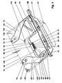
- FIG. 1 shows an exploded view of the light distribution assembly of a motor vehicle headlight in a dimetric representation.
- a lens (1) is arranged at a distance of several centimeters in front of the light exit opening (11) of the reflector (10).
- the reflector (10) and the lens (1) are interconnected by a frame, not shown, or a headlight housing.
- a cross member (30) is integrally formed or attached. At this cross member (30) is e.g. by means of the screws (77, 78) screwed to a cover carrier (40).
- the diaphragm support (40) has directly in front of the light exit opening (11) a Abblendblende (41) on which a retractable left traffic aperture (100) is mounted and guided. Under the reflector (10), a drive (130) is arranged, the actuator (136) adjusts the diaphragm support (40). The actuator (136) is mounted on the diaphragm support (40).
- the reflector (10) is, for example, an internally mirrored plastic injection-molded part with an optical axis (8). He is eg a parabolic mirror with three flats (12-14).
- the flats (12-14) are here flat surfaces, which are each arranged at least approximately parallel to the optical axis (8).
- the middle flattening (12) is at least approximately parallel to the road surface.
- the lateral flattenings (13, 14) include with the middle (12) in each case, for example, a 135 ° angle.
- the reflector (10) has around the light exit opening (11) a circumferential flange-like edge (16), which in the lower (19) and the lateral (17, 18) edge regions at least partially wider than in the other areas, cf. Figures 2 and 3.
- stop arms (21, 22) are integrally formed. These each have a U-shaped cross section, which tapers towards its free end.
- the flat underside (23) of the single stop arm (21, 22) is at least approximately parallel to the optical axis (8) and the central flattening (12).
- Below each stop arm (21, 22) is in the lateral edge region (17, 18) has a slot-shaped, downwardly open recess (25, 26), see. Figures 14 and 16.
- the single recess (25, 26) widened in the lower third of the slot depth.
- the cross member (30) has in the region of the rear outer surface of the reflector (10) is substantially in the form of a flat plate whose long edges at least partially aligned transversely to the optical axis (8) and the central flattening (12). It is arranged on the reflector (10), for example, above the optical axis (8) so that its leading edges (35, 36) penetrate the reflector outer surfaces only approximately halfway. The rest of the front edges (35, 36) overhangs.
- the length of the cross member (30) corresponds for example to 70% of the diameter of the light exit opening (11).
- the cross member (30) has on its underside two attachment points (31, 32), cf. Figures 9 and 16.
- the cross member (30) is higher in front than behind.
- the cross member (30) has in each case a threaded bore (33, 34) which are oriented normal to the attachment surfaces of the attachment points (31, 32), cf. Figure 1.
- the threads of the holes (33, 34) can also be produced by constructiverrehende thread-forming screws (77, 78).
- the cross member (30) In the middle lower region of the cross member (30) has a recess, not shown, for receiving the light source (2).
- the center line of the light source (2) lies on the optical axis (8).
- the screen carrier (40) is shown with mounted left traffic aperture (100).
- the diaphragm support (40) is, for example, a multiply bent, thin-walled sheet-metal part, which essentially surrounds a fictitious in-body (140).
- the imaginary in-body (140) has the shape of a prism whose longitudinal edges in at least one operating state of the light distribution group extend at least approximately parallel to the optical axis (8).
- the in-body (140) has a front end (141), a top (142), a bottom (143), two vertical side surfaces (145, 146) and two inclined side surfaces (147, 148).
- the bottom (143) is parallel to the top (142). Both include with the end face (141) each a 90 ° angle. Between the oblique side surfaces (147, 148) and the bottom (143) are each 135 ° angle.
- the Inelasticity (140) is mirror-symmetrically divided by a vertical center plane (9), on which, inter alia, the optical axis
- the Abblendblende (41) In front of the face (141) lies in the upper area, about the upper half, the Abblendblende (41). It covers at least largely the light exit opening (11) below the stop arms (21, 22).
- the Abblendblende (41) has an approximately centrally stepped upper edge (42), see. Figure 5, whose contour limits a right-hand traffic aperture.
- Halfway up, the anti-glare screen (41) has a horizontally disposed, outwardly formed bead (43), e.g. extends over 80% of the local aperture width.
- the lower region (44) of the dimming diaphragm (41), which extends over approximately 16% of the maximum dimming diaphragm height, is angled forwards by approximately 20 degrees. He (44) has e.g. only the length and lateral boundary which is necessary for covering the light exit opening (11) in the vicinity of the flat (12).
- Both spring supports (47, 48) are bent out of the sheet metal of the dimming diaphragm (41) around a vertical bending line. At their free end they each have a downwardly directed stop (49).
- the diaphragm carrier (40), cf. 4 goes laterally along the oblique side surfaces (147, 148) of the fictitious In stresses (140) in the grid side parts (51, 52) via.
- the apertures (56, 57) are arranged so that two support struts (53, 54) which lead towards each other at an acute angle to one another and a support strut (55) are formed.
- the support strut (55) connects the front support strut (53) respectively with the lateral edges of the Abblendblende (41).
- the grid side parts (51, 52) merge into the planar vertical side parts (61, 62). These lie against the side surfaces (145, 146) of the fictitious In stresses (140).
- the height of, for example, rectangular vertical side portions (61, 62) corresponds to e.g. 7% of the diameter of the light exit opening (11). Their length is e.g. 50% of the total length of the panel carrier (40).
- the cantilever arms (65, 66) adjoin the vertical side parts (61, 62) at a 90 ° bend. Both inwardly bent cantilevers (65, 66) lie in the unloaded state flat on the top (142) of the fictitious In stresses (140).
- the cantilevers (65, 66) run towards the vertical center plane (9). They close with the adjacent vertical side surfaces (61, 62) - in the plane of the upper side (142) - each e.g. a 30 ° angle. In the region of their free ends, the cantilevers (65, 66) are aligned parallel to the median plane (9). At the same time they run on both sides of holes (75, 76) pointed. Before each bore (75, 76) is a slot (73, 74). The straight, possibly the guide serving edges (79) of these slots (73, 74) are aligned parallel to the vertical center plane (9).
- the diaphragm support (40) is closed annularly transversely to the optical axis (8).
- the diaphragm body (40) is a dimensionally stable component, at least in the region of the dimming diaphragm (41) and the side parts (51, 52, 61, 62).
- the lattice-like construction of the side parts (51, 52) contributes to this significantly.
- the traverse (80) comprises a transverse web (81) and two tie rods (97, 98). Each tie rod (97, 98) includes at least approximately a right angle with the transverse web (81). The tie rods (97, 98) are located near the side edges of the underside (143).
- the cross bar (81) consists of a left (83) and a right arm (84). Both arms (83, 84) overlap in the middle third of the transverse strut (81).
- the arms (83, 84) are connected to each other, for example via two welding points. The welding points are each in the area of the arm ends. The end portions of the arms (83, 84) are in the overlapping zone widened towards the dimming diaphragm (41).
- the respective widening (85, 86) there is an elongate opening (87, 88) into which two narrow tabs (93, 94, 95, 96) protrude.
- the material web which delimits the respective opening (87, 88) at the front is referred to as a dome strip (91, 92).
- the widenings (85, 86), including the dome bars and the tabs (93, 94, 95, 96) of the arms (83, 84) are each bent by about 30 ° so that they enclose a 60 ° angle.
- a left traffic aperture (100) is placed, see. FIG. 4.
- FIG. 6 it consists of a stamped, multiply bent sheet metal strip which has an aperture plate (101), a stepped upper edge (102), two leaf springs (121, 122) and two actuating lugs (117, 118).
- the diaphragm plate (101) is bounded at the top by the approximately centrally stepped upper edge (102).
- the contour of this upper edge (102) allows a characteristic road illumination of a left-traffic aperture (100).
- the diaphragm plate (101) merges into two flat abutment surfaces (115, 116) which are angled forwards by 90 degrees to the front.
- On the left contact surface (115) is located on the left outside the bent down actuating tab (117).
- a comparable actuating tab (118) is also arranged on the outside of the other contact surface (116).
- two angled leaf springs (121, 122) extend in the direction of the vertical center plane (9).
- the leaf springs (121, 122) are designed kinked, the bend line at least approximately parallel to the optical axis (8).
- the lying after the bending lines end portions (123, 124) of the leaf springs (121, 122) include with the preceding areas each about 150 °.
- the bending lines of the leaf springs (121, 122) are arranged independently of the position of the left-hand traffic aperture (100) relative to the dimming diaphragm (41) such that the left-hand leaf spring (121) engages with the end region (123) and the right-hand leaf spring (122). with the area lying in front of the corresponding spring support (47, 48) contacted.
- the leaf springs (121, 122) By the leaf springs (121, 122), the left traffic diaphragm (100) is loaded, inter alia, with a force component which acts to the right - in the direction of deactivation of the left traffic aperture (100).
- the diaphragm plate (101) is delimited by a lower edge (103), which is rectilinear in the middle region. Between this lower edge (103) and the upper edge (102) are three slot-like recesses (114). The webs between the recesses (114) hide the resulting in the manufacture of the spring supports (47, 48) openings in the Abblendblende (41).
- the left-hand traffic-control panel (100) has a vertical stop (105) at the left end, to which the sloping lifting ramp (107) and a horizontal section (113) adjoin. Between the stop (105) and the lifting bevel (107) is a notch base (109). At the other end of the left traffic aperture (100) there is a stop (106) with adjacent notch (111).
- the Notch (112) lies with the notch base (109) at a height, cf. FIG. 6.
- the latching notch (111) and the horizontal section (113) are cut by the amount less deeply than the notch (112) and the notch base (109) into the diaphragm plate (101) to which the left-hand traffic control panel (100) is higher than the upper edge (42) of the diaphragm carrier (40).
- the diaphragm support (40) has between the upper portion of the Abblendblende (41) and the vertical side parts (61, 62) each have a Eckausbianung (45, 46).
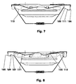
- the left-hand traffic aperture (100) used there lies on the guide at the cut edges or cut surfaces of the Eckausappelgeber (45, 46). If the left-hand traffic panel (100) is not needed, it lies in a lowered parking position, cf. et al FIG. 7. In this case, the notch base (109) and the center of the notch (112) lie on the respective bottom of the corner cutouts (45, 46).
- the left-hand traffic control panel (100) In order to move the left-hand traffic control panel (100) back into its recessed parking position, it is pressed against the actuating lug (117) from the left. In this case, the latching notch (111) of the diaphragm plate (101) jumps out of the corner recess (46). At the lifting ramps (107, 108), the diaphragm plate (101) slips behind the dimming diaphragm (41) until the notch base (109) and the Notch (112) reach the respective bottom of the corresponding Eckaus predominantlyung (45, 46). The right stop (105) limits the return stroke.
- the thickness of the panel carrier (40) and the left-hand traffic panel (100) is e.g. 0.4 mm.
- the material used for both parts for example, X 12 CrNi 177 or a similar - equipped with spring properties - material used. Non-metallic materials are also conceivable. The latter are then shaped into the necessary physical shape in another process.
- the lifting magnet (130) has a housing (131) which accommodates a winding and supports a lifting armature (136) protruding from the housing (131) and guides linearly.
- the housing (131) has on both sides each one of the lateral housing wall projecting guide web (133, 134).
- the lifting armature (136) when the winding is energized, the lifting armature (136) is pushed further out of the housing (131) by a predetermined stroke.
- the lifting armature (136) has in the region of its free end e.g. a circumferential annular groove (137).
- the drive (130) When mounting the light distribution assembly, first the drive (130) with its housing (131) arranged guide webs (133, 134) from the reflector back side between the guide rails (27, 28) of the reflector (10) and the underside of the central portion ( 12) inserted.
- the lower edge area (19) serves as the front stop.
- the housing (131) has eg at the rear of its the flattening (12) facing side a latching lug (135), with which it is locked in a corresponding recess in the reflector (10).
- the left-hand traffic aperture (100) is placed on the dimming diaphragm (41) of the diaphragm carrier (40).
- the leaf springs (121, 122) of the left traffic aperture (100) are stretched over the stops (49) under the spring supports (47, 48).
- the left-hand traffic panel (100) is located i.d.R. in the parking position.
- the finished panel support (40) is brought from below to the reflector (10) that the Abblendblende (41) in front of the light exit opening (11) comes to rest.
- With the screws (77, 78) of the diaphragm support (40) is pre-fixed without clamping force on the reflector (10).
- the transverse web (81) of the traverse (80) is pushed with the two dome strips (91, 92) of the spacers (85, 86) over the free end of the lifting armature (136) that the lifting armature (136) on both sides of two lugs (93, 95) and (94, 96) rests and the coupling bars (91, 92) for positive coupling top and bottom into the annular groove (137) resiliently engage, see. FIGS. 15 and 16.
- the cantilever arms (65, 66) are not deformed in the screw rotation direction.
- the cantilevers (65, 66) on stop edges, fixing bolts or the like can be protected against this deformation.
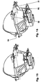
- the mounted panel support (40) is guided over its vertical side parts (61, 62) in the edge region of the reflector (10) in the lateral recesses (25, 26), cf. 15 and 16. Due to the oblique position of the cross member (30) on the reflector (10) of the diaphragm support (40) under the bias of acting as a leaf springs cantilevers (65, 66) at the edge region (17, 18) of the reflector ( 10) located stop arms (21, 22). The screen carrier (40) touches the latter via the stop sections (67, 68), cf. FIGS. 9 and 10.
- the diaphragm support (40) relative to the reflector (10) is further deflected down.
- the cantilevers (65, 66) are more bent compared to the right-hand drive setting.
- the upper edge (102) comes exactly to the level that occupies the upper edge (42) as part of a right-hand traffic.
- the contours of the upper edges (42, 102) in their respective use with respect to the vertical center plane (9) are mirror-symmetrical.
- a maximum deformation of the cantilevers (65, 66) results in the high beam setting.
- the dimming diaphragm (41) is pivoted downward by pivoting the diaphragm carrier (40), cf. FIGS. 13 and 14.
- the lifting armature (136) pushes the traverse (80) toward it - partially with bending of the tension struts (97, 98) - to the rear.
- the diaphragm support (40) pivots about a fictitious, at least approximately horizontally oriented axis, which runs essentially through the centers of the bending zones (71, 72) of the cantilever arms (65, 66).
- the Abblendblende (41) moves in front of the light exit opening in a first approximation on a circular path.
- the pivoting movement is e.g. limited by the stroke of the actuator (136).
- an elastic stop for the bending region (44) of the Abblendblende (41) may be arranged at the lower edge (19) of the reflector (10. This then results in the end of the pivoting vibration and noise damping.
- the diaphragm support (40) swings upwards under the spring action of the cantilever arms (65, 66) against the stop arms (21, 22). Since the bias of the cantilevers (65, 66) then still big enough and the game of vertical side parts (61, 62) in the recesses (25, 26) is small enough, there is no overshoot or bouncing of the diaphragm support (40). In addition, the positively coupled return stroke of the lifting armature (136) dampens the upward movement.
Landscapes
- Engineering & Computer Science (AREA)
- General Engineering & Computer Science (AREA)
- Non-Portable Lighting Devices Or Systems Thereof (AREA)
Abstract
Claims (8)
- Ensemble de distribution lumineuse à configuration de diaphragme variable pour un phare combiné feu de route-feu de croisement, en particulier pour les véhicules motorisés, avec un réflecteur (10) et une source lumineuse (2), ladite configuration de diaphragme comprenant un écran anti-éblouissant (41) et un entraînement (130) pour modifier la position dudit écran anti-éblouissant (41), caractérisé en ce que- l'écran anti-éblouissant (41) positionné devant le diaphragme de sortie de la lumière (11) du réflecteur (10) fait partie d'un support d'écran (40) placé le long du côté extérieur du réflecteur,- le support d'écran (40) possède au moins deux bras en porte-à-faux (65, 66) comme articulations qui sont réalisés en matériau élastique déformable, au moins dans certaines zones,- il existe dans la partie extérieure et postérieure du réflecteur (10) au moins un point de fixation (31, 32) pour chaque bras en porte-à-faux (65, 66),- le support d'écran (40) comprend une traverse (80) qui passe en dessous ou au-dessus du réflecteur (10) et est reliée au support (40) de manière décalée par rapport aux deux bras en porte-à-faux (65, 66)- et qu'un entraînement (130) est logé sur le côté du réflecteur (10) où se trouve la traverse (80) dont l'actionneur (136) est couplé à la traverse (80).
- Ensemble de distribution lumineuse selon la revendication 1, caractérisé en ce que le support d'écran (40) est une pièce de tôle en forme de cage à section trapézoïdale - plus étroite à la base et plus large en haut -, ladite section étant alignée de manière au moins approximativement normale par rapport à l'axe optique (8) du réflecteur (10) et symétriquement inversée par rapport au plan vertical médian (9).
- Ensemble de distribution lumineuse selon la revendication 2, caractérisé en ce que les segments du support d'écran (40) dépourvu de toute charge décrivent un corps intérieur fictif (140).
- Ensemble de distribution lumineuse selon la revendication 1, caractérisé en ce que le support d'écran (40) constitue un écran anti-éblouissant (41) en amont du diaphragme (11) du réflecteur (10), ledit écran étant orienté de manière au moins approximativement normale par rapport à l'axe optique (8) du réflecteur (10).
- Ensemble de distribution lumineuse selon la revendication 2, caractérisé en ce que des deux côtés de l'écran anti-éblouissant (41), et raccordées à celui-ci, se trouvent des pièces latérales (51, 52) qui constituent les flancs de la section trapézoïdale et sont chacune placées dans un plan normal par rapport à l'écran anti-éblouissant (41), au moins par endroits.
- Ensemble de distribution lumineuse selon la revendication 5, caractérisé en ce que les bras en porte-à-faux (65, 66) se raccordent aux zones supérieures (61, 62) des pièces latérales (51, 52) en s'infléchissant de 90°, les deux bras en porte-à-faux (65, 66) étant à l'état non-chargé dans un plan qui inclut un angle de 90° aussi bien avec le plan de l'écran anti-éblouissant (41) qu'avec le plan médian vertical (9).
- Ensemble de distribution lumineuse selon la revendication 2, caractérisé en ce que les pièces latérales (51, 52) vont en s'amenuisant vers le bas.
- Ensemble de distribution lumineuse selon la revendication 1, caractérisé en ce que la traverse (80) est constituée d'une entretoise (81) et de deux tirants (97, 98), lesdits tirants étant, à l'état non-chargé, parallèles au plan où se trouvent les bras en porte-à-faux (65, 66).
Applications Claiming Priority (3)
| Application Number | Priority Date | Filing Date | Title |
|---|---|---|---|
| DE10217785A DE10217785C1 (de) | 2002-04-21 | 2002-04-21 | Lichtverteilungsbaugruppe mit einer verstellbaren Blendenanordnung |
| DE10217785 | 2002-04-21 | ||
| PCT/DE2003/001316 WO2003089840A1 (fr) | 2002-04-21 | 2003-04-22 | Ensemble de diffusion de lumière à dispositif d'écran orientable |
Publications (2)
| Publication Number | Publication Date |
|---|---|
| EP1520135A1 EP1520135A1 (fr) | 2005-04-06 |
| EP1520135B1 true EP1520135B1 (fr) | 2007-05-23 |
Family
ID=28051323
Family Applications (1)
| Application Number | Title | Priority Date | Filing Date |
|---|---|---|---|
| EP03720281A Expired - Lifetime EP1520135B1 (fr) | 2002-04-21 | 2003-04-22 | Ensemble de diffusion de lumiere comprenant un dispositif d'ecran orientable |
Country Status (3)
| Country | Link |
|---|---|
| EP (1) | EP1520135B1 (fr) |
| DE (1) | DE10217785C1 (fr) |
| WO (1) | WO2003089840A1 (fr) |
Families Citing this family (6)
| Publication number | Priority date | Publication date | Assignee | Title |
|---|---|---|---|---|
| AT502192B1 (de) * | 2006-02-13 | 2007-02-15 | Zizala Lichtsysteme Gmbh | Blendenanordnung für eine lichteinheit |
| DE102007050206A1 (de) * | 2007-10-20 | 2009-04-23 | Hella Kgaa Hueck & Co. | Projektionsscheinwerfer für Fahrzeuge |
| DE102011121425A1 (de) | 2011-12-17 | 2013-06-20 | Volkswagen Aktiengesellschaft | Blendenanordnung für einen Fahrzeugscheinwerfer und Fahrzeugscheinwerfer mit einer solchen Blendenanordnung |
| FR2986197B1 (fr) * | 2012-01-30 | 2015-01-23 | Aml Systems | Barrette de coupure de faisceau lumineux pour module optique et le module optique |
| JP6595258B2 (ja) | 2015-08-26 | 2019-10-23 | 株式会社小糸製作所 | 灯具 |
| CN215001388U (zh) | 2021-02-09 | 2021-12-03 | 法雷奥照明湖北技术中心有限公司 | 发光组件、车灯和车辆 |
Family Cites Families (3)
| Publication number | Priority date | Publication date | Assignee | Title |
|---|---|---|---|---|
| DE19501173A1 (de) * | 1995-01-17 | 1996-07-18 | Bosch Gmbh Robert | Scheinwerfer für Fahrzeuge |
| FR2769071B1 (fr) * | 1997-09-26 | 1999-12-03 | Valeo Vision | Projecteur de type elliptique a faisceau variable, notamment pour vehicule automobile |
| FR2809801B1 (fr) * | 2000-05-31 | 2002-09-06 | Valeo Vision | Projecteur pour vehicule automobile a ecran d'occultation associe a un ressort de rappel |
-
2002
- 2002-04-21 DE DE10217785A patent/DE10217785C1/de not_active Expired - Lifetime
-
2003
- 2003-04-22 WO PCT/DE2003/001316 patent/WO2003089840A1/fr not_active Ceased
- 2003-04-22 EP EP03720281A patent/EP1520135B1/fr not_active Expired - Lifetime
Also Published As
| Publication number | Publication date |
|---|---|
| WO2003089840A1 (fr) | 2003-10-30 |
| EP1520135A1 (fr) | 2005-04-06 |
| DE10217785C1 (de) | 2003-10-16 |
Similar Documents
| Publication | Publication Date | Title |
|---|---|---|
| EP0862015B1 (fr) | Projecteur pour véhicules | |
| DE19710632A1 (de) | Scheinwerfer für Abblendlicht und Fernlicht für Fahrzeuge | |
| DE19833431C2 (de) | Kraftfahrzeugscheinwerfer für Abblendlicht und Fernlicht mit einer lageveränderbaren Lichtquelle | |
| DE102018216212B4 (de) | Fahrzeugleuchte | |
| EP0864804B1 (fr) | Système de réglage commandable à distance pour la cache d'un projecteur de véhicule | |
| EP1520135B1 (fr) | Ensemble de diffusion de lumiere comprenant un dispositif d'ecran orientable | |
| DE4407108A1 (de) | Scheinwerfer für Fahrzeuge | |
| DE19815107A1 (de) | Ausrichtungsvorrichtung für Fahrzeugleuchten | |
| AT412994B (de) | Fahrzeugscheinwerfer | |
| DE10033960B4 (de) | Kraftfahrzeugscheinwerfer mit einer Blende für mehrere Stellungen | |
| EP1201988A2 (fr) | Projecteur pour véhicule | |
| DE10044391B4 (de) | Scheinwerfer für Kraftfahrzeuge | |
| DE4243174C2 (de) | Kraftfahrzeugscheinwerfer mit einer verstellbaren Blendenanordnung | |
| DE19730413C2 (de) | Scheinwerferanordnung für Fahrzeuge mit einer Stellvorrichtung für das Abblendlicht | |
| DE102005035720A1 (de) | Leuchte mit einer langgestreckten Lichtquelle und mit einem ebenfalls langgestreckten Lichtleitelement | |
| EP1762774B1 (fr) | Projecteur | |
| EP0377866A2 (fr) | Indicateur du sens de marche d'un système d'élévateur | |
| DE69935763T2 (de) | Kraftfahrzeugscheinwerfer mit elliptischem Reflektor und mit einer schwenkbaren Blende | |
| DE60125627T2 (de) | Scheinwerfer für Kraftfahrzeug, der mehrere Lichtbündelarten erzeugen kann | |
| DE102009027849B4 (de) | Vorrichtung zum automatischen Umschalten einer Abblendblende für eine Projektionseinheit eines Scheinwerfers | |
| DE19907393A1 (de) | Scheinwerferanordnung eines Kraftfahrzeugs für Abblendlicht und Fernlicht | |
| DE10024841B4 (de) | Kraftfahrzeugscheinwerfer mit stabilisiertem Lichtbündel | |
| DE102006056333B4 (de) | Blendenanordnung für eine Lichteinheit | |
| DE2003921A1 (de) | Verstellvorrichtung fuer Kraftfahrzeugscheinwerfer | |
| EP1094428A2 (fr) | Colonne de lampes |
Legal Events
| Date | Code | Title | Description |
|---|---|---|---|
| PUAI | Public reference made under article 153(3) epc to a published international application that has entered the european phase |
Free format text: ORIGINAL CODE: 0009012 |
|
| 17P | Request for examination filed |
Effective date: 20050131 |
|
| AK | Designated contracting states |
Kind code of ref document: A1 Designated state(s): AT BE BG CH CY CZ DE DK EE ES FI FR GB GR HU IE IT LI LU MC NL PT RO SE SI SK TR |
|
| GRAP | Despatch of communication of intention to grant a patent |
Free format text: ORIGINAL CODE: EPIDOSNIGR1 |
|
| RIC1 | Information provided on ipc code assigned before grant |
Ipc: F21S 8/12 20060101ALI20061227BHEP Ipc: F21V 14/08 20060101AFI20061227BHEP |
|
| REG | Reference to a national code |
Ref country code: DE Ref legal event code: 8566 |
|
| GRAS | Grant fee paid |
Free format text: ORIGINAL CODE: EPIDOSNIGR3 |
|
| GRAA | (expected) grant |
Free format text: ORIGINAL CODE: 0009210 |
|
| AK | Designated contracting states |
Kind code of ref document: B1 Designated state(s): SE |
|
| REG | Reference to a national code |
Ref country code: SE Ref legal event code: TRGR |
|
| PLBE | No opposition filed within time limit |
Free format text: ORIGINAL CODE: 0009261 |
|
| STAA | Information on the status of an ep patent application or granted ep patent |
Free format text: STATUS: NO OPPOSITION FILED WITHIN TIME LIMIT |
|
| 26N | No opposition filed |
Effective date: 20080226 |
|
| PGFP | Annual fee paid to national office [announced via postgrant information from national office to epo] |
Ref country code: SE Payment date: 20220422 Year of fee payment: 20 |
|
| REG | Reference to a national code |
Ref country code: SE Ref legal event code: EUG |