EP1519356A2 - Procédé et dispositif pour le commande d'un panneau d'affichage à plasma - Google Patents
Procédé et dispositif pour le commande d'un panneau d'affichage à plasma Download PDFInfo
- Publication number
- EP1519356A2 EP1519356A2 EP04255898A EP04255898A EP1519356A2 EP 1519356 A2 EP1519356 A2 EP 1519356A2 EP 04255898 A EP04255898 A EP 04255898A EP 04255898 A EP04255898 A EP 04255898A EP 1519356 A2 EP1519356 A2 EP 1519356A2
- Authority
- EP
- European Patent Office
- Prior art keywords
- sustain pulse
- setting
- picture level
- period
- average picture
- Prior art date
- Legal status (The legal status is an assumption and is not a legal conclusion. Google has not performed a legal analysis and makes no representation as to the accuracy of the status listed.)
- Withdrawn
Links
Images


Classifications
-
- G—PHYSICS
- G09—EDUCATION; CRYPTOGRAPHY; DISPLAY; ADVERTISING; SEALS
- G09G—ARRANGEMENTS OR CIRCUITS FOR CONTROL OF INDICATING DEVICES USING STATIC MEANS TO PRESENT VARIABLE INFORMATION
- G09G3/00—Control arrangements or circuits, of interest only in connection with visual indicators other than cathode-ray tubes
- G09G3/20—Control arrangements or circuits, of interest only in connection with visual indicators other than cathode-ray tubes for presentation of an assembly of a number of characters, e.g. a page, by composing the assembly by combination of individual elements arranged in a matrix no fixed position being assigned to or needed to be assigned to the individual characters or partial characters
- G09G3/2007—Display of intermediate tones
- G09G3/2018—Display of intermediate tones by time modulation using two or more time intervals
- G09G3/2022—Display of intermediate tones by time modulation using two or more time intervals using sub-frames
-
- G—PHYSICS
- G09—EDUCATION; CRYPTOGRAPHY; DISPLAY; ADVERTISING; SEALS
- G09G—ARRANGEMENTS OR CIRCUITS FOR CONTROL OF INDICATING DEVICES USING STATIC MEANS TO PRESENT VARIABLE INFORMATION
- G09G3/00—Control arrangements or circuits, of interest only in connection with visual indicators other than cathode-ray tubes
- G09G3/20—Control arrangements or circuits, of interest only in connection with visual indicators other than cathode-ray tubes for presentation of an assembly of a number of characters, e.g. a page, by composing the assembly by combination of individual elements arranged in a matrix no fixed position being assigned to or needed to be assigned to the individual characters or partial characters
- G09G3/22—Control arrangements or circuits, of interest only in connection with visual indicators other than cathode-ray tubes for presentation of an assembly of a number of characters, e.g. a page, by composing the assembly by combination of individual elements arranged in a matrix no fixed position being assigned to or needed to be assigned to the individual characters or partial characters using controlled light sources
- G09G3/28—Control arrangements or circuits, of interest only in connection with visual indicators other than cathode-ray tubes for presentation of an assembly of a number of characters, e.g. a page, by composing the assembly by combination of individual elements arranged in a matrix no fixed position being assigned to or needed to be assigned to the individual characters or partial characters using controlled light sources using luminous gas-discharge panels, e.g. plasma panels
- G09G3/2803—Display of gradations
-
- G—PHYSICS
- G09—EDUCATION; CRYPTOGRAPHY; DISPLAY; ADVERTISING; SEALS
- G09G—ARRANGEMENTS OR CIRCUITS FOR CONTROL OF INDICATING DEVICES USING STATIC MEANS TO PRESENT VARIABLE INFORMATION
- G09G2320/00—Control of display operating conditions
- G09G2320/06—Adjustment of display parameters
- G09G2320/0626—Adjustment of display parameters for control of overall brightness
-
- G—PHYSICS
- G09—EDUCATION; CRYPTOGRAPHY; DISPLAY; ADVERTISING; SEALS
- G09G—ARRANGEMENTS OR CIRCUITS FOR CONTROL OF INDICATING DEVICES USING STATIC MEANS TO PRESENT VARIABLE INFORMATION
- G09G2360/00—Aspects of the architecture of display systems
- G09G2360/16—Calculation or use of calculated indices related to luminance levels in display data
-
- G—PHYSICS
- G09—EDUCATION; CRYPTOGRAPHY; DISPLAY; ADVERTISING; SEALS
- G09G—ARRANGEMENTS OR CIRCUITS FOR CONTROL OF INDICATING DEVICES USING STATIC MEANS TO PRESENT VARIABLE INFORMATION
- G09G3/00—Control arrangements or circuits, of interest only in connection with visual indicators other than cathode-ray tubes
- G09G3/20—Control arrangements or circuits, of interest only in connection with visual indicators other than cathode-ray tubes for presentation of an assembly of a number of characters, e.g. a page, by composing the assembly by combination of individual elements arranged in a matrix no fixed position being assigned to or needed to be assigned to the individual characters or partial characters
- G09G3/22—Control arrangements or circuits, of interest only in connection with visual indicators other than cathode-ray tubes for presentation of an assembly of a number of characters, e.g. a page, by composing the assembly by combination of individual elements arranged in a matrix no fixed position being assigned to or needed to be assigned to the individual characters or partial characters using controlled light sources
- G09G3/28—Control arrangements or circuits, of interest only in connection with visual indicators other than cathode-ray tubes for presentation of an assembly of a number of characters, e.g. a page, by composing the assembly by combination of individual elements arranged in a matrix no fixed position being assigned to or needed to be assigned to the individual characters or partial characters using controlled light sources using luminous gas-discharge panels, e.g. plasma panels
- G09G3/288—Control arrangements or circuits, of interest only in connection with visual indicators other than cathode-ray tubes for presentation of an assembly of a number of characters, e.g. a page, by composing the assembly by combination of individual elements arranged in a matrix no fixed position being assigned to or needed to be assigned to the individual characters or partial characters using controlled light sources using luminous gas-discharge panels, e.g. plasma panels using AC panels
- G09G3/298—Control arrangements or circuits, of interest only in connection with visual indicators other than cathode-ray tubes for presentation of an assembly of a number of characters, e.g. a page, by composing the assembly by combination of individual elements arranged in a matrix no fixed position being assigned to or needed to be assigned to the individual characters or partial characters using controlled light sources using luminous gas-discharge panels, e.g. plasma panels using AC panels using surface discharge panels
Definitions
- the present invention relates to a method for driving a plasma display panel and apparatus thereof, and more particularly, to a method for driving a plasma display panel in which a sustain driving margin can be improved and apparatus thereof.
- a plasma display panel (hereinafter, referred to as 'PDP') is a display device in which visible light is generated from phosphors when the phosphors are excited by ultraviolet rays generated upon electrical discharge in a low pressure gas.
- PDPs have advantages in that they are relatively thin and light in weight and can be made large with high definition compared to cathode ray tubes (CRTs) which have traditionally dominated the visual display market.
- a PDP consists of a number of discharge cells arranged in a matrix shape and one of the discharge cells constitutes one pixel.
- FIG. 1 is a perspective view illustrating the structure of a discharge cell of a conventional three-electrode AC surface discharge type PDP.
- the discharge cell of a conventional three-electrode AC surface discharge type PDP includes a first electrode 12Y and a second electrode 12Z both of which are formed in parallel on an upper substrate 10, and an address electrode 20X formed on a lower substrate 18.
- An upper dielectric layer 14 and a protection film 16 are stacked on the upper substrate 10 on which the first electrode 12Y and the second electrode 12Z are formed. A wall charge generated upon plasma discharge is accumulated on the upper dielectric layer 14.
- the protection film 16 serves to prevent the upper dielectric layer 14 from being damaged due to sputtering generated upon plasma discharge and also to increase emission efficiency of secondary electrons.
- the protection film 16 is formed using typically magnesium oxide (MgO) .
- a lower dielectric layer 22 and barrier ribs 24 are formed on the lower substrate 18 on which the address electrode 20X is formed.
- a phosphor layer 26 is coated on the lower dielectric layer 22 and the barrier ribs 24.
- the address electrode 20X is formed in the direction to cross the first electrode 12Y and the second electrode 12Z.
- the barrier ribs 24 are formed in parallel to the address electrode 20X and serve to prevent ultraviolet rays and a visible ray generated by a discharge from leaking toward neighboring discharge cells.
- the phosphor layer 26 is excited by ultraviolet rays generated upon plasma discharge to generate one of red, green and blue visible rays.
- An inert gas for a gas discharge is injected into discharge spaces formed between the upper substrate 10 and the barrier ribs 24 and between the lower substrate 18 and the barrier ribs 24.
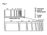
- Such a PDP is driven by dividing one frame into several sub fields having different discharge numbers in order to represent the gray level of a picture.
- Each of the sub fields is divided into a reset period for generating a discharge evenly, an address period for selecting a discharge cell, and a sustain period that represents the gray level depending on the discharge number.
- a frame period (16.67 ms) corresponding to 1/60 second is divided into eight sub fields SF1 to SF8, as shown in FIG. 2.
- each of the 8 sub fields SF1 to SF8 is divided into an address period and a sustain period.
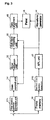
- FIG. 3 is a block diagram illustrating the structure of an apparatus for driving the conventional plasma display panel.
- the apparatus for driving the conventional PDP includes a first inverse gamma correction unit 32A, a gain control unit 34, an error diffusion unit 36, a sub field mapping unit 38 and a data alignment unit 40 all of which are connected between an input line 1 and a panel 46; and a frame memory 30, a second inverse gamma correction unit 32B, an average picture level (hereinafter, referred to as 'APL') unit 42 and a waveform generator 44 all of which are connected between the input line 1 and the panel 46.
- 'APL' average picture level
- the first and second inverse gamma correction units 32A and 32B serve to linearly convert a brightness value depending on a gray level value of a picture signal by performing inverse gamma correction for a gamma corrected video signal.
- the frame memory 30 stores data (R, G and B) for one frame and supplies the stored data to the second inverse gamma correction unit 32B.
- the APL unit 42 generates an N (N is a natural number) stage signal for controlling the number of a sustain pulse using the video data corrected by the second inverse gamma correction unit 32B.
- the gain control unit 34 functions to amplify the video data corrected in the first inverse gamma correction unit 32A as much as an effective gain.
- the error diffusion unit 36 controls the brightness value minutely by diffusing an error component of a cell to neighboring cells.
- the sub field mapping unit 38 reallocates the video data corrected in the error diffusion unit 36 by the sub field.
- the data alignment unit 40 converts the video data received from the sub field mapping unit 38 in a way that is suitable for a resolution format of the panel 46, and then supplies the converted video data to an address driving integrated circuit (hereinafter, referred to as 'IC') of the panel 46.
- 'IC' address driving integrated circuit
- the waveform generator 44 generates a timing control signal according to an N stage signal received from the APL unit 42 and provides the generated timing control signal to an address driving IC, a scan driving IC and a sustain driving IC of the panel 46.
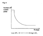
- the APL unit 42 keeps constant power consumption of the PDP and highlights a relatively bright portion when brightness of the whole picture is dark.
- the APL stage is set so that it is in inverse proportion to the number of the sustain pulse, as shown in FIG. 4. In other words, if the APL stage is high, a small number of a sustain pulse is supplied. If the APL stage is low, a large number of a sustain pulse is supplied. If the APL stage is set to be in inverse proportion to the number of a sustain pulse, power consumed in the panel is kept constant by some degree and a relatively bright portion is highlighted when brightness of the whole picture is dark.
- the APL stage is set to be in inverse proportion to the number of a sustain pulse as such, however, there is a problem that a sustain period is not utilized sufficiently since a small number of a sustain pulse is supplied in a high APL stage. That is, as the sustain pulse is supplied during some of the sustain period in the high APL stage, a sustain driving margin is lowered. Therefore, in the conventional PDP, emission efficiency when the APL stage is high is lower than those when the APL stage is not high.
- a sustain pulse As a small number of a sustain pulse is supplied in a high APL stage, the sustain pulse is supplied only during some of a sustain period that is allocated previously. Accordingly, in the high APL stage, a period where a discharge is not generated (hereinafter, referred to as 'pause period') among the sustain period widens. If the pause period widens as such, i.e., a time where the sustain pulse is supplied between a current sustain period and a next sustain period is set to be long, a sustain driving margin is lowered. For example, if the pause period widens, a sustain discharge is generated unstably because charged particles generated by a previous sustain discharge are consumed through recombination.
- the present invention seeks to address problems and disadvantages of the background art.
- a method of driving a plasma display panel including the steps of: setting the number of a sustain pulse corresponding to an average picture level (APL); and setting the period of a sustain pulse in proportion to the average picture level.
- APL average picture level
- a method of driving a plasma display panel including the steps of: setting the number of a sustain pulse corresponding to an average picture level (APL); and setting a High width of a sustain pulse in proportion to the average picture level.
- APL average picture level
- a method of driving a plasma display panel including the steps of: setting the number of a sustain pulse corresponding to an average picture level (APL); and setting a Low width of a sustain pulse in proportion to the average picture level.
- APL average picture level
- an apparatus for driving a plasma display panel including: an average brightness level unit for setting an average picture level corresponding to video data; and a period setting unit for setting the period of a sustain pulse in proportion to the average picture level set in the average brightness level unit.
- emission efficiency can be improved by supplying a sustain pulse that has a wide period as an APL stage becomes high. Furthermore, a large number of sustain pulses can be supplied in a low APL stage by setting a high minimum threshold frequency. Therefore, peak brightness of a panel can be improved. In addition, a stabilized sustain discharge can be generated by setting a maximum threshold frequency so that a constant sustain margin can be secured.
- a method for driving a plasma display panel including the steps of: setting the number of a sustain pulse corresponding to an average picture level (APL); and setting the period of a sustain pulse in proportion to the average picture level.
- APL average picture level
- the number of the sustain pulse is set in inverse proportion to the average picture level.
- the step of setting the period of the sustain pulse may include the step of setting a High width of the sustain pulse wide in proportion to the average picture level.
- the step of setting the period of the sustain pulse may include the step of setting a Low width of the sustain pulse wide in proportion to the average picture level.
- the step of setting the period of the sustain pulse may include the step of setting both a Low width and a High width of the sustain pulse wide in proportion to the average picture level.
- the greatest period of the sustain pulse may be set 0.5 ⁇ s to 10 ⁇ s higher than the smallest period of the sustain pulse.
- the period of the sustain pulse may be changed.
- the method may further include the step of setting a minimum threshold frequency over a predetermined average picture level stage so that the period of the sustain pulse is limited less than a predetermined width.
- the minimum threshold frequency may be set so that the greatest period of a sustain pulse that can be supplied widens within a range of 0.5 ⁇ s to 10 ⁇ s from the smallest period of the sustain pulse.
- the method may further include the step of setting a maximum threshold frequency below a predetermined average picture level stage so that the period of the sustain pulse is limited over a predetermined width.
- the period of the sustain pulse may increase in a step shape as the period changes from a low stage of the average picture level to a high stage of the average picture level.
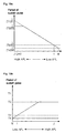
- FIG. 5a and FIG. 5b are graphs illustrating the period of a sustain pulse depending on an APL stage according to a first embodiment of the present invention.
- APL and the number of a sustain pulse have the inverse proportion relationship, as shown in FIG. 4.
- the APL stage is high, a small number of sustain pulses is supplied to a panel. If the APL stage is low, a large number of sustain pulses is provided to the panel.
- the period of a sustain pulse is set in a way that increases linearly as the APL stage becomes higher (a frequency reduces linearly), as shown in FIG. 5a and FIG. 5b. (At this time, the number of a sustain pulse actually supplied is the same as the prior art.)
- a low APL stage an i (e.g. 1024) number of a sustain pulse is supplied to the panel.
- a frequency f2 of the sustain pulse supplied in the low APL stage is set to have a high value. Accordingly, a period T2 of the sustain pulse having the inverse proportion relationship with the frequency f2 has a narrow width, for example, the period of 5 ⁇ s.
- the i Number of the sustain pulse is supplied to the panel so that it has the period of T2.
- a J (e.g. 200) number of a sustain pulse is supplied to the panel.
- a frequency f1 ⁇ f2 of the sustain pulse supplied in the high APL stage is set to have a low value. Therefore, the period T1 of the sustain pulse having the inverse proportion relationship with the frequency f1 has a wide width, for example, the period of 15 ⁇ s. That is, in the high APL stage, the J number of the sustain pulse is supplied to the panel so that it has the period of T1.
- the period of the sustain pulse increases so that it is proportional to the APL stage. If the period of the sustain pulse increases in proportion to the APL stage as such, the pause period does not widens even in the high APL stage. It is thus possible to improve the sustain driving margin.
- a period increase ratio that the period of the sustain pulse increases in proportion to the APL stage is decided experimentally.
- the period of the sustain pulse that increases in proportion to the APL stage can be set in various manners according to resolution, inch, etc. of a PDP. For instance, if a sustain pulse having the period of 5 ⁇ s is supplied in the lowest APL stage, a sustain pulse having the period of 5.5 ⁇ s to 15 ⁇ s can be provided in the highest APL stage.
- the period of the sustain pulse can increase approximately 0.5 ⁇ s to 10 ⁇ s when the lowest APL stage changes to the highest APL stage.
- the APL stage is divided into a number of section units.
- the period of the sustain pulse can be increased corresponding to the section units.
- the APL stage can be divided into a number of sections, sustain pulses having the same period can be supplied in the APL stage included in the same section, and sustain pulses having different periods can be supplied in the APL stage included in other sections.
- the higher the APL stage included in the section the greater the period of the sustain pulse is increased.
- the period of the sustain pulse can be set to be wide by increasing only the High width in the sustain pulse.
- the period of the sustain pulse can be set to be wide by increasing the High width of the sustain pulse as a low APL stage gradually changes to a high APL stage. If the High width of the sustain pulse widens as such, the sustain discharge can occur stably. In other words, if the High width of the sustain pulse widens, the time where the sustain discharge can occur becomes wide. Thus, probability that the sustain discharge can occur increases. Meanwhile, as indicated by a dotted line of FIG. 6a, the APL stage can be divided into a number of sections and the High width of the sustain pulse can increase corresponding to the sections. In other words, in the present invention, as indicated by the dotted line of FIG. 6a, the APL stage can be divided into a number of sections, sustain pulses having the same High width can be supplied in an APL stage included in the same section, and sustain pulses having different High widths can be supplied in an APL stage included in different sections.
- a Low width of the sustain pulse can be increased, as shown in FIG. 7a and FIG. 7b. That is, as shown in FIG. 7a and FIG. 7b, it is possible to set the period of the sustain pulse wide by increasing the Low width of the sustain pulse as a low APL stage gradually changes to a high APL stage. If the Low width of the sustain pulse widens in proportion to the APL stage as such, a pause period is prevented from increasing in the high APL stage and a sustain discharge is thus generated stably. In other words, if the Low width of the sustain pulse widens in proportion to the APL, the pause period where the sustain pulse is not supplied can be approximately kept constant regardless of the APL stage. If the pause period does not widen corresponding to the high APL stage as such, the sustain discharge can occur stably.
- the APL stage can be divided into a number of sections and the Low width of the sustain pulse can be increased corresponding to the sections.
- the APL stage can be divided into a number of the sections, sustain pulses having the same Low width can be supplied in an APL stage included in the same section, and sustain pulses having different Low widths can be supplied in an APL stage included in different sections.
- a method for driving a plasma display panel including the steps of: setting the number of a sustain pulse corresponding to an average picture level (APL); and setting a High width of a sustain pulse in proportion to the average picture level.
- APL average picture level
- the method step of setting the number of the sustain pulse may include setting the number of the sustain pulse in inverse proportion to the average picture level.
- a Low width of the sustain pulse may keep a predetermined width regardless of the average picture level.
- a maximum High width of the sustain pulse may be set within a range of 0.5 ⁇ s to 10 ⁇ s wider than a minimum High width of the sustain pulse.
- the step of setting the High width of the sustain pulse in proportion to the average picture level may include the steps of dividing the average picture level into a number of sections so that at least two average picture level step is included, and setting a High width of the sustain pulse using the average picture level section as a unit.
- the High width of the sustain pulse may be changed.
- the method may further include the step of setting a minimum threshold frequency over a predetermined average picture level stage so that the High width of the sustain pulse is limited less than a predetermined width.
- the minimum threshold frequency may be set so that the greatest High width of a sustain pulse that can be supplied widens within a range of 0.5 ⁇ s to 10 ⁇ s from the smallest High width of the sustain pulse.
- the method may further include the step of setting a maximum threshold frequency below a predetermined average picture level stage so that the High width of the sustain pulse is limited over a predetermined width.
- the High width of the sustain pulse may increase in a step shape as the period changes from a low stage of the average picture level to a high stage of the average picture level.
- FIG. 8a and FIG. 8b are graphs illustrating the period of a sustain pulse depending on an APL according to a second embodiment of the present invention.
- the period of the sustain pulse increases linearly (a frequency reduces linearly) as a low APL stage changes to a high APL stage.
- a minimum threshold frequency f3 i.e., a maximum sustain pulse period T3 is set. In this state, if the APL stage increases over a predetermined value, a sustain pulse having the minimum threshold frequency f3 is supplied to a panel.
- the period of the sustain pulse is set in proportion to the APL stage.
- the sustain period can be utilized sufficiently even in the APL stage by increasing the period of the sustain together pulse when the APL stage increases.
- the minimum threshold frequency f3 is set so that the period of the sustain pulse is kept constant when the APL stage exceeds a specific stage.
- the minimum limit frequency f3 is set so that the sustain pulse has the period of 15 ⁇ s
- the sustain pulse having the period of 15 ⁇ s is supplied in an APL stage of over a specific stage.
- the number of a sustain pulse is changed (the higher the APL stage, the smaller the number of the sustain pulse, as shown in FIG. 4) but the period (or frequency) of the sustain pulse keeps constant.
- the minimum threshold frequency f3 can be set in advance by a designer so that a sufficient sustain margin is secured in a high APL stage. Practically, the minimum threshold frequency f3 can be set in various ways considering resolution, inch, etc. of a PDP so that the PDP can operate stably. For instance, if a sustain pulse having the period of 5 ⁇ s is supplied in the lowest APL stage, the minimum threshold frequency f3 can be set so that the period of a sustain pulse that can be supplied by maximum becomes 5. 5 ⁇ s to 15 ⁇ s. In other words, in the second embodiment of the present invention, the threshold frequency f3 is set so that the period of the sustain pulse increases approximately 0.5 ⁇ s to 10 ⁇ s from the period of the sustain pulse supplied in the lowest APL stage.
- the period of the sustain pulse increases linearly in proportion to the APL stage, a pause period is prevented from widening in a high APL stage and a sustain driving margin can be thus improved. Furthermore, by setting the minimum threshold frequency f3 so that all the sustain pulses within a predetermined sustain period can be supplied, a stabilized sustain discharge can be generated.
- a method for driving a plasma display panel including the steps of: setting the number of a sustain pulse corresponding to an average picture level (APL); and setting a Low width of a sustain pulse in proportion to the average picture level.
- APL average picture level
- the step of setting the number of the sustain pulse may include setting the number of the sustain pulse in inverse proportion to the average picture level.
- a maximum Low width of the sustain pulse may be set within a range of 0.5 ⁇ s to 10 ⁇ s wider than a minimum Low width of the sustain pulse.
- the step of setting the Low width of the sustain pulse in proportion to the average picture level may include the steps of dividing the average picture level into a number of sections so that at least two average picture level step is included, and setting a Low width of the sustain pulse using the average picture level section as a unit.
- the Low width of the sustain pulse may be changed.
- the method may further include the step of setting a minimum threshold frequency over a predetermined average picture level stage so that the Low width of the sustain pulse is limited less than a predetermined width.
- the minimum threshold frequency may be set so that the greatest Low width of a sustain pulse that can be supplied widens within a range of 0.5 ⁇ s to 10 ⁇ s from the smallest Low width of the sustain pulse.
- the method may further include the step of setting a maximum threshold frequency below a predetermined average picture level stage so that the Low width of the sustain pulse is limited over a predetermined width.
- the High width of the sustain pulse may increase in a step shape as the period changes from a low stage of the average picture level to a high stage of the average picture level.
- an apparatus for driving a plasma display panel including: an average brightness level unit for setting an average picture level corresponding to video data; and a period setting unit for setting the period of a sustain pulse in proportion to the average picture level set in the average brightness level unit.
- the period setting unit may set a High width of the sustain pulse in proportion to the average picture level.
- the period setting unit may set a Low width of the sustain pulse in proportion to the average picture level.
- the period setting unit may set both a Low width and a High width of the sustain pulse in proportion to the average picture level.
- the apparatus may further include a limit value setting unit for setting at least one of a maximum limit value where the period of the sustain pulse can widen and a minimum limit value where the period of the sustain pulse can narrow.
- the period setting unit may control the period of the sustain pulse using at least one of the maximum limit value and the minimum limit value.
- an apparatus for driving a plasma display panel including: an average brightness level unit for setting an average picture level corresponding to video data; and a period setting unit for setting a High width of a sustain pulse in proportion to the average picture level set in the average brightness level unit.
- the apparatus may further include a limit value setting unit for setting at least one of a maximum limit value where a High width of the sustain pulse can widen and a minimum limit value where a High width of the sustain pulse can narrow.
- the period setting unit may control the High width of the sustain pulse using at least one of the maximum limit value and the minimum limit value.
- an apparatus for driving a plasma display panel including: an average brightness level unit for setting an average picture level corresponding to video data; and a period setting unit for setting a Low width of a sustain pulse in proportion to the average picture level set in the average brightness level unit.
- the apparatus may further include a limit value setting unit for setting at least one of a maximum limit value where a Low width of the sustain pulse can widen and a minimum limit value where a Low width of the sustain pulse can narrow.
- the period setting unit may control the Low width of the sustain pulse using at least one of the maximum limit value and the minimum limit value.
- FIG. 9a and FIG. 9b are graphs showing the period of a sustain pulse depending on an APL according to a third embodiment of the present invention.
- the period of the sustain pulse increases linearly (a frequency reduces linearly) as a low APL stage gradually changes to a high APL stage. Furthermore, in the third embodiment of the present invention, it is possible to arbitrarily set the number of a sustain pulse applied to a panel in a low APL stage by setting a maximum threshold frequency f4 (i.e., a minimum sustain pulse period T4).
- a maximum threshold frequency f4 i.e., a minimum sustain pulse period T4
- the number of the sustain pulse that can be supplied to the panel in the lowest APL stage can be set arbitrarily by setting the maximum threshold frequency f4 at a predetermined location of an APL stage.
- a maximum threshold frequency f4>f2 can be set so that an M (e.g. 1500) number of sustain pulses having a value greater than i (e.g. 1024) can be supplied to the panel.
- the period of the sustain pulse has a narrow period T4, for example, the period of 3 ⁇ s because it is in inverse proportion to the maximum threshold frequency. If the maximum threshold frequency f4 is set to be high and a large number of sustain pulses is thus supplied to the panel, peak brightness of the panel can be improved.
- a J (for example, 200) number of sustain pulses is supplied to the panel.
- a frequency f1 of the sustain pulse supplied in the high APL stage is set to have a low value. Accordingly, a period T1 of the sustain pulse having the inverse proportion relationship with the frequency f1 has a wide value, for example the period of 15 ⁇ s.
- a J number of a sustain pulse is supplied to the panel so that it has the period of T1.
- the third embodiment of the present invention it is possible to improve emission efficiency by linearly increasing the period of the sustain pulse in proportion to the APL stage. Furthermore, in the third embodiment of the present invention, a large number of sustain pulses is supplied in the low APL stage by setting the maximum threshold frequency f4 and peak brightness of a panel is thus increased.
- the maximum threshold frequency f4 and the minimum threshold frequency f3 can be set at the same time.
- peak brightness of the panel can be improved and a sustain discharge can be generated stably.
- the frequency i.e., period
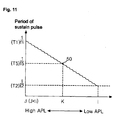
- the frequency (and the period) increases or decreases in a step shape depending on the APL stage, as shown in FIG. 11. This will be described in detail as follows. If the frequency increases or decreases linearly depending on the APL stage, it is required that a K number of a sustain pulse having the frequency of f5 (f2>f5>f1) be supplied in a predetermined step 50 of the APL.
- the frequency (or the period) of f5 can be set in a real number shape having a decimal point.
- the frequency f5 is set in a fixed number shape using a descending mode.
- the frequency is set using a descending mode.
- the frequency increases or decreases in the step shape depending on the APL stage.
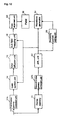
- FIG. 12 is a block diagram illustrating the structure of an apparatus for driving a plasma display panel according to an embodiment of the present invention.
- the apparatus for driving the PDP includes a first inverse gamma correction unit 52A, a gain control unit 54, an error diffusion unit 56, a sub field mapping unit 58 and a data alignment unit 60 all of which are connected between an input line 61 and a panel 66; and a frame memory 51, a second inverse gamma correction unit 52B, an APL unit 62, a frequency (period) setting unit 68 and a waveform generator 64 all of which are connected between the input line 61 and the panel 66.
- the first and second inverse gamma correction units 52A and 52B perform inverse gamma correction for a gamma-corrected video signal to linearly convert a brightness value depending on a gray level value of a picture signal.
- the frame memory 51 stores data R, G and B for one frame and supplies the stored data to the second inverse gamma correction unit 52B.
- the APL unit 62 generates an N (N is a natural number) stage signal for controlling the number of a sustain pulse using the video data corrected by the second inverse gamma correction unit 52B.
- the gain control unit 54 amplifies the video data corrected in the first inverse gamma correction unit 52A as much as an effective gain.
- the error diffusion unit 56 controls the brightness value minutely by diffusing an error component of a cell to neighboring cells.
- the sub field mapping unit 58 reallocates the video data corrected by the error diffusion unit 56 by the sub field.
- the data alignment unit 60 converts the video data received from the sub field mapping unit 58 according to a resolution format of the panel 66 and supplies the converted video data to an address driving integrated circuit (hereinafter, referred to as "IC" of the panel 66.
- IC address driving integrated circuit
- the frequency (period) setting unit 68 determines a frequency (period) of a sustain pulse depending on an APL stage supplied from the APL unit 62. For example, the frequency (period) setting unit 68 sets the period of the sustain pulse so that a sustain pulse having a wide period as the APL stage becomes high is supplied, as shown in FIG. 5a to FIG. 7b. In the above, the frequency (period) setting unit 68 widens the period of the sustain pulse by setting a High width and/or a Low width of the sustain pulse wide in proportion to the APL.
- the waveform generator 64 generates a timing control signal according to the A stage signal received from the APL unit 62. At this time, the waveform generator 64 sets the frequency of the sustain pulse according to the frequency setting signal of the sustain pulse that is received from the frequency (period) setting unit 68.
- the timing control signal generated by the waveform generator 64 is supplied to the address driving IC, the scan driving IC and the sustain driving IC of the panel 66.
- FIG. 13 is a block diagram illustrating the structure of an apparatus for driving a plasma display panel according to another embodiment of the present invention.
- the apparatus for driving the PDP includes a first inverse gamma correction unit 72A, a gain control unit 74, an error diffusion unit 76, a sub field mapping unit 78 and a data alignment unit 80 all of which are connected between an input line 81 and a panel 86; and a frame memory 71, a second inverse gamma correction unit 72B, an APL unit 72, a frequency (period) setting unit 78, a limit value setting unit 90 and a waveform generator 84 all of which are connected between the input line 81 and the panel 86.
- the first and second inverse gamma correction units 72A and 72B perform inverse gamma correction for a gamma-corrected video signal to linearly convert a brightness value depending on a gray level value of a picture signal.
- the frame memory 71 stores data R, G and B for one frame and supplies the stored data to the second inverse gamma correction unit 72B.
- the APL unit 82 generates an N (N is a natural number) stage signal for controlling the number of a sustain pulse using the video data corrected by the second inverse gamma correction unit 72B.
- the gain control unit 74 amplifies the video data corrected in the first inverse gamma correction unit 72A as much as an effective gain.
- the error diffusion unit 76 controls the brightness value minutely by diffusing an error component of a cell to neighboring cells.
- the sub field mapping unit 78 reallocates the video data corrected by the error diffusion unit 76 by the sub field.
- the data alignment unit 80 converts the video data received from the sub field mapping unit 78 according to the resolution format of the panel 86 and supplies the converted video data to an address driving IC of the panel 86.
- the limit value setting unit 90 supplies a maximum limit value and/or a minimum limit value set in the frequency (period) setting unit 88 to the frequency (period) setting unit 88.
- the frequency (period) setting unit 88 determines the frequency period of the sustain pulse corresponding to the APL stage supplied from the APL unit 82. For example, the frequency (period) setting unit 88 sets the period of the sustain pulse so that a sustain pulse having a wide period as the APL stage becomes high is supplied, as shown in FIG. 5a to FIG. 7b. In the above, the frequency (period) setting unit 88 widens the period of the sustain pulse by setting a High width and/or a Low width of the sustain pulse wide in proportion to the APL. The frequency (period) setting unit 88 sets the frequency (period) of the sustain pulse using the maximum limit value and/or the minimum limit value received from the limit value setting unit 90, as shown in FIG. 8a to FIG. 10b.
- the waveform generator 84 generates a timing control signal according to the A stage signal received from the APL unit 82. At this time, the waveform generator 84 sets the frequency of the sustain pulse according to the frequency setting signal of the sustain pulse that is received from the frequency (period) setting unit 88.
- the timing control signal generated by the waveform generator 84 is supplied to the address driving IC, the scan driving IC and the sustain driving IC of the panel 86.
- emission efficiency can be improved by supplying a sustain pulse that has a wide period as an APL stage becomes high. Furthermore, a large number of sustain pulses can be supplied in a low APL stage by setting a high minimum threshold frequency. Therefore, peak brightness of a panel can be improved. In addition, a stabilized sustain discharge can be generated by setting a maximum threshold frequency so that a constant sustain margin can be secured.
Landscapes
- Engineering & Computer Science (AREA)
- Physics & Mathematics (AREA)
- Computer Hardware Design (AREA)
- General Physics & Mathematics (AREA)
- Theoretical Computer Science (AREA)
- Plasma & Fusion (AREA)
- Control Of Indicators Other Than Cathode Ray Tubes (AREA)
- Control Of Gas Discharge Display Tubes (AREA)
Applications Claiming Priority (2)
| Application Number | Priority Date | Filing Date | Title |
|---|---|---|---|
| KR1020030067170A KR20040030316A (ko) | 2002-10-02 | 2003-09-27 | 플라즈마 디스플레이 패널의 구동방법 및 구동장치 |
| KR2003067170 | 2003-09-27 |
Publications (2)
| Publication Number | Publication Date |
|---|---|
| EP1519356A2 true EP1519356A2 (fr) | 2005-03-30 |
| EP1519356A3 EP1519356A3 (fr) | 2006-06-07 |
Family
ID=34192277
Family Applications (1)
| Application Number | Title | Priority Date | Filing Date |
|---|---|---|---|
| EP04255898A Withdrawn EP1519356A3 (fr) | 2003-09-27 | 2004-09-27 | Procédé et dispositif pour le commande d'un panneau d'affichage à plasma |
Country Status (5)
| Country | Link |
|---|---|
| US (1) | US20050078062A1 (fr) |
| EP (1) | EP1519356A3 (fr) |
| JP (1) | JP2005107536A (fr) |
| CN (1) | CN1601589A (fr) |
| TW (1) | TWI246672B (fr) |
Cited By (2)
| Publication number | Priority date | Publication date | Assignee | Title |
|---|---|---|---|---|
| EP1763001A2 (fr) * | 2005-09-08 | 2007-03-14 | Pioneer Corporation | Dispositif d'affichage à plasma |
| EP1785978A1 (fr) * | 2005-11-15 | 2007-05-16 | Samsung SDI Co., Ltd. | Dispositif d'affichage à plasma et son procédé de commande |
Families Citing this family (3)
| Publication number | Priority date | Publication date | Assignee | Title |
|---|---|---|---|---|
| KR100603242B1 (ko) * | 2005-05-31 | 2006-07-24 | 삼성전자주식회사 | 동영상 처리방법 및 장치 |
| JP5045665B2 (ja) * | 2006-02-14 | 2012-10-10 | パナソニック株式会社 | プラズマディスプレイパネルの駆動方法およびプラズマディスプレイ装置 |
| KR101471225B1 (ko) * | 2007-05-25 | 2014-12-09 | 소니 주식회사 | 표시 장치, 영상 신호 처리 방법 및 기록 매체 |
Citations (2)
| Publication number | Priority date | Publication date | Assignee | Title |
|---|---|---|---|---|
| US20010006378A1 (en) * | 1997-12-10 | 2001-07-05 | Matsushita Electric Industrial Co., Ltd. | Display apparatus capable of adjusting subfield number according to brightness |
| US20020021264A1 (en) * | 2000-03-10 | 2002-02-21 | Nec Corporation | Driving method for plasma display panels |
Family Cites Families (1)
| Publication number | Priority date | Publication date | Assignee | Title |
|---|---|---|---|---|
| JP2000322025A (ja) * | 1999-05-14 | 2000-11-24 | Nec Corp | プラズマディスプレイ装置 |
-
2004
- 2004-09-23 US US10/947,334 patent/US20050078062A1/en not_active Abandoned
- 2004-09-24 TW TW093129052A patent/TWI246672B/zh not_active IP Right Cessation
- 2004-09-27 EP EP04255898A patent/EP1519356A3/fr not_active Withdrawn
- 2004-09-27 CN CNA2004100119939A patent/CN1601589A/zh active Pending
- 2004-09-27 JP JP2004280383A patent/JP2005107536A/ja not_active Withdrawn
Patent Citations (2)
| Publication number | Priority date | Publication date | Assignee | Title |
|---|---|---|---|---|
| US20010006378A1 (en) * | 1997-12-10 | 2001-07-05 | Matsushita Electric Industrial Co., Ltd. | Display apparatus capable of adjusting subfield number according to brightness |
| US20020021264A1 (en) * | 2000-03-10 | 2002-02-21 | Nec Corporation | Driving method for plasma display panels |
Non-Patent Citations (1)
| Title |
|---|
| PATENT ABSTRACTS OF JAPAN vol. 2000, no. 14, 5 March 2001 (2001-03-05) -& JP 2000 322025 A (NEC CORP), 24 November 2000 (2000-11-24) * |
Cited By (3)
| Publication number | Priority date | Publication date | Assignee | Title |
|---|---|---|---|---|
| EP1763001A2 (fr) * | 2005-09-08 | 2007-03-14 | Pioneer Corporation | Dispositif d'affichage à plasma |
| EP1763001A3 (fr) * | 2005-09-08 | 2008-07-23 | Pioneer Corporation | Dispositif d'affichage à plasma |
| EP1785978A1 (fr) * | 2005-11-15 | 2007-05-16 | Samsung SDI Co., Ltd. | Dispositif d'affichage à plasma et son procédé de commande |
Also Published As
| Publication number | Publication date |
|---|---|
| US20050078062A1 (en) | 2005-04-14 |
| JP2005107536A (ja) | 2005-04-21 |
| CN1601589A (zh) | 2005-03-30 |
| TW200518008A (en) | 2005-06-01 |
| TWI246672B (en) | 2006-01-01 |
| EP1519356A3 (fr) | 2006-06-07 |
Similar Documents
| Publication | Publication Date | Title |
|---|---|---|
| EP1544840A2 (fr) | Dispositif et méthode pour la commande d'un panneau d'affichage à plasma | |
| EP1531451A2 (fr) | Méthode et dispositif de contrôle de l'initialisation dans un panneau d'affichage à plasma | |
| JP4299987B2 (ja) | プラズマディスプレイ装置及びその駆動方法 | |
| JP4181959B2 (ja) | プラズマディスプレイパネルの駆動方法及び駆動装置 | |
| US7408530B2 (en) | Apparatus and method of driving a plasma display panel | |
| KR100757543B1 (ko) | 플라즈마 디스플레이 패널의 구동장치 | |
| US20030179160A1 (en) | Plasma display device | |
| EP1538592A2 (fr) | Appareil et méthode de commande d'un panneau d'affichage à plasma | |
| JP4388995B2 (ja) | プラズマディスプレイパネルの駆動方法 | |
| KR100489876B1 (ko) | 플라즈마 디스플레이 패널 | |
| EP1519356A2 (fr) | Procédé et dispositif pour le commande d'un panneau d'affichage à plasma | |
| KR100563462B1 (ko) | 플라즈마 디스플레이 패널의 구동장치 및 방법 | |
| JPH1124630A (ja) | プラズマディスプレイパネルの駆動方法 | |
| KR20040030316A (ko) | 플라즈마 디스플레이 패널의 구동방법 및 구동장치 | |
| US20070024609A1 (en) | Apparatus and method of driving plasma display panel | |
| KR100733881B1 (ko) | 플라즈마 디스플레이 패널의 구동장치 및 구동방법 | |
| US7164396B2 (en) | Method and apparatus of driving plasma display panel | |
| KR100486910B1 (ko) | 플라즈마 디스플레이 패널 및 그의 구동방법 | |
| KR100489281B1 (ko) | 플라즈마 디스플레이 패널의 구동장치 및 방법 | |
| KR100692824B1 (ko) | 플라즈마 디스플레이 패널의 구동장치 및 구동방법 | |
| KR100456157B1 (ko) | 플라즈마 디스플레이 패널의 구동장치 및 방법 | |
| US20070236416A1 (en) | Method of driving plasma display panel | |
| KR20040038312A (ko) | 플라즈마 디스플레이 패널의 구동장치 및 구동방법 | |
| JP2010151859A (ja) | プラズマディスプレイ装置 |
Legal Events
| Date | Code | Title | Description |
|---|---|---|---|
| PUAI | Public reference made under article 153(3) epc to a published international application that has entered the european phase |
Free format text: ORIGINAL CODE: 0009012 |
|
| AK | Designated contracting states |
Kind code of ref document: A2 Designated state(s): AT BE BG CH CY CZ DE DK EE ES FI FR GB GR HU IE IT LI LU MC NL PL PT RO SE SI SK TR |
|
| AX | Request for extension of the european patent |
Extension state: AL HR LT LV MK |
|
| PUAL | Search report despatched |
Free format text: ORIGINAL CODE: 0009013 |
|
| AK | Designated contracting states |
Kind code of ref document: A3 Designated state(s): AT BE BG CH CY CZ DE DK EE ES FI FR GB GR HU IE IT LI LU MC NL PL PT RO SE SI SK TR |
|
| AX | Request for extension of the european patent |
Extension state: AL HR LT LV MK |
|
| 17P | Request for examination filed |
Effective date: 20060606 |
|
| 17Q | First examination report despatched |
Effective date: 20060630 |
|
| AKX | Designation fees paid |
Designated state(s): DE FR GB IT NL SE |
|
| STAA | Information on the status of an ep patent application or granted ep patent |
Free format text: STATUS: THE APPLICATION IS DEEMED TO BE WITHDRAWN |
|
| 18D | Application deemed to be withdrawn |
Effective date: 20070110 |